
Related Manuals for Aventics 580 CHARM


Summary of Contents for Aventics 580 CHARM
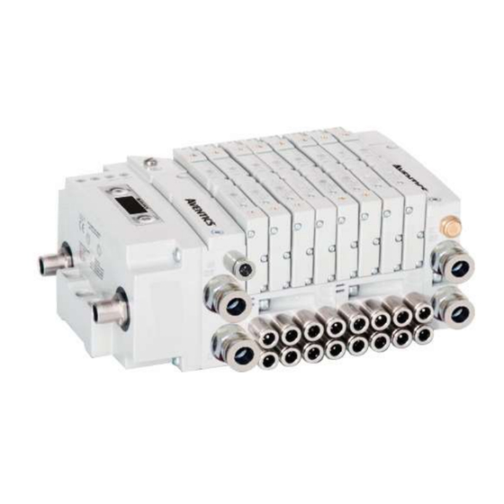
- Page 1 580 CHARM Technical Manual Distributed by Valin Corporation | www.valin.com | (800) 774-5630 | customerservice@valin.com...
- Page 2 For avoidance of doubt, AVENTICS and its affiliated companies shall have no responsibility or liability including but not limited to any and all responsibility or liability based on contract, warranty, tort, product liability for any injury or death...
- Page 3 All AVENTICS communication nodes should be grounded during the installation process. Proper grounding guidelines can be found in National Electrical code IEC 60204-1 or EN 60204-1. All AVENTICS G3 Electronics Products must only be installed or wired in accordance with ASCO AVENTICS published instructions and applicable electrical codes. ...
-
Page 4: Table Of Contents
Mapping Example for 96 Coils ......................6-40 Commissioning CHARM Node with DeltaV Software ................6-42 580 CHARM Module Changes ......................6-47 Firmware Upgrade ............................7-49 Procedure to upgrade the 580 Charm node firmware ................7-49 Appendix..............................8-52 System Specifications ........................8-52 Factory Default Settings ........................8-52 Troubleshooting .......................... -
Page 5: About Charm Overview
Now an exciting technology from Aventics extends Electronic Marshalling, and for the first time allows integrated control of pneumatic valve manifolds on one network. The Aventics 580 CHARM node, attached to an Aventics 501/502/503 Series valve manifold, can interface directly with the DeltaV Characterization Module (CHARM) I/O card from Emerson. -
Page 6: 580 Charm Introduction
The 580 CHARM Node connects to a variety of valve series including, the 501, 502, and 503. The 580 CHARM Node is capable of addressing a total of (48) coil outputs in the 501 Series and (32) coil outputs in the 502 & 503 Series, with diagnostic functionality built in. With proper assembly and termination, the 580 CHARM Node has an IP65 rating. -
Page 7: Coil Capability
In order to achieve 48 coils using the CHARM module the user will be required to use a 24 Station (48 Coil) 501 Series manifold. This manifold will utilize a special manifold block that includes another valve driver that is in addition to the driver in the 580 CHARM module. Baseplate Baseplate... -
Page 8: Maximum Coil Capability
580 CHARM Technical Manual Maximum Coil Capability If a user requires more coils than a single valve manifold can provide, multiple valve manifolds may be connected to a single CIOC when using the appropriate cable sets In order to achieve the maximum number of coils available using a single CIOC and the CHARM module the user will be required to use two valve manifolds in conjunction with each other. -
Page 9: Multiple Manifold Charm Cable Sets
580 CHARM Technical Manual Multiple manifold CHARM Cable Sets: In order to attach multiple manifolds to one CIOC, two separate cable kits must be used. CHARM Power and Communication cables: Part number: P599AF519387001 – 1.5M Length (set of 2 cables) Part number: P599AF519387002 –... -
Page 10: Pneumatic Valve Manifold
580 CHARM Technical Manual Pneumatic Valve Manifold The pneumatic valve manifold with internal circuit board technology is modular. The valve solenoid coil connections are automatically made using Z-Board ™ technology (plug together PC boards, which allow internal connections from solenoid coils to output drivers without the use of wires). This allows easy assembly and field changes. -
Page 11: Solenoid Coil Connections Using Z-Board
580 CHARM Technical Manual Solenoid Coil Connections using Z-Board Technology Z-Board ™ plug together technology connects all valve solenoids to the valve coil output drivers, located in the 580 Node. There is a maximum of 48 coil outputs available on the complete manifold assemblies. The 48 available outputs are accessed on the 501 series valves utilizing 3 or 4 station manifolds and on the 502 and 503 series utilizing 2 station manifolds. -
Page 12: Z-Board™ Connectors
580 CHARM Technical Manual Z-Board™ Connectors The 501/502/503 valve series utilize 3 different Z-Board ™ designs to achieve the single and double solenoid output functions. This yields the possible 48 single, 24 double, or various combinations of valve coil output capabilities. -
Page 13: Charm Communication Node
This module is the Communication Node to the manifold. It contains the communication electronics. It can be configured via the graphic display or via software (DeltaV). Communication Node Part Number 580 CHARM Node P580AECH2010A00 580 CHARM Node w/DIN Rail P580AECH2010DRM TD580CHTM1-12EN 06/2021 Subject to change without notice www.emerson.com 3-13 Distributed by Valin Corporation | www.valin.com | (800) 774-5630 | customerservice@valin.com... -
Page 14: Charm Node Description
580 CHARM Technical Manual CHARM Node Description Detail No. Description 5 Pin M12 Male Power & Communication (Primary) Mounting Hole 5 Pin M12 Male Power & Communication (Secondary) Module Status LED Network Status LED SET Button – used to navigate through user menus and to set parameters Graphic Display –... -
Page 15: Connector Pinouts
580 CHARM Technical Manual Connector Pinouts Industry standard M12 connectors are used for communication and power. The CHARM power & communication connector is a single keyway 5 pin male connector. CHARM Power & Communication Connector Pin-Out (Primary and Secondary). Pin No. -
Page 16: Chassis Ground
580 CHARM Technical Manual Chassis Ground All Aventics manifolds should be grounded for safety. Grounding guidelines can be found in National Electrical code IEC 60204-1 or EN 60204-1. CHASSIS GROUNDCONNECTION POINT, 501 VALVES CHASSIS GROUND CONNECTION POINT, 502 & 503 VALVES ... -
Page 17: Power Consumption
580 CHARM Technical Manual Power Consumption Power Connection Pin No. Function Description +24 VDC Valve Power +6.3 VDC Node Power Communication + Communication + Communication - Communication - Valve and Node Power Common (0 VDC) Power Rating The maximum system current capability is 4 Amps. Care should be taken not to exceed 4 Amp draw through the M12 Power connector pins. -
Page 18: Valve Power Isolator
580 CHARM Technical Manual Valve Power Isolator The Valve Power Isolator allows the user to separate the 24VDC valve power and the 6.3VDC communication power. In a typical installation there would be an isolator used on each connector of the CHARM manifold due to redundancy. - Page 19 580 CHARM Technical Manual Example layout using Valve Power Isolator DeltaV Communication Cable Network Power (6.3 VDC) 24 VDC Power Supply Valve Power (24 VDC) TD580CHTM1-12EN 06/2021 Subject to change without notice www.emerson.com 3-19 Distributed by Valin Corporation | www.valin.com | (800) 774-5630 | customerservice@valin.com...
-
Page 20: 580 Charm Node Led Functions
580 CHARM Node LED Functions Upon power up, the Module and Network Status LEDs indicate the state of the unit. There are two LEDs on the 580 CHARM Interface. The LEDs functions are described in the table below. LED Name... -
Page 21: Valve Coil Short Circuit / Open Load Protection
580 CHARM Technical Manual Valve Coil Short Circuit / Open Load Protection Output Output Type Fault Conditions Identified State No Fault Valve Solenoid Coil Driver Fault - Short Circuit, Over Temp/Over Current Fault – Open Load No Fault Valve Solenoid Coil Driver... -
Page 22: Charm Node Graphic Display
580 CHARM Technical Manual CHARM Node Graphic Display The 580 CHARM Node has an integrated graphic display that may be used to configure the parameters of the Node as well as show diagnostic information. The following graphic displays represent the main menu selections of the 580 CHARM node. Use the NEXT button to scroll through the Main menu headings shown below. -
Page 23: Bank Address Sub-Menu
580 CHARM Technical Manual Bank Address Sub-Menu 5•6•7•8 Press the SET button to enter the ADDRESS sub-menu. Press the NEXT button to scroll through the choices for the ADDRESS 5-6-7-8 Bank address/addresses of the node. SET ADDRESS Press the SET button to select the appropriate address. -
Page 24: Model Number
580 CHARM Technical Manual Model Number MODEL NUMBER The Model Number is reference only. P580AECH2010A00 Advanced Settings Menu – Flip Display ADVANCED Press the SET button to enter the ADVANCED SETTINGS SETTINGS menu. ADVANCED MENU Press the NEXT button to advance to the FLIP DISPLAY ADVANCED MENU FLIP DIPLAY screen. -
Page 25: Advanced Settings Menu - Addressing Scheme
580 CHARM Technical Manual Advanced Settings Menu – Addressing Scheme Press the SET button to enter the ADVANCED SETTINGS ADVANCED SETTINGS menu. Press the NEXT button to advance to the ADVANCED MENU ADDR. SCHEME ADVANCED MENU ADDR. SCHEME screen. Press the SET button to enter the ADDR. - Page 26 580 CHARM Technical Manual Example of Bank Order and CHARM Order mapping: CHARM Order Bank Order Reverse Standard Standard Reverse 12 Coil 14 Coil 12 Coil 14 Coil 12 End Coils 14 End Coils TD580CHTM1-12EN 06/2021 Subject to change without notice www.emerson.com...
-
Page 27: 36 Coil Optimization
580 CHARM Technical Manual 36 Coil Optimization If using address scheme “36 COIL OPT.” the manifold MUST be a certain configuration and address must be set to 6-7-8 or 2-3-4 otherwise it will not function properly. The manifold MUST be a 501 Series and use all double Z-Boards It will utilize both 3 &... -
Page 28: Pwm Control (Coils)
580 CHARM Technical Manual PWM Control (Coils) Pulse Width Modulation (PWM) is set to “DISABLED” from the factory. If this needs to be changed it can be done by referencing the menu selections below. Press the SET button to enter the... -
Page 29: Advanced Settings Menu - Parameters
580 CHARM Technical Manual Advanced Settings Menu – Parameters This menu allows the enabling / disabling of the Parameters setting. By setting the PARAMETERS LOCKED function all user settable parameters on the node will be locked out via the graphic display. -
Page 30: Factory Defaults
580 CHARM Technical Manual Factory Defaults The Factory Defaults option is there to allow the FACTORY user to return all of the parameters to how they DEFAULTS were set at the factory. Press the SET button to enter the FACTORY SET DEFAULTS DEFAULTS sub-menu. -
Page 31: Coil "Self Test" Mode
580 CHARM Technical Manual 4.10 Coil “Self Test” Mode An internal diagnostic tool can be enabled on the 580 (node) using the graphic display. This tool allows the user to confirm that all the outputs (coils), on the manifold are fully functional without needing a network connection or controller. -
Page 32: Error Messages
580 CHARM Technical Manual 4.11 Error Messages The following are automatic error messages that are displayed when specific faults occur during operation: SHORTED COIL Displayed when a short circuit condition is NO. X detected on a valve coil. OPEN COIL Displayed when an open circuit condition is NO. -
Page 33: Charm Output Configuration
580 CHARM Technical Manual CHARM Output Configuration The following chart identifies the three different output functionalities which can be selected in the properties of each CHARM output configured using DeltaV Explorer: CHARM Functionality Description Function block use Drives the output to a discrete value written by the Used with DO and Device controller and holds the output at that value. -
Page 34: Charm Configuration Options
580 CHARM Technical Manual Charm Configuration Options Depending on the output functionality chosen for each CHARM, different configuration options may be selected in DeltaV Explorer: CHARM functionality Parameter Description “Hold last value” – output is held at last value received from the controller before the failure FAIL_ACTION_MODE condition occurred. -
Page 35: Charm Mapping
The maximum number of valve solenoid coils is 96 for 501 Series and 64 for 502 & 503 Series. Output Mapping The following is a breakdown of the bit mapping associated with the Aventics 580 CHARM Valve Manifold. Solenoid coil outputs are connected to the valve coils using the Z-Boards ™... -
Page 36: Mapping Example For 36 Coils
580 CHARM Technical Manual Mapping Example for 36 Coils Assumed Settings 501 Manifold Double Z-Boards used with all valves Address set to 6-7-8 36 COIL OPT. has been Enabled CHARM Order Bank Order Reverse Standard Standard Reverse 12 Coil 14 Coil... -
Page 37: Mapping Example For 48 Coils
580 CHARM Technical Manual Mapping Example for 48 Coils Assumed Settings 501 Manifold Double Z-Boards used with all valves Address set to 5-6-7-8 CHARM Order Bank Order Reverse Standard Standard Reverse 12 Coil 14 Coil 12 Coil 14 Coil NOTE! -
Page 38: Mapping Example For 64 Coils
580 CHARM Technical Manual Manifold #1 Mapping Example for 64 Coils Assumed Settings 503 Manifolds Double Z-Boards used with all valves Address on manifold #1 set to 6-7-8 Address on manifold #2 set to 2-3-4 CHARM Order Bank Order Reverse... -
Page 39: Mapping Example For 64 Coils Cont
580 CHARM Technical Manual Manifold #2 Mapping Example for 64 Coils Cont. CHARM Order Bank Order Reverse Standard Standard Reverse 12 Coil 14 Coil 12 Coil 14 Coil RESERVED RESERVED RESERVED RESERVED RESERVED RESERVED RESERVED RESERVED NOTE! When the 12 End... -
Page 40: Mapping Example For 96 Coils
580 CHARM Technical Manual Mapping Example for 96 Coils Assumed Settings 501 Manifold Double Z-Boards used with all valves Manifold #1 Address on manifold #1 set to 5-6-7-8 Address on manifold #2 set to 1-2-3-4 CHARM Order Bank Order Reverse... - Page 41 580 CHARM Technical Manual Mapping Example for 96 Coils Cont. Manifold #2 CHARM Order Bank Order Reverse Standard Standard Reverse 12 Coil 14 Coil 12 Coil 14 Coil NOTE! When the 12 End Solenoid is energized, the 2 port is pressurized...
-
Page 42: Commissioning Charm Node With Deltav Software
This procedure assumes that the user has their DeltaV system up and running properly with standard CHARMs and all they are trying to do is add the Aventics 580 CHARM manifold. DeltaV Explorer view is set to “Details”. This shows a basic DeltaV system with four standard DO CHARMs installed. - Page 43 580 CHARM Technical Manual Right click on CHARMs and select “Auto-sense CHARMs”. Right Click Verify that all desired “DO Solenoid Valve CHARM” items are checked and click “OK”. TD580CHTM1-12EN 06/2021 Subject to change without notice www.emerson.com 6-43 Distributed by Valin Corporation | www.valin.com | (800) 774-5630 | customerservice@valin.com...
- Page 44 580 CHARM Technical Manual Highlight all DO Solenoid Valve CHARMs Right click on them and select “Assign…”. Select the desired Controller and click OK. TD580CHTM1-12EN 06/2021 Subject to change without notice www.emerson.com 6-44 Distributed by Valin Corporation | www.valin.com | (800) 774-5630 | customerservice@valin.com...
- Page 45 580 CHARM Technical Manual Right click on the CIOC that our device is connected to and select “Download > CHARMs I/O card”. Agree to confirmation window and verify download success. Right Click TD580CHTM1-12EN 06/2021 Subject to change without notice www.emerson.com 6-45 Distributed by Valin Corporation | www.valin.com | (800) 774-5630 | customerservice@valin.com...
- Page 46 Agree to confirmation window and verify download status. Right Click At this point, if there are no warning icons overlaying anything, all CHARMs that make up the Aventics 580 CHARM Node should be recognized, configured with default settings, and ready to use outputs.
-
Page 47: 580 Charm Module Changes
Right click on the 580 CHARM in DeltaV Explorer and select “Properties” to bring up to appropriate window. The “Enabled” box must be unchecked on all 580 CHARM’s and then the changes can be downloaded to the CIOC. This must be done in order for LCD menu changes to be made. - Page 48 580 CHARM Technical Manual OPTION 2: Launch the I/O Configuration in DeltaV Explorer. Select the CHARM or CHARM’s that you want to “Disable” and then right click on the selection and click the disable option. You must download the changes for them to take effect. You can select individual or a group all at once using this option.
-
Page 49: Firmware Upgrade
580 CHARM Technical Manual Firmware Upgrade Procedure to upgrade the 580 Charm node firmware Select START>DeltaV>Installation>Controller Upgrade Utility Select CHARM Components Select the CIOC to which the 580 CHARM node is connected. TD580CHTM1-12EN 06/2021 Subject to change without notice www.emerson.com 7-49 Distributed by Valin Corporation | www.valin.com | (800) 774-5630 | customerservice@valin.com... - Page 50 580 CHARM Technical Manual Select one of the integral CHARMs (there is no need to upgrade every CHARM, upgrading one will upgrade all Confirm CHARM selection TD580CHTM1-12EN 06/2021 Subject to change without notice www.emerson.com 7-50 Distributed by Valin Corporation | www.valin.com | (800) 774-5630 | customerservice@valin.com...
- Page 51 FIELD POWER 580 CHARM Technical Manual Wait for programming to complete When a power cycle is required after a firmware change has been made on the module, the LCD screen will flash a message stating that it is required.
-
Page 52: Appendix
580 CHARM Technical Manual Appendix System Specifications Electrical Valves (501, 502, 503): 24 VDC + 10%, -15% Supply Voltage Node: 6.3 VDC ± 10% Total current on the Power Connector (“Valves” and Current “Node” Pins) must not exceed 4 Amps. -
Page 53: Troubleshooting
For technical support, contact your local Aventics distributor. If further information is required, please call the Technical Support Department at (248) 596-3337. Information on device files, technical manuals, local distributors, and other ASCO, Aventics or Numatics products and support issues can be found on the Aventics web site at www.emerson.com...
Need help?
Do you have a question about the 580 CHARM and is the answer not in the manual?
Questions and answers