
Related Manuals for Aventics 580 Series


Summary of Contents for Aventics 580 Series
- Page 1 580 Series DeviceNet Technical Manual Distributed by Valin Corporation | www.valin.com | (800) 774-5630 | customerservice@valin.com...
- Page 2 Technical Manual Conditions for use of this product (1) AVENTICS Manifold ("the PRODUCT") shall be used in conditions; i) Where any problem, fault or failure occurring in the PRODUCT, if any, shall not lead to any major or serious accident.
- Page 3 All AVENTICS communication nodes should be grounded during the installation process. These grounding guidelines can be found in National Electrical code IEC 60204-1 or EN 60204-1. All AVENTICS 580 Electronics Products to be installed or wired in accordance with AVENTICS’ published instructions and applicable electrical codes. ...
-
Page 4: Table Of Contents
580 Series DeviceNet Technical Manual Table of Contents PAGE 1. About DeviceNet ............................1-5 Overview ............................1-5 580 DeviceNet Features ........................1-5 Cabling and Drop Line Lengths (as defined by DeviceNet specification) ..........1-5 2. 580 Introduction ............................2-6 Pneumatic Valve Manifold – 501 Series shown ..................2-7 Manifold Connectors........................... -
Page 5: About Devicenet
580 Series DeviceNet Technical Manual 1. About DeviceNet Overview DeviceNet is a serial communication protocol used to network industrial devices to eliminate labor intensive and expensive point to point wiring schemes. It is based on the CAN (Controller Area Network) protocol. Allen Bradley originally developed DeviceNet , but it is now supported by a multitude of manufacturers. -
Page 6: 2. 580 Introduction
IP65 rating. This manual details specific information for configuring and commissioning the AVENTICS 580 DeviceNet Node. For more information relating to pneumatic valving and valve manifold assemblies, please refer to the AVENTICS 500 Series Catalog at www.ASCO.com. Valve Side... -
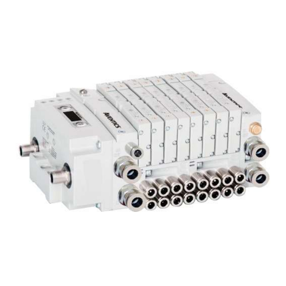
Page 7: Pneumatic Valve Manifold - 501 Series Shown
580 Series DeviceNet Technical Manual Pneumatic Valve Manifold – 501 Series shown The pneumatic valve manifold with internal circuit board technology is modular. The valve solenoid coil connections are automatically made using Z-Board ™ technology (plug together PC boards, which allow internal connections from solenoid coils to output drivers without the use of wires). -
Page 8: Manifold Connectors
580 Series DeviceNet Technical Manual Manifold Connectors Solenoid Coil Connections using Z-Board Technology for 501/502/503 valve series Z-Board ™ plug together technology connects all valve solenoids to the valve coil output drivers, located in the 580 Node. There is a maximum of 128 coil outputs available on the complete manifold assemblies. The 128 available outputs are accessed on the 501 series valves utilizing 4 station manifolds and on the 502 and 503 series utilizing 2 station manifolds. -
Page 9: Z-Board™ Connectors
580 Series DeviceNet Technical Manual Z-Board™ Connectors The 501/502/503 valve series utilize 2 different Z-Board ™ designs to achieve the single and double solenoid output functions. 501 Series 502 Series 503 Series Each series Z-Board can be selected in either SINGLE or DOUBLE output (coil) versions. -
Page 10: Communication Node
580 Series DeviceNet Technical Manual 3. Communication Node DeviceNet Node This module is the Communication Node to the manifold. It contains communication electronics and internal short circuit protection for power. It can be configured via the graphic display or via software (RSNetWorx... -
Page 11: Devicenet Tm Node Description
580 Series DeviceNet Technical Manual DeviceNet Node Description Detail No. Description 5 Pin M12 Male Communication Connector per ODVA specification Mounting Hole 4 Pin M12 Male Power Connector per ODVA specification Module Status LED Network Status LED SET Button – used to navigate through user menus and to set parameters Graphic Display –... -
Page 12: Connector Pin-Outs
580 Series DeviceNet Technical Manual Connector Pin-Outs Industry standard M12 connectors are used for communication and power. The DeviceNet communication connector is a single keyway 5 pin male connector. The Power connector is a single keyway 4 pin male connector. -
Page 13: Electrical Connections
580 Series DeviceNet Technical Manual Electrical Connections Standard Power Connector Wiring Diagram Examples Single Power Supply Example (Non-isolated commons) Male connector view Separate Power Supply Example (Non-isolated commons) Male connector view TD580DNTM1-3EN 02/22 Subject to change without notice www.AVENTICS.com Page 3-13... - Page 14 580 Series DeviceNet Technical Manual Separate Power Supply Example (Isolated commons) Male connector view Please see page 3-17 for external fuse sizing guide. When using molded connector power cables, Do Not rely on wire colors for Pin-Out. Always use pin number references.
-
Page 15: Chassis Ground
580 Series DeviceNet Technical Manual Chassis Ground All AVENTICS manifolds should be grounded for safety. Grounding guidelines can be found in National Electrical code IEC 60204-1 or EN 60204-1. CHASSIS GROUND CONNECTION POINT, 501 VALVES CHASSIS GROUND CONNECTION POINT, 502 & 503 VALVES ... -
Page 16: Power Consumption
580 Series DeviceNet Technical Manual Power Consumption Power Connection Pin No. Function Description +24 VDC (Node) Voltage used to power node electronics UNSW +24 VDC (Valve) Voltage used to power outputs (valve) SW 0 VDC Common(Node) 0 VDC (-V) Voltage used to power node electronics UNSW... -
Page 17: Recommended External Fuses
580 Series DeviceNet Technical Manual Recommended External Fuses External fuses should be chosen based upon the physical manifold configuration. Please refer to table below for the external fuse sizing chart. External Fuse Sizing Chart Power Consumption - Power Connector Pin for VALVES... -
Page 18: Diagnostics - 580 Devicenet
580 Series DeviceNet Technical Manual Diagnostics – 580 DeviceNet Node LED Functions Upon power up, the Module and Network Status LEDs indicate the state of the unit. There are two LEDs on the 580 DeviceNet Interface. The LEDs functions are described in the table below. -
Page 19: Output / Short Circuit Protection Diagnostic Status Bits
580 Series DeviceNet Technical Manual Output / Short Circuit Protection Diagnostic Status Bits Diagnostic Status Bit Action Output Status Output Type Fault Condition State No Fault Valve Solenoid Coil Driver Fault - Short Circuit, Over Temp/Over Current No Fault Valve Solenoid Coil Driver... -
Page 20: Devicenet Tm Node Graphic Display
580 Series DeviceNet Technical Manual 4. DeviceNet Node Graphic Display The 580 DeviceNet Node has an integrated graphic display that may be used to configure the parameters of the Node as well as showing diagnostic information. The following graphic displays represent the main menu selections of the 580 DeviceNet node. -
Page 21: Network Address Sub-Menu
580 Series DeviceNet Technical Manual Network Address Sub-Menu Steps to Set Address Press the SET button to enter the ADDRESS sub-menu. ADDRESS SET ADDRESS Press the NEXT button to scroll through the choices for the tens digit of the node address. -
Page 22: I/O Size
580 Series DeviceNet Technical Manual I/O Size I/O Size of Manifold I/O SIZE The I/O Size is reference only. RX=6 TX=4 TD580DNTM1-3EN 02/22 Subject to change without notice www.AVENTICS.com Page 4-22 Distributed by Valin Corporation | www.valin.com | (800) 774-5630 | customerservice@valin.com... -
Page 23: Baud Rate Sub-Menu
580 Series DeviceNet Technical Manual Baud Rate Sub-Menu Steps to Set Baud Rate BAUD RATE Press the SET button to enter the BAUD RATE sub-menu. 125K Press the NEXT button to scroll through the choices for the SET BAUD RATE... -
Page 24: Config. Mode
580 Series DeviceNet Technical Manual Config. Mode Config Mode Settings Press the SET button to enter the Config Mode sub-menu. CONFIG MODE Press the SET button to change this parameter to 32, 64, CONFIG MODE 96 or 128 ACCEPT Press the NEXT button to select Yes or No. -
Page 25: Model Number
580 Series DeviceNet Technical Manual Model Number Model Number MODEL NUMBER The Model Number is reference only. P580AEDN1010 TD580DNTM1-3EN 02/22 Subject to change without notice www.AVENTICS.com Page 4-25 Distributed by Valin Corporation | www.valin.com | (800) 774-5630 | customerservice@valin.com... -
Page 26: Advanced Settings - Fault Action / Idle Action
580 Series DeviceNet Technical Manual Advanced Settings - Fault Action / Idle Action This menu allows the enabling / disabling of the fault action parameter. The fault action parameter determines the behavior of the outputs (coils) during a communication fault. Please see page 5-35 for more details. -
Page 27: Advanced Settings - Flip Display
580 Series DeviceNet Technical Manual Advanced Settings – Flip Display Flip Display Settings ADVANCED Press the SET button to enter the ADVANCED SETTINGS SETTINGS menu. Press the NEXT button to advance to the ADVANCED ADVANCED MENU SET FAULT IDLE MENU FLIP DIPLAY screen. -
Page 28: Advanced Settings - Parameters
580 Series DeviceNet Technical Manual Advanced Settings – Parameters This menu allows the enabling / disabling of the Parameters setting. By setting the PARAMETERS LOCKED function all user settable parameters on the node will be locked out via the graphic display. -
Page 29: Factory Defaults
580 Series DeviceNet Technical Manual Factory Defaults Factory Default Settings FACTORY Press the SET button to enter the FACTORY DEFAULTS DEFAULTS sub-menu. SET DEFAULTS Press the NEXT button to select Yes or No. Selecting No will bring you back to the main FACTORY DEFAULTS menu. -
Page 30: Diagnostics
580 Series DeviceNet Technical Manual 4.10 Diagnostics DIAGNOSTICS All diagnostic information is read only Press the SET button to enter DIAGNOSTICS sub-menu. Press the NEXT button to scroll through the main diagnostic menu choices. OUTPUT INDICATION i.- Displays the coils actuated. Press NEXT to view the second word of data. -
Page 31: Diagnostics - Self Test Mode
580 Series DeviceNet Technical Manual 4.11 Diagnostics - Self Test Mode An internal diagnostic tool can be enabled on the 580 (node) using the graphic display. This tool allows the user to confirm that all of the outputs (coils), on the manifold are fully functional without needing a network connection or controller. There are two test modes that the user can choose. -
Page 32: Error Messages
580 Series DeviceNet Technical Manual 4.12 Error Messages The following are automatic error messages that are displayed when specific faults occur during operation: Displayed when a short circuit condition is SHORTED COIL NO. X detected on a valve coil. OPEN COIL Displayed when an open circuit condition is NO. -
Page 33: Configuration And Mapping
580 Series DeviceNet Technical Manual 5. DeviceNet Configuration and Mapping EDS File The EDS file contains configuration information required to establish communication to a node on a DeviceNet network. EDS files are available on the ASCO website at www.ASCO.com/G3. I/O Message Types The AVENTICS 580 DeviceNet Node supports 3 different I/O message types. -
Page 34: Explicit Messaging
580 Series DeviceNet Technical Manual Explicit Messaging Explicit messages provide multi-purpose, point-to-point communication paths between two devices. These messages use the typical request/response-oriented network communication to perform node configuration and problem diagnosis. Explicit messages typically use low priority identifiers and contain the specific meaning of the message as part of the data field;... -
Page 35: Communication Fault/Idle Mode Parameter (Sec 4.4)
580 Series DeviceNet Technical Manual Communication Fault/Idle Mode Parameter (Sec 4.4) This parameter is used to set the behaviors of output points (bits) during a communication fault or an “idle” event (when a PLC is in “Idle mode” not in RUN mode). The parameter shown below is used to determine what state/action the outputs (coils) will have during an “Idle”... -
Page 36: Devicenet Tm Mapping
The following is a breakdown of the bit mapping rules associated with the AVENTICS 580 DeviceNet Valve Manifold. Solenoid coil outputs are connected to the valve coils using the Z-Boards ™... -
Page 37: Mapping Example #1
580 Series DeviceNet Technical Manual Mapping Example #1 Assumed Settings Double Z-Boards used with all valves All Double-Solenoid valves Diagnostic Word is present (non-settable) 32 coils (4 Bytes) configuration Manifold I/O Configuration Valve Coil Number Description Bytes Diagnostic Word Local Valve Size:... -
Page 38: Mapping Example #2
580 Series DeviceNet Technical Manual Mapping Example #2 Assumed Settings Double Z-Boards used with all valves All Single-Solenoid valves Diagnostic Word is present (non-settable) 32 coils (4 Bytes) configuration Manifold I/O Configuration Description Bytes Diagnostic Word Local Valve Size: Valve Coil... -
Page 39: Diagnostic Word
580 Series DeviceNet Technical Manual Diagnostic Word Diagnostic Word Format BYTE Bit 7 Bit 6 Bit 5 Bit 4 Bit 3 Bit 2 Bit 1 Bit 0 Switched (Comm. Reserved Reserved Reserved Reserved Reserved Reserved Reserved Power Status Status) (1=Error) -
Page 40: Commissioning Devicenet
Node EDS File Download the AVENTICS 580 DeviceNet Node EDS file from www.ASCO.com/G3. Open RSNetWorx DeviceNet select “Tools” and run the “EDS Wizard” to register the AVENTICS 580 DeviceNet Node. 2) Add the 580 DeviceNet Interface to the RSNetWorx configuration... - Page 41 Double click on the DEVICENET scanner and select “Scanlist”. 4) Add the AVENTICS 580 DeviceNet node to the “Scanlist” Select Numatics 580 under available devices. Select > to move Numatics 580 into the “Scanlist”. Select Edit I/O Parameters.
- Page 42 Technical Manual I/O sizes - RX and TX Values The I/O sizes (RX and TX bytes) for the AVENTICS 580 DeviceNet node are fixed; Rx = 6 and Tx = 4. See page 4-22 for the reference location of this screen.
- Page 43 580 Series DeviceNet Technical Manual 6) Download the scanner module parameters Go online and download the scanner parameters (includes “ScanList”) to the scanner module. TD580DNTM1-3EN 02/22 Subject to change without notice www.AVENTICS.com Page 6-43 Distributed by Valin Corporation | www.valin.com | (800) 774-5630 | customerservice@valin.com...
-
Page 44: Extended Coil Capability
580 Series DeviceNet Technical Manual 7. Extended Coil Capability Extended Coil Valve driver IO Mapping IO Mapping for each additional 501 series 32 coil valve driver added to the manifold assembly Input Mapping BYTE Bit 7 Bit 6 Bit 5... -
Page 45: 501 Series, Up To 64 Solenoid Coils
580 Series DeviceNet Technical Manual 501 Series, up to 64 solenoid coils 501 series, 4 station manifold block with an integrated 32 coil valve driver To be used with 501 series valves on valve manifold assemblies with 33-64 coils. - Page 46 580 Series DeviceNet Technical Manual 501 Series, up to 128 solenoid coils 501 series, 8-station manifold with integrated 32 coil valve driver, auxiliary power connector and mid-station supply and exhaust ports To be used with 501 series valves on valve manifold assemblies with 33-128 coils.
-
Page 47: 502 And 503 Series, Up To 80 Coils
580 Series DeviceNet Technical Manual 502 and 503 Series, up to 80 coils 502 and 503 series, 4-station manifold with integrated 16 coil valve driver, power connector and mid-station supply and exhaust ports To be used with 502 and 503 series valves on valve manifold assemblies with 33-80 coils. -
Page 48: Appendix
580 Series DeviceNet Technical Manual 8. Appendix System Specifications Electrical Valves (501, 502, 503): 24 VDC + 10%, -15% Supply Voltage Node: 24 VDC ± 10% Total current on the Power Connector (“Valves” and Current “Node” Pins) must not exceed 4 Amps. -
Page 49: Troubleshooting
580 Series DeviceNet Technical Manual Troubleshooting Communication Node Symptom Possible Cause Solution Z-Board type mismatch. The wrong valve solenoid coils Check that correct Z-Board types are Single Z-Board present are being energized. installed. where double Z-Board expected or vice versa. -
Page 50: Glossary Of Terms
63 to that desired by the scanner. Please refer to Allen Bradley’s Release Notes No. 1747-5.8-RN1 for additional information. An AVENTICS term describing a user definable parameter that allows user to allocate the number of valve Assembly output drivers. - Page 51 580 Series DeviceNet Technical Manual Glossary of Terms Continued Term Description Rx = Consumed byte size; analogous to Input byte size. Rx/Tx Tx = Produced byte size; analogous to Output byte size. Method of connecting electrical circuits in which the zero (0) volt DC side is switched and the common is...
-
Page 52: Technical Support
Technical Manual Technical Support For technical support, contact your local AVENTICS distributor. If further information is required, please call AVENTICS Technical Support Department at (248) 596-3333. Issues relating to network setup, PLC programming, sequencing, software related functions, etc. should be handled with the appropriate product vendor.
Need help?
Do you have a question about the 580 Series and is the answer not in the manual?
Questions and answers