
Related Manuals for Aventics 580 PROFINET


Summary of Contents for Aventics 580 PROFINET
- Page 1 580 PROFINET Technical Manual Distributed by Valin Corporation | www.valin.com | (800) 774-5630 | customerservice@valin.com...
- Page 2 For avoidance of doubt, AVENTICS and its affiliated companies shall have no responsibility or liability including but not limited to any and all responsibility or liability based on contract, warranty, tort, product liability for any injury or death...
- Page 3 All AVENTICS communication nodes should be grounded during the installation process. Proper grounding guidelines can be found in National Electrical code IEC 60204-1 or EN 60204-1. • All AVENTICS G3 Electronics Products must only be installed or wired in accordance with ASCO AVENTICS published instructions and applicable electrical codes. •...
-
Page 4: Table Of Contents
7. PROFINET Integrated Web Server ........................41 Connecting to an Aventics 580 Profinet Node ..................41 Using the Functionality of the 580 Profinet Web Server ................42 Station Name and IP Address Configuration ....................48 User Configurable Device Parameters ....................... 49 Communication Fault/Idle Mode Parameter .................... -
Page 5: About Profinet
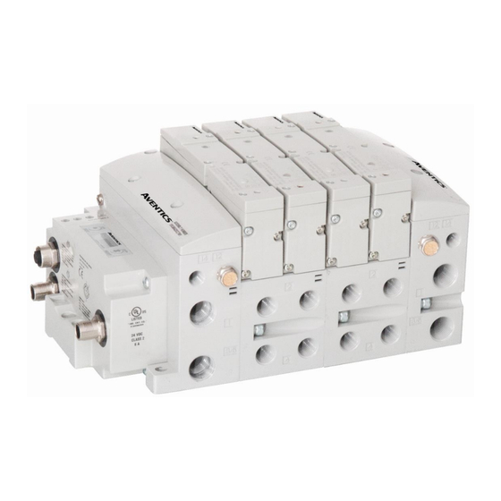
580 PROFINET Technical Manual 1. About PROFINET Overview PROFINET is an Ethernet-based networking solution for automation but has added benefits/features toward manufacturing applications. PI is the largest fieldbus organization and it is the umbrella organization responsible for both PROFIBUS and PROFINET technologies. - Page 6 Node has an IP65 rating. This manual describes specific information for configuring and commissioning the Aventics 580 PROFINET Node. For more information relating to pneumatic valving and valve manifold assemblies, please refer to the Aventics 501 and 503 Series catalogs at www.asco.com. Valve Side...
-
Page 7: Pneumatic Valve Manifold - 501 Series Shown
580 PROFINET Technical Manual Pneumatic Valve Manifold – 501 Series shown The pneumatic valve manifold with internal circuit board technology is modular. The valve solenoid coil connections are automatically made using Z-Board ™ technology (plug together PC boards, which allow internal connection from solenoid coils to output drivers without the use of wires). -
Page 8: 500 Series Manifold Stations
580 PROFINET Technical Manual 500 Series Manifold Stations Solenoid Coil Connections using Z-Board™ Technology for 50x valve series Z-Board™ plug together technology connects all valve solenoids to the valve coil output driver board, located in the valve adapter. There is a maximum of 128 coil outputs available on the complete manifold assemblies. The 128 available outputs are accessed on the 501 series valves utilizing 4 station manifolds and on the 502 and 503 series utilizing 2 station manifolds. -
Page 9: Z-Board™ Connectors
580 PROFINET Technical Manual Z-Board™ Connectors The 501/502/503 valve series utilize 2 different Z-Board ™ designs to achieve the single and double solenoid output functions. This yields the possible 32 single, 16 double, or various combinations of valve coil output capabilities. -
Page 10: Zoned Power
3. Zoned Power Zoned Power Safety and 580 Electronics alternatives Aventics 580 series electronics released as an alternative to allow immediate shipment of AVENTICS 580 series valve manifolds are not approved for Zoned power applications. These new alternative valve drivers must not to be used in Zoned Power applications. -
Page 11: 503 Series Zoned Power Application
580 PROFINET Technical Manual 503 Series Zoned Power application The Zoned Power Manifold blocks can be incorporated into a 503-manifold assembly to isolate Power to a number of valve stations, independent from the main power of the manifold. This is achieved by the integral 4 Pin M12 connector along with the modified manifold board. The total number of Zoned Power Manifold blocks is determined by the maximum solenoid outputs as defined by the type of interface (e.g. -
Page 12: 503 Series Zoned Power Example
580 PROFINET Technical Manual 503 Series Zoned Power example In the example shown below there are two Zoned Power Manifold blocks used. One is a "W" wiring option and the other is a "V" wiring option. The first (5) stations of the manifold assembly get their power from the M12 4 Pin connector at station one. -
Page 13: Communication Module
This module is the communication interface to the manifold. It contains communication electronics and internal short circuit protection for power. It can be configured via the graphic display or via software The Aventics 580 PROFINET node is tested by the PIC to ensure compatibility and interoperability. -
Page 14: 580 Node Description
580 PROFINET Technical Manual 580 Node Description Detail No. Description Link /Activity LED 5 Pin M12 Female Communication Connector per PTO specification 5 Pin M12 Female Communication Connector per PTO specification Mounting Hole 5 Pin M12 Male Power Connector Link / Activity LED... -
Page 15: Connector Pin-Outs
580 PROFINET Technical Manual Connector Pin-Outs Industry standard connectors are used for communication and power. The PROFINET communication connectors are (2) M12 D-Coded 4 pin female connectors. The Power connector is an M12 5 pin male connector. PROFINET Communication Connector Pin-Out Pin No. -
Page 16: Electrical Connections
580 PROFINET Technical Manual Electrical Connections Standard Power Connector Wiring Diagram Examples Single Power Supply Example (Non-isolated commons) Separate Power Supply Example (Isolated commons) • Please see page 19 for external fuse sizing guide. • When using molded connector power cables, Do Not rely on wire colors for Pin-Out. -
Page 17: Chassis Ground
580 PROFINET Technical Manual Chassis Ground All Aventics manifolds should be grounded for safety. Grounding guidelines can be found in National Electrical code IEC 60204-1 or EN 60204-1. CHASSIS GROUND CONNECTION POINT, 501 VALVES CHASSIS GROUND CONNECTION POINT, 502 & 503 VALVES •... -
Page 18: Power Consumption
580 PROFINET Technical Manual Power Consumption Power Connection Pin No. Function Description +24 VDC (Node) Voltage used to power node electronics UNSW 0 VDC Common (Valves) 0 VDC Voltage used to power outputs (Valves) SW 0 VDC Common (Node) 0 VDC Voltage used to power node electronics UNSW... -
Page 19: Recommended External Fuses
580 PROFINET Technical Manual Recommended External Fuses External fuses should be chosen based upon the physical manifold configuration. Please refer to table below for the fuse sizing chart. External Fuse Sizing Chart Power Consumption - Power Connector Pin for VALVES... -
Page 20: Diagnostics - 580 Profinet
Upon power up, the SF, BF, L/A and L/A LEDs indicate the state of the unit and the network connections. There are four LEDs on the 580 PROFINET node. The LEDs functions are described in the table below. LED Name... -
Page 21: Extended Coil Capability
580 PROFINET Technical Manual 5. Extended Coil Capability Below is a list of the minimum firmware level that support the Extended Coil Manifolds. Extended Solenoid Coil Capability requirements: Module Part Number Firmware Communication Module P580AEPN1010A00 Rev 2.001 Build 43054 Module firmware revision levels can be confirmed in the integrated graphic display and the built-in web browser. See pg. - Page 22 580 PROFINET Technical Manual The following example of the 580-diagnostic webpage “Node Configuration” identifies the details of a manifold configured for 64 possible coils. Number of Maximum Coils should only be adjusted if one or more additional extended coil valve driver(s) has been physically added.
- Page 23 580 PROFINET Technical Manual The following is an example of the 580-diagnostic webpage “Diagnostics” which identifies the details of the valve driver’s control of 64 possible coils TD580PNTM1-5EN 8/23 Subject to change without notice http://www.Emerson.com 5-23 Distributed by Valin Corporation | www.valin.com | (800) 774-5630 | customerservice@valin.com...
-
Page 24: 500 Series Extended Io Mapping
580 PROFINET Technical Manual 500 Series Extended IO Mapping IO Mapping for each additional 501 series 32 coil valve driver added to the manifold assembly Output Mapping BYTE Bit 7 Bit 6 Bit 5 Bit 4 Bit 3 Bit 2... -
Page 25: 501 Series, Up To 64 Solenoid Coils
580 PROFINET Technical Manual 501 Series, up to 64 solenoid coils 501 series, 4 station manifold block with an integrated 32 coil valve driver • To be used with 501 series valves on valve manifold assemblies with 33-64 coils. •... -
Page 26: 501 Series, Up To 128 Solenoid Coils
580 PROFINET Technical Manual 501 Series, up to 128 solenoid coils 501 series, 8 station manifold with integrated 32 coil valve driver, auxiliary power connector and mid-station supply and exhaust ports • To be used with 501 series valves on valve manifold assemblies with 33-128 coils. -
Page 27: 502 And 503 Series, Up To 80 Coils
580 PROFINET Technical Manual 502 and 503 Series, up to 80 coils 502 and 503 series, 4 station manifold with integrated 16 coil valve driver, power connector and mid-station supply and exhaust ports • To be used with 502 and 503 series valves on valve manifold assemblies with 33-80 coils. -
Page 28: Profinet Node Graphic Display
Technical Manual 6. Profinet Node Graphic Display The following graphic displays represent the main menu selections of the 580 PROFINET communication (node). Use the NEXT button to scroll through the Main menu headings shown below. At this level pressing the SET button allows access to the Sub-Menus. -
Page 29: Station Name
580 PROFINET Technical Manual Station Name Station Name The Station Name is addressed through the PLC. It is a STATION NAME text string that describes the function of the station in the application. IP Address Sub Menu Steps to Set IP Address Press the SET button to enter the IP ADDRESS sub-menu. -
Page 30: Subnet Mask Sub-Menu
580 PROFINET Technical Manual Subnet Mask Sub-Menu Steps to Set Subnet Mask Press the SET button to enter the Subnet Mask sub-menu. SUBNET MASK 255.255.255.0 Press the NEXT button to select the octet that you would like SUBNET MASK to change. -
Page 31: Gateway Ip
580 PROFINET Technical Manual Gateway IP Steps to Set Gateway IP Press the SET button to enter the Gateway IP sub-menu. GATEWAY IP 0.0.0.0 Press the NEXT button to select the octet that you would like GATEWAY IP to change. -
Page 32: Config. Mode
580 PROFINET Technical Manual Config. Mode Config Mode Settings Press the SET button to enter the Config Mode sub-menu. CONFIG MODE Press the SET button to change this parameter to 32, 64, CONFIG MODE 96 or 128 ACCEPT Press the NEXT button to select Yes or No. -
Page 33: Web Server Sub-Menu
580 PROFINET Technical Manual Web Server Sub-Menu This will allow the enabling/disabling of the G3 Web Server. Web-Server Steps WEB-SERVER Press the SET button to enter the Web-Server sub-menu. ENABLED Press the NEXT button to scroll through the choices to... -
Page 34: Mac Address Sub-Menu
580 PROFINET Technical Manual MAC Address Sub-Menu MAC (Machine Access Control) Address The MAC Address is a fixed unique value that cannot be MAC ADDR 0.15.24.00.06.69 edited. The actual MAC ADDR has an extra leading zero. The actual number in the example shown is 00-15-24-00-06-69... -
Page 35: Advanced Settings - Flip Display
580 PROFINET Technical Manual Advanced Settings – Flip Display Flip Display Settings Press the SET button to enter the ADVANCED ADVANCED SETTINGS menu. SETTINGS Press the NEXT button to scroll to the ADVANCED MENU ADVANCED MENU CONFIG MENU / FLIP DISPLAY. -
Page 36: Advanced Settings - Parameters
580 PROFINET Technical Manual 6.10 Advanced Settings – Parameters PARAMETER Steps Press the SET button to enter the Parameters sub-menu. PARAMETERS UNLOCKED Press the NEXT button to scroll through the choices to PARAMETERS enable or disable the feature. UNLOCKED UNLOCKED (Factory Default) -
Page 37: Factory Defaults Factory Defaults
580 PROFINET Technical Manual 6.11 Factory Defaults Factory Defaults Factory Default Settings Press the SET button to enter the FACTORY DEFAULTS FACTORY sub-menu. DEFAULTS Press the SET button to change this parameter Press the NEXT button to select Yes or No. -
Page 38: Diagnostics
580 PROFINET Technical Manual 6.12 Diagnostics All diagnostic information is read only Press the SET button to enter DIAGNOSTICS sub-menu. DIAGNOSTICS Press the NEXT button to scroll through the main diagnostic menu choices. OUTPUT INDICATION i.- Displays the coils actuated. Press NEXT to view the second word of data. - Page 39 580 PROFINET Technical Manual Diagnostics - Self Test Mode (continued) Disconnect Air and Communication from the manifold! Select the desired test mode using the graphic display. (See example below) Starting at the Home Screen, navigate the menus by selecting the NEXT button until the DIAGNOSTICS menu is shown.
-
Page 40: Error Messages
580 PROFINET Technical Manual 6.14 Error Messages The following are automatic error messages that are displayed when specific faults occur during operation: Displayed when a short circuit condition is SHORTED COIL NO. X detected on a valve coil. VALVE Displayed when +24 VDC on Pin No. 2 Valves POWER OFF (SW) and Pin No. -
Page 41: Profinet Tm
To communicate with a 580 Profinet manifold the IP address of your computer must be known. Once the IP address for the computer is known, set the IP address of the 580 Aventics manifold using one of the methods described on page 48 . -
Page 42: Using The Functionality Of The 580 Profinet
Home To get to the Aventics “Home” page, open a web browser. In the URL line, type in the IP address of the manifold and press “Enter”. The Aventics “Home” page will appear. This page shows a picture of the Aventics 580 Profinet manifold. - Page 43 580 PROFINET Technical Manual Node Configuration The “Node Configuration” page allows the user to view and modify the functional parameters of the 580 manifold. Once the changes have been made, left click on the “Update Configuration” button. The following window will appear.
- Page 44 580 PROFINET Technical Manual Node Password The “Password” popup window allows the user to set a password that disables forcing outputs or modifying parameters from the 580 Webpage. The password is blank (disabled) by default. To set the initial password, leave the “Enter Current Password”...
- Page 45 580 PROFINET Technical Manual Diagnostics The “Diagnostics” tab allows the user to monitor the 580-manifold status information. The user may also turn on valve outputs through the “580 Integrated Coils module”. Graphic of module Reports module status: = OK ✓...
- Page 46 Siemens PLC configuration. See “580 Profinet Configuration” page 51 for more information. If you do not have access to the node web server, see page 46 for commissioning of a 580 PROFINET node/manifold using Siemens TIA Portal Software. Quick Start Manual The Quick Start Manual tab accesses the embedded Quick Start Manual in the node.
- Page 47 The “Download GSDML” tab provides links to download the embedded GSDML file stored in the node or to connect with the Aventics website. Aventics.com The “Aventics.com” tab is a quick link to Aventics’ website. The computer must have internet access for this tab to be functional. TD580PNTM1-5EN...
-
Page 48: Station Name And Ip Address Configuration
580 PROFINET Technical Manual Station Name and IP Address Configuration The IP address of the Aventics 580 Profinet node may be configured via several different methods: • Step 7 software configuration • Graphical display Integrated Web Page Configuration Tab Station name, IP address, Subnet Mask and Gateway address parameter selections can all be configured from this page. -
Page 49: User Configurable Device Parameters
580 PROFINET Technical Manual User Configurable Device Parameters The Aventics 580 PROFINET node allows the user to set many user options which define how the manifold behaves in certain instances. The following are descriptions of these device parameters. Settable Via... -
Page 50: Communication Fault/Idle Mode Parameter
580 PROFINET Technical Manual Communication Fault/Idle Mode Parameter This parameter is used to describe characteristics or behaviors of output points. The parameter shown below is used to determine what state the outputs of a particular G3 output module will have during an “Idle” event or a “Fault”... -
Page 51: Gsdml File
GSDML File The GSDML file contains configuration information required to establish communication to a node on a PROFINET network. The GSDML file is available on the Aventics website at https://fieldbus.asco.com/. 580 Profinet PLC Configuration Follow your Siemens software help guide to install the 580 PROFINET GSDML file (Latest GSDML files are available at https://fieldbus.asco.com/). - Page 52 580 PROFINET Technical Manual From the “Hardware catalog” other field devices expand; PROFINET IO\Valves\Numatics\580. Then double click 580 The 580 is added to the “Devices and networks” configuration TD580PNTM1-5EN 8/23 Subject to change without notice http://www.Emerson.com 7-52 Distributed by Valin Corporation | www.valin.com | (800) 774-5630 | customerservice@valin.com...
- Page 53 580 PROFINET Technical Manual Select the Profinet port of the PLC then drag a line to Profinet port of the 580. The 580 Manifold is connected and assigned to PLC_1. Double click the 580 Manifold to begin I/O configuration. TD580PNTM1-5EN...
- Page 54 580 PROFINET Technical Manual The 580 Manifold is expanded to show the I/O map. Select from the hardware catalog (right tab) and select “32- COILS”. Then save the configuration and download to the PLC TD580PNTM1-5EN 8/23 Subject to change without notice http://www.Emerson.com...
-
Page 55: 580 Profinet Tm Station Name
580 Profinet Station Name The Aventics 580 manifold requires a station name that associates it to the Siemens Profinet PLC configuration. When the PLC recognizes the 580’s “Station Name” as a match to a configured station in the PLC’s Profinet... -
Page 56: Profinet Tm
The bit mapping for a 580 PROFINET manifold remains similar, the only variation depends on whether a single of a double solenoid valve is used. The following is a breakdown of the bit mapping rules associated with the Aventics 580 Valve Manifold. -
Page 57: Mapping Example No. 1
580 PROFINET Technical Manual Mapping Example No. 1 Assumed Settings All double solenoid valves Double Z-Boards , stations 1-8 32 coils (4 Bytes) allocated (non-settable) Manifold I/O Configuration Description Bytes Local Valve Size: Total: Valve Coil Number How to Order... -
Page 58: Mapping Example No. 2
580 PROFINET Technical Manual Mapping Example No. 2 Assumed Settings All single solenoid valves Double Z-Boards , stations 1-8 32 coils (4 Bytes) allocated (non-settable) Manifold I/O Configuration Description Bytes Local Valve Size: Total: Valve Coil Number How to Order... -
Page 59: 10. Appendix
580 PROFINET Technical Manual 10. Appendix 10.1 System Specifications ELECTRICAL Valves (501, 502 and 503): 24 VDC + 10%, -15% Supply Voltage Node: 24 VDC ± 10% Total current on the Auxiliary Power Connector (“Valves” and “Node” Pins) must not Current exceed 4 Amps. -
Page 60: Troubleshooting
580 PROFINET Technical Manual 10.3 Troubleshooting Communication Node Symptom Possible Cause Solution Z-Board type mismatch. The wrong valve solenoid coils Check that correct Z-Board types are Single Z-Board present are being energized. installed. See page 56 for bit mapping where double Z-Board rules. - Page 61 Technical Manual Technical Support For technical support, contact your local Aventics distributor. If further information is required, please call Aventics Technical Support Department at (248) 596-3337. Issues relating to network setup, PLC programming, sequencing, software related functions, etc. should be handled with the appropriate product vendor.
Need help?
Do you have a question about the 580 PROFINET and is the answer not in the manual?
Questions and answers