
Related Manuals for Aventics 580 PROFIBUS DP


Summary of Contents for Aventics 580 PROFIBUS DP
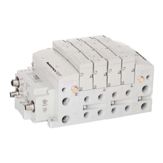
- Page 1 580 PROFIBUS Technical Manual Distributed by Valin Corporation | www.valin.com | (800) 774-5630 | customerservice@valin.com...
- Page 2 For avoidance of doubt, AVENTICS and its affiliated companies shall have no responsibility or liability including but not limited to any and all responsibility or liability based on contract, warranty, tort, product liability for any injury or death...
- Page 3 All AVENTICS communication nodes should be grounded during the installation process. Proper grounding guidelines can be found in National Electrical code IEC 60204-1 or EN 60204-1. All AVENTICS 580 Electronics Products must only be installed or wired in accordance with ASCO AVENTICS published instructions and applicable electrical codes. ...
-
Page 4: Table Of Contents
580 PROFIBUS DP Technical Manual Table of Contents PAGE About PROFIBUS DP ..........................1-5 Overview ............................1-5 580 PROFIBUS DP Node Features ...................... 1-5 Cabling and Drop Line Lengths (as defined by PROFIBUS specification) ..........1-5 580 PROFIBUS DP Introduction ........................2-6 Pneumatic Valve Manifold –... -
Page 5: About Profibus Tm Dp
580 PROFIBUS DP Technical Manual 1. About PROFIBUS Overview PROFIBUS DP is a communication protocol used to network industrial devices to eliminate labor intensive and expensive point to point wiring schemes. Siemens originally developed PROFIBUS DP, but it is now supported by a multitude of manufacturers and the protocol standard governed by the PROFIBUS Trade Organization (PTO). -
Page 6: 580 Profibus Tm Dp Introduction
This manual details specific information for configuring and commissioning the Aventics 580 PROFIBUS DP Node. For more information relating to pneumatic valving and valve manifold assemblies, please refer to the Aventics 501, 502 and 503 Series catalogs at www.asco.com. Valve Side... -
Page 7: Pneumatic Valve Manifold - 501 Series Shown
580 PROFIBUS DP Technical Manual Pneumatic Valve Manifold – 501 Series shown The pneumatic valve manifold with internal circuit board technology is modular. The valve solenoid coil connections are automatically made using Z-Board ™ technology (plug together PC boards, which allow internal connection from solenoid coils to output drivers without the use of wires). -
Page 8: Manifold Connectors
580 PROFIBUS DP Technical Manual Manifold Connectors Solenoid Coil Connections using Z-Board Technology for 501/502/503 valve series Z-Board ™ plug together technology connects all valve solenoids to the valve coil output drivers, located in the 580 Node. There is a maximum of 128 coil outputs available on the complete manifold assemblies. The 128 available outputs are accessed on the 501 series valves utilizing 3 and 4 station manifolds and on the 502 and 503 series utilizing 2 station manifolds. -
Page 9: Z-Board™ Connectors
580 PROFIBUS DP Technical Manual Z-Board™ Connectors The 501/502/503 valve series utilize 2 different Z-Board ™ designs to achieve the single and double solenoid output functions. This yields the possible 32 single, 16 double, or various combinations of valve coil output capabilities. -
Page 10: Zoned Power
580 PROFIBUS DP Technical Manual 3. Zoned Power 503 Series Zoned Power application The Zoned Power Manifold blocks can be incorporated into a 503 manifold assembly to isolate Power to a number of valve stations, independent from the main power of the manifold. -
Page 11: 503 Series Zoned Power Example
580 PROFIBUS DP Technical Manual 503 Series Zoned Power example In the example shown below there are two Zoned Power Manifold blocks used. One is a "W" wiring option and the other is a "V" wiring option. The first (5) stations of the manifold assembly get their power from the M12 4 Pin connector at station one. -
Page 12: Communication Module
This module is the communication interface to the manifold. It contains communication electronics and internal short circuit protection for power. It can be configured via the graphic display or via software (Class 2 Master required). The Aventics 580 PROFIBUS DP node is tested by the Profibus Interface Center to ensure compatibility and interoperability. -
Page 13: 580 Profibus Tm Dp Node
580 PROFIBUS DP Technical Manual 580 Node Description Detail No. Description 5 Pin M12 Male Communication Connector per PTO specification 5 Pin M12 Female Communication Connector per PTO specification Mounting Hole 5 Pin M12 Male Power Connector Module Status LED Network Status LED SET Button –... -
Page 14: Connector Pin-Outs
580 PROFIBUS DP Technical Manual Connector Pin-Outs Industry standard connectors are used for communication and power. The PROFIBUS DP communication connectors are a M12 reverse key 5 pin male connector and a M12 reverse key 5 pin female connector. The Power connector is an M12 5 pin male connector. -
Page 15: Electrical Connections
580 PROFIBUS DP Technical Manual Electrical Connections Standard Power Connector Wiring Diagram Examples Single Power Supply Example (Non-isolated commons) Separate Power Supply Example (Isolated commons) Please see page 4-18 for external fuse sizing guide. When using molded connector power cables, Do Not rely on wire colors for Pin-Out. -
Page 16: Chassis Ground
580 PROFIBUS DP Technical Manual Chassis Ground All Aventics manifolds should be grounded for safety. Grounding guidelines can be found in National Electrical code IEC 60204-1 or EN 60204-1. CHASSIS GROUND CONNECTION POINT, 501 VALVES CHASSIS GROUND CONNECTION POINT, 502 & 503 VALVES ... -
Page 17: Power Consumption
580 PROFIBUS DP Technical Manual Power Consumption Power Connection Pin No. Function Description +24 VDC (Node) Voltage used to power node electronics UNSW 0 VDC Common (Valves) 0 VDC Voltage used to power outputs (Valves) SW 0 VDC Common (Node) 0 VDC Voltage used to power node electronics UNSW +24 VDC (Valves) Voltage used to outputs (Valves) SW... -
Page 18: Recommended External Fuses
580 PROFIBUS DP Technical Manual Recommended External Fuses External fuses should be chosen based upon the physical manifold configuration. Please refer to table below for the fuse sizing chart. External Fuse Sizing Chart Power Consumption - Power Connector Pin for VALVES Description Current Number of Solenoid Valve Coils Energized Simultaneously... -
Page 19: Diagnostics - 580 Profibus
580 PROFIBUS DP Technical Manual Diagnostics – 580 PROFIBUS DP Node LED Functions Upon power up, the Module and Network Status LEDs indicate the state of the unit. There are two LEDs on the 580 PROFIBUS DP node. The LEDs functions are described in the table below. LED Name Color Status... -
Page 20: Extended Coil Capability
580 PROFIBUS DP Technical Manual 5. Extended Coil Capability The Extended Coil manifolds must be connected to a 580 Electronics Node to operate. Not all 580 supported protocols will support the Extended Coil Manifolds. Below is a list of the hardware and minimum firmware levels that support the Extended Coil Manifolds. -
Page 21: Extended Coil Valve Driver Io Mapping
580 PROFIBUS DP Technical Manual Extended Coil Valve driver IO Mapping IO Mapping for each additional 501 series 32 coil valve driver added to the manifold assembly Input Mapping BYTE Bit 7 Bit 6 Bit 5 Bit 4 Bit 3 Bit 2 Bit 1 Bit 0... -
Page 22: 501 Series, Up To 64 Solenoid Coils
580 PROFIBUS DP Technical Manual 501 Series, up to 64 solenoid coils 501 series, 4 station manifold block with an integrated 32 coil valve driver To be used with 501 series valves on valve manifold assemblies with 33-64 coils. ... -
Page 23: 501 Series, Up To 128 Solenoid Coils
580 PROFIBUS DP Technical Manual 501 Series, up to 128 solenoid coils 501 series, 8 station manifold with integrated 32 coil valve driver, auxiliary power connector and mid-station supply and exhaust ports To be used with 501 series valves on valve manifold assemblies with 33-128 coils. ... -
Page 24: 502 And 503 Series, Up To 80 Coils
580 PROFIBUS DP Technical Manual 502 and 503 Series, up to 80 coils 502 and 503 series, 4 station manifold with integrated 16 coil valve driver, power connector and mid-station supply and exhaust ports To be used with 502 and 503 series valves on valve manifold assemblies with 33-80 coils. ... - Page 25 580 PROFIBUS DP Technical Manual 6. 580 PROFIBUS DP Node Graphic Display The following graphic displays represent the main menu selections of the 580 PROFIBUS DP communication (node). Use the NEXT button to scroll through the Main menu headings shown below. At this level pressing the SET button allows access to the Sub-Menus.
-
Page 26: Network Address Sub-Menu
580 PROFIBUS DP Technical Manual Network Address Sub-Menu Steps to Set Address Press the SET button to enter the ADDRESS sub-menu. ADDRESS Press the NEXT button to scroll through the choices for the SET ADDRESS hundreds digit of the node address. Press the SET button to select the hundreds digit and move into the tens digit selection. -
Page 27: Set Slave Address Lock Sub-Menu
580 PROFIBUS DP Technical Manual Set Slave Address Lock Sub-Menu Steps to Set SSA LOCK Press the SET button to enter the SSA Lock sub-menu. SSA LOCK DISABLED Press the NEXT button to enable / disable the SSA Lock SSA LOCK DISABLED ENABLE- allows the address to be set only through the 580 graphic display... -
Page 28: 500 Series Extended Coil Capability
580 PROFIBUS DP Technical Manual 500 Series Extended Coil Capability Steps to Set Coil Configuration CONFIG MODE Press the SET button to enter the CONFIG MODE sub-menu. STANDARD Press the SET button and the NEXT button to change the number SELECT COILS 32=STANDARD of coils. -
Page 29: Advanced Settings - Flip Display
580 PROFIBUS DP Technical Manual Model Number Model Number MODEL NUMBER The Model Number is reference only. P580AEPT1010 Advanced Settings – Flip Display Flip Display Settings Press the SET button to enter the ADVANCED SETTINGS menu. ADVANCED SETTINGS Press the NEXT button to scroll to the ADVANCED MENU /FLIP ADVANCED MENU FLIP DISPLAY DISPLAY. -
Page 30: Advanced Settings - Parameters
580 PROFIBUS DP Technical Manual Advanced Settings - Parameters Parameter Steps ADVANCED Press the SET button to enter the Parameters sub-menu. SETTINGS Press the NEXT button to scroll to the ADVANCED MENU / ADVANCED MENU FLIP DISPLAY PARAMETERS. ADVANCED MENU Press the SET button to enter the PARAMETERS sub menu. -
Page 31: Factory Defaults
580 PROFIBUS DP Technical Manual Factory Defaults Factory Default Settings Press the SET button to enter the FACTORY DEFAULTS sub- FACTORY DEFAULTS menu. SET DEFAULTS Press the NEXT button to select Yes or No. Selecting No will bring you back to the main FACTORY DEFAULTS menu. -
Page 32: Diagnostics
580 PROFIBUS DP Technical Manual Diagnostics All diagnostic information is read only DIAGNOSTICS Press the SET button to enter DIAGNOSTICS sub-menu. Press the NEXT button to scroll through the main diagnostic menu choices. OUTPUT INDICATION -Displays the coils actuated. Press NEXT to view SET SELF TEST the second word of data. -
Page 33: Diagnostics - Self Test Mode
580 PROFIBUS DP Technical Manual 6.10 Diagnostics - Self Test Mode An internal diagnostic tool can be enabled on the 580 (node) using the graphic display. This tool allows the user to confirm that all of the outputs (coils), on the manifold are fully functional without needing a network connection or controller. There are two test modes that the user can choose. -
Page 34: Error Messages
580 PROFIBUS DP Technical Manual 6.11 Error Messages The following are automatic error messages that are displayed when specific faults occur during operation: Displayed when a short circuit condition is SHORTED COIL NO. X detected on a valve coil OPEN COIL Displayed when an open circuit condition is NO. -
Page 35: Profibus Tm Dp Configuration And Mapping
GSD File The GSD file contains configuration information required to establish communication to a node on a PROFIBUS DP network. The GSD file is available on the Aventics website at www.asco.com/g3. User Configurable Device Parameters The Aventics 580 PROFIBUS DP node allows the user to set many user options which define how the manifold behaves in certain instances. -
Page 36: Fail Safe Mode Parameter
580 PROFIBUS DP Technical Manual Fail Safe Mode Parameter This parameter is used to set the behaviors of coil output points (bits) during a communication fault. The parameter shown below is used to determine what state the outputs will have during a “Fault” event. It will allow control of all valves on the manifold. -
Page 37: Commissioning 580 Profibus
580 PROFIBUS DP Technical Manual Commissioning 580 Profibus with Siemens TIA Portal Software Follow your Siemens software help guide to install the 580 PROFIBUS DP GSD file (Latest GSD files are available at www.asco.com/g3). Once the GSD file is installed select the various components to assemble your 580 node and manifold configuration and I/O map. - Page 38 580 PROFIBUS DP Technical Manual From the “Hardware catalog” other field devices expand; Profibus DP\Valves\Numatics Inc.\580. Then double click 580 The Slave_1 580 node and manifold is added to the “Devices and networks” configuration TD580PTTM1-2EN 07/2020 Subject to change without notice www.asco.com 7-38 Distributed by Valin Corporation | www.valin.com | (800) 774-5630 | customerservice@valin.com...
- Page 39 580 PROFIBUS DP Technical Manual Select the Profibus port of the PLC then drag a line to Profibus port of the Slave_1 580 node and manifold. The Slave_1 580 node and manifold is connected and assigned to PLC_1. Double click the Slave_1 580 node and manifold to begin I/O configuration.
- Page 40 580 PROFIBUS DP Technical Manual The Slave_1 580 node and manifold is expanded to show the I/O map. Select “1-32 Coils” from the hardware catalog (right tab) to match the required I/O configuration. Once the I/O configuration is chosen, it is then downloaded to the PLC. TD580PTTM1-2EN 07/2020 Subject to change without notice...
-
Page 41: Profibus Tm
DP manifold remains similar, the only variation depends on whether a single of a double solenoid valve is used. The following is a breakdown of the bit mapping rules associated with the Aventics 580 Valve Manifold. Solenoid coil outputs are connected to the valve coils using the Z-Boards ™... -
Page 42: Mapping Example No.1
580 PROFIBUS DP Technical Manual Mapping Example No.1 Assumed Settings Double Z-Boards , stations 1-8 32 coils (4 Bytes) allocated Manifold I/O Configuration Description Bytes Local Valve Size: Total: Valve Coil How to Order (Bit Number) Part Number 8501AV8H100VA00 R501A2B40MA00F1 H501AMM4BMA0010 R501A2B40MA00F1 H501AMM4BMA0010... -
Page 43: Mapping Example No.2
580 PROFIBUS DP Technical Manual Mapping Example No.2 Assumed Settings All single solenoid valves Double Z-Boards , stations 1-8 32 coils (4 Bytes) allocated Manifold I/O Configuration Description Bytes Local Valve Size: Total: Valve Coil How to Order (Bit Number) Part Number 8501AV8H100VA00 R501A2B10MA00F1... -
Page 44: Appendix
580 PROFIBUS DP Technical Manual 9. Appendix System Specifications ELECTRICAL Valves (501, 502, 503): 24 VDC ± 10% Supply Voltage Node: 24 VDC ± 10% Total current on the Power Connector (“Valves” and “Node” Pins) must not exceed 4 Current Amps. -
Page 45: Glossary Of Terms
Issues relating to network setup, PLC programming, sequencing, software related functions, etc. should be handled with the appropriate product vendor. Information on device files, technical manuals, local distributors, and other Aventics or Numatics products and support issues can be found on the Aventics web site at www.asco.com...
Need help?
Do you have a question about the 580 PROFIBUS DP and is the answer not in the manual?
Questions and answers