Table of Contents
Advertisement
Quick Links
Advertisement
Table of Contents
Troubleshooting

Related Manuals for Huvitz CDR-3100


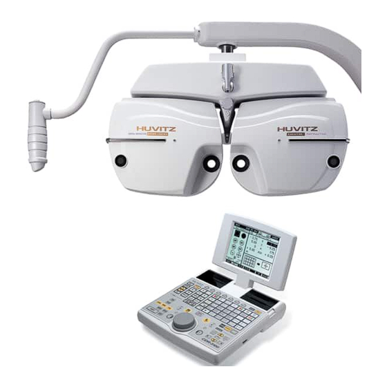
Summary of Contents for Huvitz CDR-3100
-
Page 1: Contents
CDR-3100 Service Manual HUVITZ Co., Ltd - 1 -... -
Page 2: Table Of Contents
4 Troubleshooting........................24 4.1 Troubleshooting problems attributed to the power supply ......... 24 4.1.1 Wiring diagram of the CDR-3100 Junction Box ......... 24 4.1.2 No reaction on its start-up of the Refractor Body ........24 4.1.2 All the disks are hardly rotating with abnormal noise during initialization... - Page 3 4.2 Troubleshooting problems in initializing disks positions........26 4.2.1 PI sensors information on the main board..........26 4.2.1 Any of the disks is slightly off-position and comes in the same position every time after its initialization................26 4.2.2 A disk stops at a random position after the initialization ......26 4.2.3 A disk rotates more than 10 cycles during the initialization .....
-
Page 4: Introduction
In case the instrument cannot be repaired by the procedures described in this manual, contact HUVITZ with product and problem status information like serial number of the product, version number of the Operating System, details of the symptom, and etc. -
Page 5: Simplified Qc Check Procedure
2. Simplified QC Check Procedure 2.1 Purpose of the 2 QC check The purpose of this 2 inspection is to find out any possible changes or unwanted defects caused during its shipping and unshipping by improper handling of the product. This 2 procedure aids to check original alignment and settings of each product and to give first-aid measures. -
Page 6: Post Aging Test Procedures For The Refractor Body
[Key sequence] ALT + MENU ALT + START ALT + TEST 2.2.2 Post aging test procedures for the Refractor Body ① Check the PD adjustment function • Press PD button. • Check if the PD-check lenses are inserted properly. • Turn the dial clockwise or counter-clockwise several times. •... - Page 7 Operation Panel. • Finish this step when all the auxiliary lenses are checked. Press the ESC button. ⑤ Check the direction of rotary prism lenses • Reset the Refractor Body. Press the CLEAR button twice. • Select rotary prism lenses. Press the BIBO or BDBU button.
-
Page 8: Recommended System Configuration For Qc Check
2.3 Recommended system configuration for QC check 2.3.1 Configuration for Aging Test (*) The Operation Panel used for this configuration should be a QCs version. (*) Refractor Bodies can be connected together for the QC check as many as the total length of daisy-chained connection is less than about 500m. -
Page 9: Disassembling Procedures And Parts Description
3. Disassembling Procedures And Parts Description 3.1 Removing the main body cover 3.1.1 Removing the Rear cover of the main body Unscrew the screws and remove the Rear Cover Ass’y R (or Front cover Ass’y L). M3 Screw M3 Screw Rear Cover Ass’y Fig. -
Page 10: Removing The Front Cover Of The Main Body
3.1.2 Removing the Front cover of the main body Unscrew the screws and remove the Front cover Ass’y R (or Front cover Ass’y L) M3 Screw M3 Screw M3 Screw Front Cover Ass’y Fig. 3-1-2 -10-... -
Page 11: Description Of Parts
3.2 Description of parts 3.2.1 Main body (#1) PARTS NAME DISK1 ASS’Y DISK2 ASS’Y DISK3 ASS’Y DISK4 ASS’Y DISK5 ASS’Y DISK6 ASS’Y SPH-GEAR ASS’Y VD-MIRROR ASS’Y I-GEAR ASS’Y - 11 -... -
Page 12: Main Body (#2)
3.2.2 Main body (#2) PARTS NAME DIsK1 SENSOR ASS’Y DIsK3 SENSOR ASS’Y AUX-GEAR2 SENSOR ASS’Y AUX-GEAR1 SENSOR ASS’Y DIsK2 SENSOR ASS’Y DIsK4 SENSOR ASS’Y REF-PLATE ASS’Y2 REF-PLATE ASS’Y1 DIsK5 SENSOR ASS’Y -12-... -
Page 13: Main Body (#3)
3.2.3 Main body (#3) PARTS NAME DISK2 MOTOR DISK1 MOTOR DISK5 MOTOR DISK4 MOTOR DISK3 MOTOR AUX-GEAR3 MOTOR DISK6 MOTOR AUX-GEAR1 MOTOR AUX-GEAR2 MOTOR DISK6 SENSOR ASS’Y AUX GEAR3 - 13 -... -
Page 14: Auxiliary Gar Ass'y
3.2.4 Auxiliary gar ass’y PARTS NAME AUX-GEAR1 I-GEAR SPACER2 I-GEAR SPACER1 I-AXIS HOLDER I-GEAR AXIS I-GEAR SPACER AUX-GEAR2 -14-... -
Page 15: Sph Gear Ass'y
3.2.5 SPH gear ass’y PARTS NAME SPH SHAFT TOP SPACE WASHER DISK1 GEAR SPH-SHAFT SPH-SHAFT BASE DISK2 GEAR - 15 -... -
Page 16: Ref-Plate Ass'y
3.2.6 REF-PLATE ass’y REF-PLATE ASS’Y1 REF-PLATE ASS’Y2 PARTS NAME REF-PLATE HOLDER1 REF-PLATE HOLDER2 REF-PLATE SHAFT REF-PLATE -16-... -
Page 17: Replacement Procedure For Pi Sensor
3.3 Replacement procedure for PI sensor (1) Remove the covers of the main body, front and rear. (2) Disconnect the connector of the sensor to be replaced. (3) Unscrew the screws and remove the sensor. (*) With a cutter knife, draw lines along the shape of the sensor board on the metal frame as shown in the figure 3-3 so that you can replace and fix a... -
Page 18: Removing The Covers Of The Upper Part Of The Main Body
3.4 Removing the covers of the upper part of the main body -18-... -
Page 19: Limit Switches And Motors In The Upper Part Of The Main Body
3.5 Limit switches and motors in the upper part of the main body PD limit switch Tilting motor Tilting limit switch PD control motor - 19 -... -
Page 20: Disassembling The Can Boards In The Main Body
3.6 Disassembling the CAN boards in the main body Remove this knob first CAN BOARDS -20-... -
Page 21: Disassembling The Converter Box
3.7 Disassembling the Converter Box Pull this way to open 4pin port External power inlet - 21 -... -
Page 22: Disassembling The Junction Box
3.8 Disassembling the Junction Box Access hole to voltage- setting switch Junction Box SMPS Power inlet & Fuse holder 4-pin CAN ports 6-pin CAN port 8-pin CAN & power port for the Main Body -22-... -
Page 23: Lens Cleaning
3.9 Lens Cleaning 3.9.1 Cleaning lens in the main body (1) Turn off the instrument. (2) Remove the covers of the main body. (3) Turn on the instrument. (4) Execute the lens-cleaning mode in the Operation Panel by pressing the buttons like the key sequence in below (operation panel of QCs version supports lens-cleaning process by allowing the operator position the lenses at the position of test window one by one and disk by disk.) -
Page 24: Troubleshooting
4 Troubleshooting 4.1 Troubleshooting problems attributed to the power supply 4.1.1 Wiring diagram of the CDR-3100 Junction Box 4.1.2 No reaction on its start-up of the Refractor Body If turning on the power leads to no reaction in the Refractor Body, it may be attributed to the fault of the power supply, especially the 5V for all digital circuitries. -
Page 25: All The Disks Are Hardly Rotating With Abnormal Noise During Initialization
red), GND and DC 7V(brown), GND and DC 18V(gray)). If any of the measuring resistance shows short circuit, try to check either the 8- pin cable or the Refractor Body itself is short-circuited by disconnecting the 8-pin cable from both the Refractor and the Junction Box and measuring the resistance in all combinations of two pins in it. -
Page 26: Troubleshooting Problems In Initializing Disks Positions
4.2 Troubleshooting problems in initializing disks positions 4.2.1 PI sensors information on the main board No. of No. of No. of No. of Connector Connector Connector Connector Motor No. Motor No. Function Function (Left) (Left) (Right) (Right) Motor/PI Motor/PI Motor/PI Motor/PI Rotates Spherical Disk 1(0.25 D Step) Rotates Spherical Disk 1(0.25 D Step) -
Page 27: A Disk Rotates More Than 10 Cycles During The Initialization
(*) After replacing the limit switch ass’y, it is required to check and calibrate the initial position of the Refractor PD(default is 64mm) or the convergence(default is flat). Contact the technical support division at Huvitz for detailed information about it. -
Page 28: Problem In Communication
4.3 Problem in communication 4.3.1 Basic things in CAN (Controller Area Network) Refractor Body Sub line CANH Terminator Terminator Main line CANL ① CAN use only 2 lines (wires). ② The length of main line can reach upto 100m. ③ The length of sub lines’ is limited to 3m. ④... -
Page 29: All The Devices On The Can Do Not Respond
to case 3. belong 2. If there is only one terminator in multi-system, error rate of communication could increase. 4.3.3 All the devices on the CAN do not respond - Terminator is absent or Cable is shorted or CAN B/D is out of order. ①... - Page 30 - Voltage difference between the ground and either of the CANH and CANL should be 2.5±0.5 V. . Keep the instrument turned on and disconnect the 2-pin communication cable. . Contact the ‘-‘ probe to the ground pin(printed ‘C3’ on the PCB) in the 6-pin connector.
-
Page 31: Appendix
Huvitz Co., Ltd. Outside the factory of Huvitz, in the absence of special tools, it is not allowed to perform any calibration procedure upon any other part of the instrument other than the disk position explained herein. - Page 32 - Refractor selection keys ‘R’ for the right ‘L’ for the left - Disk, or the motor, number selection keys ‘+’ or ‘-‘ - Changing disk position keys Dial (turn it clockwise or counter clockwise) - Saving changes and exiting the calibration mode ALT + SET (*) There is no way to cancel the result of calibration and abort the calibration mode.
-
Page 33: Wiring Diagram And Board Description
B. Wiring diagram and board description 1. Junction box CONVERTER CONVERTER OPERATION PHOROPTOR TERMINATOR BOX1 BOX2 PANEL HEAD FUSE1 FUSE2 FUSE3 (5V) (7.2V) (24V) AC IN SMPS - 33 -... -
Page 34: Motor Board - Left Side
2. Motor board – left side LIMIT RS232 & CAN MOTOR BOARD LEFT EEPROM MOTOR(J15~J24) J15~J24 JTAG-ICE POWER MOTOR -34-... -
Page 35: Motor Board - Right Side
3. Motor board – right side LIMIT PHOTO SENSOR(J15~J23) PD LED SWITCH RS232 & CAN MOTOR BOARD RIGHT EEPROM MOTOR(J3~J9, J11,J12,J14) J3~J9,J11,J12,J14 JTAG-ICE POWER MOTOR 4. CAN board (interior type) CANH CANL COMMUNICATION PORT(CANH, CANL) CAN BOARD(INTERIOR) CANH CANL POWER &... -
Page 36: Can Board (Exterior Type)
5. CAN board (exterior type) CANH CANL COMMUNICATION PORT(CANH, CANL) CAN BOARD(EXTERIOR) CANH CANL POWER & RS232 DC 9V POWER THE END. -36-...
Need help?
Do you have a question about the CDR-3100 and is the answer not in the manual?
Questions and answers
The operation console has a blank screen with NO info on it at all. The screen HV is working as the back-light can be seen working but no info. The head unit goes threw it's power-up and all seems to work just still nothing on the operations screen.Also battery is new.
A blank operation console screen on the Huvitz CDR-3100, despite the backlight functioning, could indicate a fault in the power supply, particularly the 5V supply required for all digital circuitries. It is recommended to check whether the power supply is properly connected to the wall outlet.
This answer is automatically generated