Table of Contents
Advertisement
Advertisement
Table of Contents

Related Manuals for Huvitz CRK-7000


Summary of Contents for Huvitz CRK-7000
- Page 1 Auto-Ref/Keratometer CRK-7000 Service Manual Auto Ref/Keratometer CRK-7000...
-
Page 2: Table Of Contents
3. Electrical System ....................19 4. Principles of Measurement ..................26 V. Repair Standard ......................29 1. Replacing expendables ................... 29 2. Checking and control ....................31 3. CRK-7000 Total ass’y .................... 48 VI. Troubleshooting ......................66 VII. Technical Materials ....................... 73... -
Page 3: Important Notice
The information in this publication has been carefully checked and is believed to be entirely accurate at the time of publication. SHANGHAI HUVITZ assumes no responsibility, however, for possible errors or omissions, or for any consequences resulting from the use of the information contained herein. - Page 4 The information in this publication has been carefully checked and is believed to be entirely accurate at the time of publication. SHANGHAI HUVITZ assumes no responsibility, however, for possible errors or omissions, or for any consequences resulting form the use of the information contained herein.
-
Page 5: Introduction
II. Introduction 1. Outline of the instrument Auto Ref/Keratometer CRK-7000 is the equipment to provide the information of Spherical, Cylindrical and Axis while measuring the refraction of examinee’s eyes. Auto Ref/Keratometer CRK-7000 is the equipment that can measure the corneal curvature of examinee. -
Page 6: Safety Information
III. Safety Information 1. Introduction Safety is everyone’s responsibility. The safe use of this equipment is largely dependent upon the installer, user, operator, and maintainer. It is imperative that personnel study and become familiar with this entire manual before attempting to install use, clean, service or adjust this equipment and any associated accessories. -
Page 7: Safety Symbols
Auto-Ref/Keratometer CRK-7000 2. Safety Symbols The International Electrotechnical Commission (IEC) has established a set of symbols for medical electronic equipment which classify a connection or warn of any potential hazards. The classifications and symbols are shown below. Save these instructions I and O on power switch represent ON and OFF respectively. -
Page 8: Environment Factors
3. Environment Factors Please avoid the environment below for the operation and storage of the equipment. Where the equipment is exposed to water vapor. Don’t operate an equipment with a wet hand. Where the equipment is exposed to direct sunlight. Where the temperature changes extremely. - Page 9 Auto-Ref/Keratometer CRK-7000 Don’t plug the AC power cord into the outlet before the connection between devices equipment completed. This can generate the defect. Pull out the power cord with holding the plug, not the cord. For the normal operation of the machine, please keep the ambient temperature is 10℃...
-
Page 10: Safety Precautions
(5) Customer maintenance of this equipment may only be performed as stated in the User’s Manual and Service Manual. Any additional maintenance may only be performed by SHANGHAI HUVITZ’s service technicians or other authorized persons. (6) The manufacturer is only responsible for effects on safety, reliability,... - Page 11 SHANGHAI HUVITZ’s. If the customer makes use of other accessories, use them only if there are usability under technical safety aspects has been proved and confirmed by SHANGHAI HUVITZ or the manufacturer of the accessory. (9) Only persons who have undergone proper training and instructions are authorized to install, use, operate, and maintain this equipment.
- Page 12 (14) Before every operation, proceed with visual inspection on the equipment exterior to seek any mechanical damage(s) to ensure the proper functioning. (15) Do not obstruct any ventilation outlet for proper heat dissipation. (16) In case of any presence of smoke, spark or abnormal noise/smell from the machine, please power off immediately and pull out the plug.
-
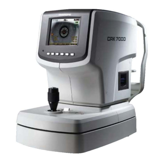
Page 13: Product Outline
Auto-Ref/Keratometer CRK-7000 IV. Product Outline 1. Nomenclature [Figure 1. Front] Height Adjustment Mark: Adjusts the eyes’ height of examinees Operation Buttons: Selecting of functions Operation Lamp : Indicates whether or not the electric power is on ٍ Display Monitor: Monitor for measurement Measurement Button: Performing the measurement by pressing it after focusing. - Page 14 [Figure 2. Back Section] Forehead Rest: Preventing the vibration by fixing the forehead Measuring Object Lens: Measuring the image imaging on the retina of eyes. Chin Rest: Preventing the vibration by fixing the chin Power Switch: Switch for power on/off Chin-rest Adjusting Lever: Adjusting the up and down position of Chin-rest.
- Page 15 Auto-Ref/Keratometer CRK-7000 [Figure 3. Bottom Section] Power Supply Socket: A socket connecting to exterior power plug Serial Interface Connector: A terminal connecting to the exterior equipment Clamping Bolt: Fixing the system stage NOTE As connecting to exterior monitor, noises can appear on the monitor owing...
-
Page 16: Optical System
2. Optical System 2-1. Overview... - Page 17 Auto-Ref/Keratometer CRK-7000 2-2. List of Optical Components 1 : patient’s eye 2-1, -2 : LED for lightening cornea 3-1, -2, -3 : ring unit of the keratometry 4-1 : protective glass 4-2 : half mirror 4-3 : half mirror 4-4 : reflection mirror...
- Page 18 2-3. Light Paths of the System A: External illumination (2-1, 2-2 B: Corneal observation system C: Ker measurement system (3-1, -2, -3 D: Projection system of the REF measurement chart E: Projection system of the REF measurement F: Projection system of the target chart...
-
Page 19: Electrical System
Auto-Ref/Keratometer CRK-7000 3. Electrical System 3-1. Electrical construction diagram [Figure 5.]... - Page 20 3-2. Power input electrical block diagram DC Output +5V, 4A +5V, 2A +12V, 1.8A Power AC 100- Dual SMPS switch 240~ Line (DPST) Fuse [Figure 6.]...
- Page 21 Auto-Ref/Keratometer CRK-7000 3-3 Electrical wiring 3-3-1. Main Board CN16 CN15 +3.3V MAIN BOARD CN17 CN13 +12V CN18 CN19 CN14 +12V +5V, +12V CN12 CN10 CN9 CN8 CN23 CN11 +5V, +12V [Figure 7.] 3-3-2. Description of wire harness connection of main B/D Connecto No.
- Page 22 CN 13 Not used Not connect CN 14 Not used Not connect Chart LED B/D CON1 CN 15 REF LED/LAMP LED REF PI B/D J2 REF LED B/D J1 CN 16 REF Motor connector REF Motor assy CN 17 KER CMOS camera connector KER Cmos B/D J2 CN 18 REF CCD camera connector...
- Page 23 Auto-Ref/Keratometer CRK-7000 3-3-3. Base IO Interface Board CON12 CON3 CON9 +5V, 2A CON10 CON17 +12V, 1.8A CON1 CON13 CON4 +12V CON2 CON14 CON16 CON6 CON15 CON11 +5V, 4A +5V, 2A +12V, 1.8A BASE INTERFACE BOARD CON5 [Figure 8.] 3-3-4. Description of wire harness connection of base interface Connecto No.
- Page 24 CON 14 Right Left PI connector PI B/D J2 CON 15 Encoder2 connector Encoder B/DJ1 Joystick ass ’ y CON 16 Joystick connector CON 17 LCD Back light Front switch...
- Page 25 Auto-Ref/Keratometer CRK-7000 3-4. Layout diagrams for PCB 3-4-1. Picture of Main Board [Figure 9.] Ref No. Part name / Description Target connector CPU S4C44B0X MPU (Main Controller Unit) FPGA ALTERRA EP1C6Q240 FPGA (Logic Array) SDRAM K4S641632D-UC75 Main Data memory SDRAM K6R4008V1D...
-
Page 26: Principles Of Measurement
4. Principles of Measurement 4-1. Measurement principle of refractometry (1) Light beam from the source is incident on the examinee’s eye and reflected from it’s retina as in the Figure below. (2) According to the refraction condition of the examinee’s eye, that is, if the examinee’s eye is emmetropia, hyperopia or emmetropia, the reflected light from the retina is parallel to the optic axis of the eye, diverge or converge, respectively,. - Page 27 Auto-Ref/Keratometer CRK-7000 4-2. Measurement principle of keratometry When the ring light source of the keratometry is projected on to the cornea, it is reflected as a circle or an ellipse in the case of the eye with corneal astigmatism, The size and the shape of reflected light are different according to the radius of curvature of the cornea because the cornea is not a sphere.
- Page 28 Lens for measuring Ring type light source for measuring (Mire Ring) TV Camera...
-
Page 29: Repair Standard
(3) Replace old fuse(s) with new one(s). (4) Re-install the fuse holder. NOTE Use 250V, T3.15AL fuse for the Auto Ref/Keratometer CRK-7000. 1_2. Printer paper As red line appears on the paper, immediately change the print paper with new one. - Page 30 (4) Put the paper inserted with the rotating shaft into the printer case. (5) Fix the paper onto the printer. At this time, adjust the length of paper so that it can come out from the paper outlet of the printer cover. (6) Close the cover after inserting the end of paper into the hole of cover.
-
Page 31: Checking And Control
Auto-Ref/Keratometer CRK-7000 2. Checking and control 2-1. Engineer Setup Mode Turn on the power button of the CRK-7000 and wait several seconds until the ‘Measurement Window’ is displayed. Press the following function buttons in the following order. Check the ‘Beep’ sound. - Page 32 (2) REF setup To make the REF accuracy of measurement is in the tolerance. (3) KER setup To make the KER accuracy of measurement is in the tolerance. (4) Motor test & setup STEP-MOTOR TEST. To check and control of the initial point of the ‘Eye Fixation Target’.
- Page 33 Auto-Ref/Keratometer CRK-7000 2-2. How to change INC-R into unit of 0.01 The spherical data of refractrometry will be displayed as unit of 0.12 or 0.25 in the normal ‘Measurement Mode’. However, it is possible to display it in the unit of 0.01 by the following process.
- Page 34 SETUP’ mode. (5) When the ‘Measurement Mode’ appears, the values of refractometry will be displayed in unit of 0.01.
- Page 35 Auto-Ref/Keratometer CRK-7000 2-3. Adjustment of Origin of the Eye Fixation Target [Purpose] To find out the position of REF-MOTOR to move lens ‘16’ along the optic axis at which the fixation target is projected on the eye or CCD camera from infinity distance.
- Page 36 Press the [-5 step],[+5 step] button to move REF-MOTOR to make the chart of the eye fixation target to be shown clear on the external TV monitor. Whenever the buttons are pressed, the present value of the REF-MOTOR will be shown along with ‘CUR_POS:’. Press the [0D] button to change the position of ‘0D’...
- Page 37 Auto-Ref/Keratometer CRK-7000 2-4. Checking the REF-DATA [Purpose] To check setup data of REF model eye stored in the CRK-7000. [Procedure] Enter the ‘ENGINEER SETUP’ mode. Press the [▲] or the [▼] button to select ‘2. REF setup’, then press the [SEL] button to enter ‘REF setup’ mode. Press the [DISP] button to see ‘REF SETUP DATA’.
- Page 38 diopter value, first, press the [▲] or the [▼] button to change the selection of diopter data you want to delete. Press the [DEL] button to delete selected diopter value. (Deleted diopter values are shown with ‘0’). Press [EXIT] button to escape ‘REF SETUP VARIABLE’ mode, then press [SAVE] button to save modified setup variable.
- Page 39 Auto-Ref/Keratometer CRK-7000 2-5. Modifying the REF-Measured Value [Purpose] To make the accuracy of REF data be in the allowed measurement tolerance after the optical re-adjustment or the like. [Preparation] SPH model eye set (-20D ~ +20D) Model eye stand [Procedure] Enter into ‘ENGINEER SETUP’...
- Page 40 Alignment Ring EXIT DISP SAVE LOAD MODE [ Figure 19.] Incline the operation lever right/left and turn so that the Mire Image is concentric with the Alignment Rings. Focus on the model eye so that the Mire Image is displayed clearly on the monitor. Press the [MODE] button twice to select ‘CCD’...
- Page 41 Auto-Ref/Keratometer CRK-7000 (14) Repeat the process for all model eye with diopter range from -20 to +20D. (15) Press the [SAVE] button to save the data. Press the [EXIT] button, to return to the ‘ENGINEER SETUP’ mode. (16) Change INC-R into the unit of 0.01 (See section V.3-2) and measure each model eye with spherical Diopter values from -20D to +20D.
- Page 42 “PASSED”. However, all “REF-CYL” value should be within the tolerance before packing in Huvitz. (4) In the case when the measurement result of model eye does not meet tolerance conditions in the above table, Do the step as follows.
- Page 43 Auto-Ref/Keratometer CRK-7000 2-5. Checking the KER-DATA [Purpose] To check the setup data of KER model eye stored in the memory device of CRK-7000. [Procedure] Enter the ‘ENGINEER SETUP’ mode’. Press the [▲] or the [▼] button to select ‘3. KER setup’, then press the [SEL] button to enter ‘KER setup’...
- Page 44 2-6. Modifying the KER-Measured Value [Purpose] To make the accuracy of KER data be in the allowed measurement tolerance after the optical re-adjustment or the like. [Preparation] KER model eyes (R=6.71, 7.29, 7.93, 8.76, Model eye stand [Procedure] Enter the ‘ENGINEER SETUP’ mode. Set the stand with the model eye of which setup data is to be measured at the position of chin rest.
- Page 45 Auto-Ref/Keratometer CRK-7000 [AUTO] button to find the position which the mire ring looks most clearly. As adjusting the operation lever forward or backward, make the value ‘R1_thick’ and ‘R0_thick’ to the smallest. If the values, ‘R1_thick’ and ‘R2_thick’, become the smallest, press the [AUTO] button again to quit auto measure.
- Page 46 (11) If you want to save Ker setup data of a model eye and focus coefficient in the EEPROM, press the [DISP] button to enter display setup data mode and press the [SAVE] button. If you don’t do this procedure modifuied setup data and focus coefficient data will be erased when you turn off the system.
- Page 47 Auto-Ref/Keratometer CRK-7000 2-8. Adjusting “Auto-Start” function (1) Enter into ‘ENGINEER SETUP’ mode. (2) Select ‘5. Auto Start setup’, and press the [SEL] button. (3) There would be shown ‘Auto Start setup’ mode with the following characters. AS – ACCURACY : 7.0...
-
Page 48: Crk-7000 Total Ass'y
3. CRK-7000 Total ass’y 3_1. CRK-7000 TOTAL ASS’Y [Figure 20. CRK-7000 TOTAL ASS ’ Y] Code Description Sub-assembly Remarks PRINTER ASS'Y BOLT CAP-A COVER HEADBASE BRACKET L COVER HEADBASE BRACKET R COVER MUJING ASS'Y COVER ROOF COVER ROOF BRACKET COVER SIDE L... - Page 49 Auto-Ref/Keratometer CRK-7000 3_2. FRAME ASS ’ Y [Figure 21. FRAME ASS ’ Y] Code Description Sub-assembly Remarks COVER M BASE FRONT ASS'Y COVER M BASE REAR FIXING BASE ASS'Y MOVING BASE ASS'Y USER LOCK ASS'Y Y AXIS ASS'Y...
- Page 50 3_3. FIXING BASE ASS ’ Y (STEP1) [Figure 22. FIXING BASE ASS ’ Y (STEP1)] Code Description Sub-assembly Remarks ENCODER BOARD PI BOARD XZ SR ASS'Y COVER BASE JOY PLATE PD SENSOR BRACKE...
- Page 51 Auto-Ref/Keratometer CRK-7000 3_4. FIXING BASE ASS ’ Y (STEP2) [Figure 23. FIXING BASE ASS ’ Y (STEP2)] Code Description Sub-assembly Remarks FOOT POWER SWITCH COVER BASE COVER BASE SWITCH FIXING BASE BOTTOM COVER FIXING BASE MAIN FRAME HEAD REST CONNECTOR...
- Page 52 3_5. POWER INLET ASS ’ Y [Figure 24. POWER INLET ASS ’ Y] Code Description Sub-assembly Remarks RS232 PCB SUPPORT POWER INLET POWER INLET BRACKET...
- Page 53 Auto-Ref/Keratometer CRK-7000 3_6. MOVING BASE ASS ’ Y [Figure 25. MOVING BASE ASS ’ Y] Code Description Sub-assembly Remarks BELT JOYSTICK ASS'Y MOVING BASE FRAME PACKING LOCK FRONT PLATE PACKING LOCK FRONT POLE PD ENCODER PD SENSOR PLATE...
- Page 54 3_7. JOYSTICK ASS ’ Y [Figure 26. JOYSTICK ASS ’ Y] Code Description Sub-assembly Remarks BEARING BEARING PUSH BUTTON S/W CELL GUIDE PIN CELL RETAINER GUIDE PIN JOYSTICK CONNECTOR PLATE NEW JOYSTICK PULLEY MAIN CELL SPACER NEW JOY BASE NEW JOY BEARING RETAINER NEW JOY BODY 2 NEW JOY BODY INSERT NEW JOY BODY SUPPORT...
- Page 55 Auto-Ref/Keratometer CRK-7000 NEW JOY BODY SUPPORT INSERT NEW JOY BUTTON NEW JOY CAP NEW JOY MAIN POLE NEW JOY SUB POLE NEW JOYSTICK PULLEY NEW LUBRICATOR LOWER NEW LUBRICATOR UPPER SL JOY RUBBER S/W FIXING PLATE SWITCH STAND SWITCH STAND INSERT...
- Page 56 3_8. USER LOCK ASS ’ Y [Figure 27. USER LOCK ASS ’ Y] Code Description Sub-assembly Remarks E-RING USER LOCK SPRING WASHER (FLAT) FILTER CAP (T-BACKING) USER LOCK CAM USER LOCK KNOB USER LOCK POLE USER LOCK POLE GUIDER USER LOCK SHAFT USER LOCK SPACER...
- Page 57 Auto-Ref/Keratometer CRK-7000 3_9. Y AXIS ASS ’ Y (STEP1) [Figure 28. Y AXIS ASS ’ Y (STEP1)] Code Description Sub-assembly Remarks INTERFACE BOARD COVER BRACKET RIB COVER CENTER BRACKET 1 COVER CENTER BRACKET 2 HEAD BASE CONNECTOR INTERFACE BOARD BRACKET...
- Page 58 3_10. Y AXIS ASS ’ Y (STEP2) [Figure 29. Y AXIS ASS ’ Y (STEP2)] Code Description Sub-assembly Remarks BALL BUSH BALL BUSH BEARING BELT PULLEY LM10 HOUSING PIN 3-6 Y AXIS BEARING RET Y AXIS HEAD GUIDE Y AXIS HOUSING Y AXIS HOUSING SUPPORT Y AXIS POLE 4 Y AXIS SHAFT...
- Page 59 Auto-Ref/Keratometer CRK-7000 3_11. COVER M BASE FRONT ASS ’ Y [Figure 30. COVER M BASE FRONT ASS ’ Y] Code Description Sub-assembly Remarks PRINTER SWITCH BOARD COVER M BASE FRONT PRINTER BUTTON...
- Page 60 3_12. COVER MUJING ASS ’ Y [Figure 31. COVER MUJING ASS ’ Y] Code Description Sub-assembly Remarks EXT ILM BOARD COVER MUJING COVER MUJING LED L COVER MUJING LED R HEAD LED HOLDER...
- Page 61 Auto-Ref/Keratometer CRK-7000 3_13. LCD ASS ’ Y [Figure 32. LCD ASS ’ Y] Code Description Sub-assembly Remarks COVER LCD LCD BRACKET LCD BRACKET SYM LCD BUTTON LCD BUTTON PCB LCD WINDOW...
- Page 62 3_14. HEAD REST ASS ’ Y [Figure 33. HEAD REST ASS ’ Y] Code Description Sub-assembly Remarks BEARING SHAFT GEAR CHIN POLE GUIDE CHIN REST CHIN REST POLE GUIDE SUPPORT HOUSING GUIDE SUPPORT ROLLER GUIDE SUPPORT ROLLER SHAFT HEAD REST BODY HEAD REST KNOB HEAD REST KNOB COVER HEAD REST PLUG...
- Page 63 Auto-Ref/Keratometer CRK-7000 MAIN GEARED SHAFT NEW HEAD REST RUBBER NEW HEAD REST COVER...
- Page 64 3_15. OPTICAL HEAD ASS ’ Y [Figure 33. OPTICAL HEAD ASS ’ Y] Code Description Sub-assembly Remarks MIRROR BOX ASS'Y PI SENSOR AIRTIGHT GLASS CAL MIRROR HOLDER CCD LENS ASS'Y CHART ASS'Y CONNECTOR COVER GUIDE STAND HEAD BASE HOLE MIRROR ASS'Y KER CMOS ASS'Y KER LENS ASS'Y MIRERING ASS'Y...
- Page 65 Auto-Ref/Keratometer CRK-7000 REF MOTOR ASS'Y REF OBJ LENS ASS'Y...
-
Page 66: Troubleshooting
VI. Troubleshooting (1) Troubles related with electricity. When power is ON there is no action. The operation lamp does not light on. (2) Troubles related with monitor TV. Nothing is displayed. The screen is moving. The reference ring is not displayed. The aiming spot is not displayed. - Page 67 Auto-Ref/Keratometer CRK-7000 Phenomenon 1 : When Power is ON there is no action Check whether power cable is inserted well check Fuse in the bottom side Take off the head top cover 1. Check whether the cable from SMPS to Main Board is instered well 2.
- Page 68 Phenomenon2: TV monitor display nothing(But ohter functions works) Check whether Brightness(Contrast) Knob is turned well in right back side Take off the head front cover Take off the cover side L cover Check the cables related to LCD Monitor 1. Main Board to LCD 2.
- Page 69 Auto-Ref/Keratometer CRK-7000 Phenomenon 3: Keypad or JoySticik does not work Take off the cover sied L cover Check the cable of base interface board with Keypad or Joystick (When pressing the button , check whether the voltage goes to L level. Default is H level) *Please refer to the section IV 3.
- Page 70 Phenomenon4: When printing out, there is some unclean side, especially end of paper Phenomenon5: When printing paper is not fed correctly Take off the head front cover Unconnect the cable from base interface B/D to the thermal printer board Connect new thermal printer module to base interface B/D, then execute printing work Printing result is OK? Unconnect new thermal printer module...
- Page 71 Auto-Ref/Keratometer CRK-7000 Phenomenon 6: REF-MOTOR does not find the origin point ( crash into one side with noisy sound ) Take off the head front cover Change the Photo Interrupt module (REF-PI) for REF-MOTOR *Please refer to section IV .3 for Electrical Wiring...
- Page 72 Phenomenon7: Cannot see the eye fixation target Take off the head front cover Check whether LED is out Is LED out? Change the Optical Head with Motor Board Replace LED Phenomenon8: The results of Refractometry of TEST MODEL EYE is very different from the original value when the focusing bright spot is somewhat out-focused Enter into 'TEST MODE' Enter into 'REF TEST...
-
Page 73: Technical Materials
Auto-Ref/Keratometer CRK-7000 VII. Technical Materials 1. Fogging Method It is recommended that the refractive power of eye is measured when it is in the hyperopia-state. There happens some measurement error called mechanic myopia due to the accommodation of eye when it is measured by locating the internal eye-fixing target to the position corresponding to the eyesight of examinee. - Page 74 VD = 15.0mm : l ens of gl asse s ( wes tern people ) 3. Cylinder Form There are three kinds of cylinder form. - : A form displaying the data using minor meridian. Refraction power of the minor meridian is displayed as SPH and the axis as AX.
- Page 75 Auto-Ref/Keratometer CRK-7000 6. Eyeball Diagram representing refraction power It is possible to print the refrection state diagram regarding the result of the REF measurement to the internal printer. This function will be performed when ‘ PRINT=ALL ’ in the Page 2/4 of the SETUP MODE. See the following table and diagram for further information.
- Page 76 (a) EMMETROPIA/NORMAL (e) MIXED ASTIGMATISM (b) MYOPIA/NEAR SIGHTEDNESS (f) HYPEROPIA / FAR SIGHTEDNESS (c) SIMPLE MYOPIC ASTIGMATISM (g) SIMPLE HYPEROPIC ASTIGMATISM (d) COMPOUND MYOPIC ASTIGMATISM (h) COMPOUND HYPEROPIC ASTIGMATISM Diagram of the eye ball output by REF Measurement...
- Page 77 Auto-Ref/Keratometer CRK-7000 Huvitz Co., Ltd Huvitz B/D, 689-3, Gumjeong-Dong, Gunpo-Si, Kyunggi-Do, 435-862, Korea...
Need help?
Do you have a question about the CRK-7000 and is the answer not in the manual?
Questions and answers