
Related Manuals for Zeiss SL 800


Summary of Contents for Zeiss SL 800
- Page 1 SL 800 Service Manual Confidential and Proprietary SM-30-4072 Version 02, 2019-10-24 Order No. 2330-705...
- Page 2 SL 800 COPYRIGHT NOTE The information contained in this document is subject to the copyright of Carl Zeiss Meditec AG and must not be reproduced either in whole or in part without prior written consent by Carl Zeiss Meditec AG. The content of this document is intended to provide the user with detailed information required for the repair and maintenance of the delivered system and for spare part orders.
- Page 3 SL 800 REVISION CONTROL LIST Document: Service Manual „SL 800” Document No.: SM-30-4072 Order No.: 2330-705 Date of issue: 2019-10-24 Version Comments 2019-04-05 Initial creation 2019-10-24 Section 1 + 2: Minor Updates Section 3 + 4 + 5: Minor Changes The order number (e.g.
-
Page 4: Table Of Contents
SL 800 Contents Section 1 – General Information Section 2 – Checkout and Preventive Maintenance Section 3 – Parts Removal / Replacement Section 4 – Adjustment and Calibration Section 5 – Troubleshooting / Error codes Section 6 – Diagrams Section 7 – Parts Section 8 –... -
Page 5: Section 1 - General Information
1.2.1 General Notes ........................ 2 1.2.2 Conventions ........................3 1.2 Service Bulletins ....................3 1.3 SL 800 Service Strategy ..................4 1.4 SL 800 System Overview ..................4 SL 800 Main Sections ..................... 4 SL 800 Modules and Parts ....................5... -
Page 6: About This Manual
This manual is the field service reference for troubleshooting, repair, adjustment, and calibration of the SL 800. The manual is intended for use by field service engineers who have completed specific service training on ZEISS slit lamps, especially an SL 800 upgrade training. -
Page 7: Conventions
Your service bulletins should be filed where they can easily accessed for quick reference. NOTE Service bulletins are confidential and proprietary documents for the sole use by ZEISS service representatives. As a ZEISS service representative you are required to handle your service bulletins as appropriate for proprietary and confidential information. -
Page 8: 800 Service Strategy
SL 800 1.3 SL 800 Service Strategy The service strategy for SL 800 envisages that field service must only be performed by appropriately trained technicians authorized by ZEISS. These activities are described in this service manual and are dealt with in detail during the service training for this product. -
Page 9: 800 Modules And Parts
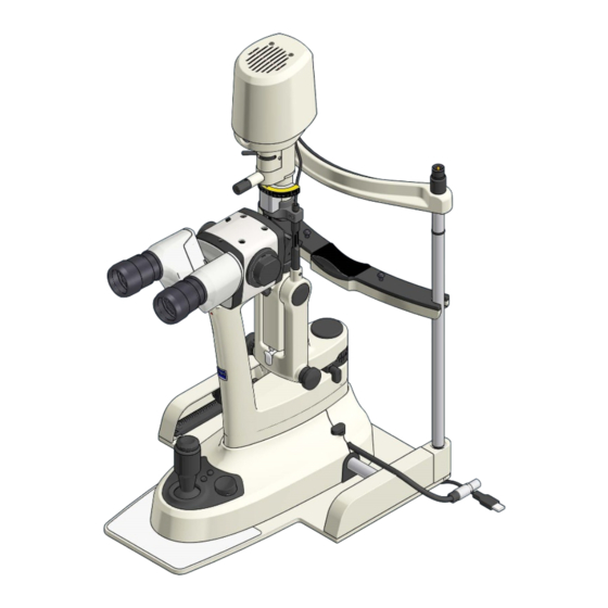
SL 800 General Information SL 800 Modules and Parts Projector / Illumination System Mirror Eyepieces with eyecups Tube Magnification Changer and Front Objective Microscope arm Joystick Base Plate Instrument Base with Operator Panel Instrument table with attached Power Module Rail system... -
Page 11: Section 2 - Checkout And Preventive Maintenance
Section 2 – Checkout and Preventive Maintenance 2.1 System Check-Out Procedure ................2 2.2 Preventative Maintenance Procedure ..............3 2.3.1 Perform the instrument check out .................. 3 2.3.2 Cleaning the rail system ....................4 2.3.3 Cleaning the front objective lens ..................5 2.3.4 Cleaning the mirror ...................... -
Page 12: System Check-Out Procedure
Checkout and Preventive Maintenance SL 800 2.1 System Check-Out Procedure The system check described below can be used in order to verify the proper function of the SL 800 after completion of any corrective maintenance activity. Step Check Procedure Expected Check Result... -
Page 13: Preventative Maintenance Procedure
Checkout and Preventive Maintenance 2.2 Preventative Maintenance Procedure 2.3.1 Perform the instrument check out The system check described below can be used in order to verify the proper function of the SL 800 in case of preventative maintenance activities. Step Check Procedure... -
Page 14: Cleaning The Rail System
Checkout and Preventive Maintenance SL 800 2.3.2 Cleaning the rail system Tools and aids: Air blower with valve Optional, a small paintbrush Procedure 1) Remove the rail cover on each side, one after the other by pushing them manually parallel outwards, see Fig. -
Page 15: Cleaning The Front Objective Lens
SL 800 Checkout and Preventive Maintenance 2.3.3 Cleaning the front objective lens Tools and aids: Air blower with valve Optic cleaning mixture L or an equivalent optic cleaning liquid Cotton swaps or alternative cleaning swaps Note It is recommended to start with the air blower. If using canned compressed air, do not allow liquid propellant to strike optical surfaces, as spotting may result on the surfaces. -
Page 16: Cleaning The Mirror
Checkout and Preventive Maintenance SL 800 2.3.4 Cleaning the mirror Tools and aids: Air blower with valve Optic cleaning mixture L or an equivalent optic cleaning liquid Cotton swaps, alternative cleaning swaps or cleaning tissues Hand gloves Note It is recommended to start with the air blower. -
Page 17: Firmware Update
6) Remove the USB flash drive. 7) Reconnect the removed USB cables to the corresponding USB sockets at the power module. 8) Switch the SL 800 on at the power module unit to continue working with the device. SM-30-4072 Service Manual... -
Page 18: Create Log-Files
Writing of the SL 800 log file starts automatically. After a few seconds, the SL 800 confirms completion of log file creation by three beeps. 4) Switch off the SL 800 at the power supply unit after the log life has been written successfully. 5) Remove the USB flash drive. -
Page 19: Electrical Safety Test
62353. When performing the inspection, observe the following instructions. Procedure 1) Perform a system check out, see Chapter 2.1, to ensure the SL 800 is in proper condition. 2) If there are doubts about the effectiveness of the insulation (such as multiple triggering... -
Page 21: Section 3 - Parts Removal Replacement
Section 3 – Parts Removal Replacement 3.1 Observation Unit ....................2 3.1.1 Eyepiece Replacement ....................2 3.1.2 Binocular Tube Replacement ..................3 3.1.3 Comfort Interface Replacement ..................4 3.1.4 Fundus VarioView Replacement ..................5 3.1.5 Magnification changer (manual/motorized) Replacement ..........6 3.1.6 Front objective lens replacement .................. -
Page 22: Observation Unit
Parts Removal Replacement SL 800 3.1 Observation Unit 3.1.1 Eyepiece Replacement Procedure 1) Pull the eyepiece towards the operator side, see Fig. 7 while holding the tube. Reassembly 1) Reassemble in reverse order; make sure the eyepiece is fully seated. -
Page 23: Binocular Tube Replacement
SL 800 Parts Removal Replacement 3.1.2 Binocular Tube Replacement Tools and aids: 1.5 mm hex key Precondition: The Power Module has been switched off Procedure 1) Support the tube using one hand. 2) Loose, but do not remove the fixation screw (1.5 mm hex key) using the other hand. -
Page 24: Comfort Interface Replacement
Parts Removal Replacement SL 800 3.1.3 Comfort Interface Replacement Tools and aids: 3 mm hex key Precondition: The Power Module has been switched off The binocular tube has been removed Procedure 1) Loose, but do not remove the 3 fixation screws (3 mm hex key), see Fig. -
Page 25: Fundus Varioview Replacement
SL 800 Parts Removal Replacement 3.1.4 Fundus VarioView Replacement Tools and aids: 1.5 mm hex key 3 mm hex key 4 mm hex key Precondition: The Power Module has been switched off Accessories, e.g. the Tonometer has been removed... -
Page 26: Magnification Changer (Manual/Motorized) Replacement
Parts Removal Replacement SL 800 3.1.5 Magnification changer (manual/motorized) Replacement Tools and aids: 1.5 mm hex key 3 mm hex key 4 mm hex key Precondition: The Power Module has been switched off Procedure 1) Support the tube using the other hand. - Page 27 SL 800 Parts Removal Replacement Reassembly 1) Reassemble in reverse order. NOTE When attaching to observation unit to the arm, take care of the cable position. Do not harm or pinch the cable isolation. Fig. 17: Front objective screws SM-30-4072...
-
Page 28: Front Objective Lens Replacement
Parts Removal Replacement SL 800 3.1.6 Front objective lens replacement Tools and aids: 3 mm hex key Precondition: The Power Module has been switched off In case of an installed Fundus VarioView unit, please remove the binocular tube and the entire observation unit first, 3.1.4. -
Page 29: Illumination Unit
SL 800 Parts Removal Replacement 3.2 Illumination Unit 3.2.1 Illumination Unit Cover Replacement Tools and aids: Torx 10 Precondition: The Power Module has been switched off Procedure 1) Remove 2 fixation screws on top of the cover (Torx 10), see Fig. -
Page 30: Illumination Led Assembly Replacement
Parts Removal Replacement SL 800 3.2.2 Illumination LED Assembly Replacement Tools and aids: Torx 10 Precondition: The Power Module has been switched off Procedure 1) Remove 2 fixation screws on top of the cover (Torx 10), see Fig. -
Page 31: Instrument Base And Headrest
SL 800 Parts Removal Replacement 3.3 Instrument Base and Headrest 3.3.1 Operator Panel Replacement Tools and aids: 1.5 mm Hex Key Precondition: Identify the correct operator panel version as replacement item The Power Module has been switched off Procedure 1) Carefully loosen the fixation screw (1.5 mm... -
Page 32: Instrument Base Cover Replacement
Parts Removal Replacement SL 800 3.3.2 Instrument Base Cover Replacement Tools and aids: Torx 10 Precondition: The Power Module has been switched off The Operator Panel, see Chapter 3.3.1 has been removed Procedure 1) Remove the fixation screw at the patient side, see Fig. -
Page 33: Joystick Replacement
SL 800 Parts Removal Replacement Reassembly 1) Reassemble in reverse order. Fig. 30: Instrument base main cover removal 3.3.3 Joystick Replacement Tools and aids: Retaining Ring Pliers Torx 10 Precondition: The Power Module has been switched off ... -
Page 34: Joystick Button Replacement
Parts Removal Replacement SL 800 3.3.4 Joystick Button Replacement Tools and aids: 1.5 mm Hex Key 11 mm Hex Socket Key Precondition: The Power Module has been switched off Procedure 1) Carefully loosen the joystick cap fixation screw (1.5 mm Hex Key), but do not remove... -
Page 35: Rail System Replacement
1) Remove the rail cover on each side, one after the other by pushing them manually parallel outwards, see Fig. 2) Remove the SL 800 instrument base. 3) Remove two fixation screws (Torx 10) of the rail, see Fig. 4) Remove the rail. -
Page 36: Head Rest Replacement
Precondition: The Power Module has been switched off Remove the SL 800 inclusive baseplate from any instrument table Procedure 1) Disconnect the fixation light cable from power supply, if the fixation light connector is part of the head rest. -
Page 37: Chin Cup Replacement
SL 800 Parts Removal Replacement 3.3.7 Chin Cup Replacement Tools and aids: Torx 10 Procedure 1) Carefully remove the three fixation screws (Torx 10) of the chin cup, see Fig. 2) Remove the chin cup. Fig. 41: Chin cup replacement Reassembly 1) Reassemble in reverse order. -
Page 38: Power Module Replacement
Parts Removal Replacement SL 800 3.4 Power Module Replacement Procedure 1) Disconnect all cables. 2) Remove all 4 fixation screws, e.g. if the power module is attached to an instrument table. Reassembly 1) Reassemble in reverse order. 2) Restore all positions of the DIP switch... -
Page 39: Section 4 - Adjustment And Calibration
Section 4 – Adjustment and Calibration 4.1 Firmware Update ....................2 4.2 Create Log Files....................3 SM-30-4072 Service Manual Confidential and Proprietary Version 02, 2019-10-24 4 - 1 Order No. 2330-705... - Page 40 6) Remove the USB flash drive. 7) Reconnect the removed USB cables to the corresponding USB sockets at the power module. 8) Switch the SL 800 on at the power module unit to continue working with the device. Service Manual...
- Page 41 The creation and export of log files can be performed by any user and customer (see SL 800 user manual) and is helpful to support a phone fix activity or to prepare an onsite troubleshooting session.
-
Page 42: Section 5 - Troubleshooting Error Codes
Section 5 – Troubleshooting Error Codes 5.1 Log file structure ....................2 5.2 Log file error code list ..................3 5.3 Tool List ....................... 7 SM-30-2330-705 Service Manual Confidential and Proprietary Version 02, 2019-10-24 5 - 1 Order No. 2330-705... - Page 43 The SL 800 log file contains information on configuration, status of individual modules or any errors that may have occurred. The log file is very helpful for preparing a ZEISS service call in the event of a technical problem with the device.
- Page 44 SL 800 Troubleshooting Error Codes 5.2 Log file error code list The error code list will be gradually filled with appropriate actions to resolve the errors. Some errors can be eliminated by restarting the device. Please try the error correction measure step by step and create a new log file after the completion of each correction measure in order to check the solution.
- Page 45 Troubleshooting Error Codes SL 800 Error Error Name Module Error description Error Correction E_PwmError_USB_FAT_FS Power Module USB-Bus error: flash Check or replace drive cannot be connected USB flash detected drive, replace the Power Module E_Instrument Instrument CAN Bus error Replace the...
- Page 46 SL 800 Troubleshooting Error Codes Error Error Name Module Error description Error Correction E_Instrument Instrument Operator Panel Check all connections BaseaError_HW_I2C_COM_ADC Base error at the Operator Panel, Replace the Operator Panel, Replace the instrument E_Instrument Instrument Operator Panel Check all connections...
- Page 47 Troubleshooting Error Codes SL 800 Error Error Name Module Error description Error Correction E_ChrError_EEPROM_WRITE Microscope Microscope Replace the Microscope EEPROM errors E_ChrError_EEPROM_ID Microscope Microscope Replace the Microscope EEPROM errors E_ChrError_CHR_MOTOR_DR Microscope Cannot reach the Check all microscope IVING_TIMEOUT desired cable connections,...
- Page 48 SL 800 Troubleshooting Error Codes 5.3 Tool List Tool description Order Number Use of Tool Torx Set (6, 8, 10, 15, 20, 30) Complete Hex Set (1.5, 3, 4) Complete Hex Socket Key (11 mm) Joystick Button Side Cutters Misc. zip ties...
-
Page 49: Section 6 - Diagrams
Section 6 – Diagrams MOMENTARILY NO DOCUMENTATION AVAILABLE SM-30-4072 Service Manual Confidential and Proprietary Version 02, 2019-10-24 6 - 1 Order No. 2330-705... -
Page 50: Section 7 - Parts
Section 7 – Parts Spare parts, see icon: on selection bar... -
Page 51: Section 8 - Appendices
Section 8 – Appendices MOMENTARILY NO DOCUMENTATION AVAILABLE SM-30-4072 Service Manual Confidential and Proprietary Version 01, 2019-10-24 8 - 1 Order No. 2330-705...
Need help?
Do you have a question about the SL 800 and is the answer not in the manual?
Questions and answers