Table of Contents
Advertisement
Quick Links
Advertisement
Table of Contents

Related Manuals for ibidi 11920


Summary of Contents for ibidi 11920
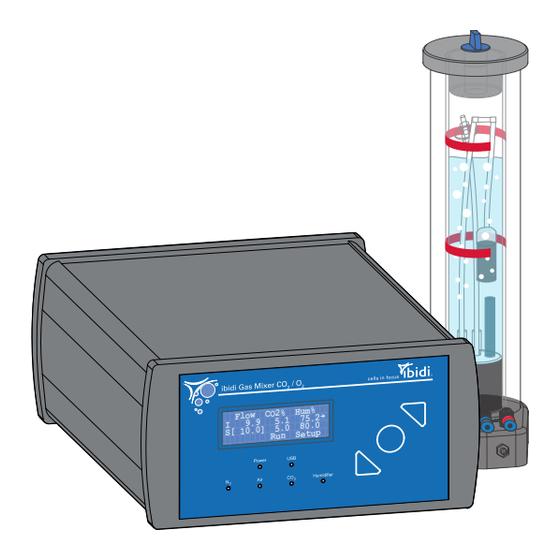
- Page 1 5. 1 9. 9 80 .0 5. 0 S[ 10 .0 ] Ru n Se tu p 11920 ibidi Gas Incubation System for CO – Blue Line 11922 ibidi Gas Incubation System for CO and O – Blue Line .com...
- Page 3 Gas Incubation System – Blue Line Instruction Manual Contact ibidi GmbH Lochhamer Schlag 11 82166 Gräfelfing Germany Phone: +49 89 / 520 46 17 - 0 Fax: +49 89 / 520 46 17 - 59 E-mail: info@ibidi.de Web: ibidi.com Version 2.3 (October 18, 2023)
-
Page 4: Table Of Contents
........2 Intended Use 3 Principle 4 Equipment Components of the ibidi Gas Incubation System – Blue Line ....Gas Mixer CO or CO . - Page 5 Gas Incubation System – Blue Line Instruction Manual 7 Maintenance Disinfection and Cleaning ........
-
Page 6: Preamble
1 Preamble 1.1 Introduction This manual is your guide for using the ibidi Gas Incubation System – Blue Line for cell culture experiments on an optical microscope. It instructs first-time users on how to use the instrument, and serves as a reference for experienced users. -
Page 7: Nomenclature
Gas Incubation System – Blue Line Instruction Manual 1.3 Nomenclature The ibidi Gas Incubation System – Blue Line consists of the following three main components: Gas Mixer Humidifying Column Heated Tubing Package 1.4 Specifications Table 1: Specifications of the ibidi Gas Incubation System – Blue Line... - Page 8 Gas Incubation System – Blue Line Instruction Manual Table 1: (continued) Outer Dimensions and Characteristics of the Components Gas Mixer 90 × 170 × 230 mm 2230 g/4.9 lbs Humidifying Column 70 × 110 × 300 mm 660/710/790 g /1.45/1.57/1.74 lbs (empty/min/max) Heated Tubing Package 0.6 m (between Controller and Column)
- Page 9 Instruction Manual Table 1: (continued) Control Control range 1–21 % (note: settings below 1 % are less accurate and a typical minimum value in an ibidi Heating Chamber is 0.5 % O Accuracy ±0.2 % (typical) ±0.7 % (max.) Resolution 0.1 %...
-
Page 10: Disclaimer
Instruction Manual 1.5 Disclaimer • ibidi shall not be held liable, either directly or indirectly, for any damage incurred as a result of product use. • The contents of this manual are subject to change without notice for product improvement. - Page 11 • Avoid vibrations from vacuum pumps, centrifuges, electric motors, processing equipment, and machine tools. • Avoid dust and corrosive gas. Do not install the ibidi Gas Incubation System – Blue Line where it could be exposed to high levels of dust or to outside air or ventilation outlets.
-
Page 12: Limited Warranty
Products manufactured by ibidi, unless otherwise specified, are warrantied for a period of one year from the date of shipment to be free of defects in materials and workmanship. If any defects in the product are found during this warranty period, ibidi will repair or replace the defective part(s) or product free of charge. -
Page 13: Waste Disposal - Weee/Rohs Compliance Statement
(Restriction on the use of Hazardous Substances, RoHS). 1.10.1 EU Directive WEEE The ibidi Gas Incubation System – Blue Line must be disposed of in compliance with the WEEE Directive 2012/19/EC. This symbol on the product is in accordance with the European Union’s Waste Electrical and Elec- tronic Equipment (WEEE) Directive. -
Page 14: Regulatory Statement
Gas Incubation System – Blue Line Instruction Manual 1.11 Regulatory Statement EG-Konformitätserklärung EC Declaration of Conformity Wir / We ibidi GmbH Lochhamer Schlag 11 D-82166 Gräfelfing erklären hiermit die Übereinstimmung des genannten Produktes mit der Richtlinie 2014/35/EU - Niederspannungsrichtlinie und mit der Richtlinie 2014/30/EU über die Elektromagnetische Verträglichkeit. -
Page 15: Intended Use
It is intended to be used with stage top incubators and can be applied on various microscopes. The ibidi Gas Incubation System – Blue Line mixes the required gas ratios in the output and actively humidifies this mixed gas output before the gas enters the Incubation Chamber. -
Page 16: Principle
Dry gas mix Valve Humidified gas mix regulation Feedback control Figure 2: Schematic view of the ibidi Stage Top Incubation System, combining the Heating System with the Gas Incubation System. RH: relative humidity. © ibidi GmbH Version 2.3 (October 18, 2023) - Page 17 The independently controlled Heated Lid of the ibidi Heating System prevents condensation during live cell imaging (Figure 3). By heating the lid to a temperature higher than the plate, a vertical temperature gradient is created.
-
Page 18: Equipment
Instruction Manual 4 Equipment The ibidi Gas Incubation System – Blue Line is delivered with the complete set of cables and tubing needed for the operation of the system. 4.1 Components of the ibidi Gas Incubation System – Blue Line An overview of the different ibidi Gas Incubation System –... -
Page 19: Gas Mixer Co 2 Or Co 2 /O 2
Gas Incubation System – Blue Line Instruction Manual Table 3: Overview of the components of the ibidi Gas Incubation System, for CO – Blue Line and ibidi Gas Incubation System, for CO – Blue Line. The drawings are not to scale. - Page 20 4.2 Gas Mixer CO or CO The Gas Mixer is the gas mixing and control unit of the ibidi Gas Incubation System – Blue Line. There are two versions of the Gas Mixer controlling either the amount of CO or the amount of both and O .
-
Page 21: Humidifying Column
Gas Incubation System – Blue Line Instruction Manual Figure 5: Back view of the Gas Mixer. 4.3 Humidifying Column To avoid evaporation and drying out of the probe, the Humidifying Column humidifies the gas stream flowing into the Incubation Chamber. Part of the mixed gas output is guided through the column. The water inside the column is warmed up for higher humidity uptake. -
Page 22: Heated Tubing Package
Gas Incubation System – Blue Line Instruction Manual The Humidifying Column has two color-coded gas connections (input and output) as well as an elec- tric plug for the heating of the column (connection see Section 5.1.2). On top of the column is an opening for (re-)filling it with ultra-pure water (see Section 5.2). -
Page 23: Humidity Sensor
Gas Incubation System – Blue Line Instruction Manual 4.5 Humidity Sensor The humidity sensor measures the humidity inside the incubation chamber, enabling fast, active humidity control. It is fixed into the side wall of the Heated Lid of the Incubation Chamber (Figure 8). - Page 24 Gas Incubation System – Blue Line Instruction Manual Polymer block with humidity sensor Spacer nut Through-hole Counter nut Figure 10: Installation of the humidity sensor to the side wall of the Heated Lid. CAUTION – Make sure that the polymer block is NOT in contact with the Heated Lid.
-
Page 25: Operation
Computer (optional) Heated Tubing Package Figure 11: Connection of the components of the ibidi Gas Incubation System – Blue Line and Heating System. CAUTION – Do not place the Gas Mixer and Humidifying Column on the microscope stage! The vibration might disturb the measurement. -
Page 26: Connection To The Gas Supply
Gas Incubation System – Blue Line Instruction Manual To operate the ibidi Gas Incubation System – Blue Line, perform the following steps in the indicated order: 1. Place the Gas Mixer and Humidifying Column onto the microscope table next to the microscope stand. - Page 27 Gas Incubation System – Blue Line Instruction Manual Table 5: Available connections and color code in the two different Gas Mixer versions Gas Input Gas Pressure Tubing Color from source with pressure reducer (labline / 1 bar/14.5 psi blue...
-
Page 28: Connection Of The Heated Tubing Package And The Humidifying Column
Gas Incubation System – Blue Line Instruction Manual Figure 16: How to connect the gas tubing to a pressure reducing valve from a gas line, compressor, or gas bottle. A push-in fitting for 6 mm O.D. tubing is recommended. - Page 29 11/201 8 Product ion date: Figure 17: Connection of the Heated Tubing Package to the ibidi Gas Incubation System – Blue Line. CAUTION – Do not disconnect the Heated Tubing while the Gas Mixer is running. The resulting sudden change of pressure may damage the Gas Mixer.
-
Page 30: Connection Of Humidity Sensor Cable
The humidity sensor should be mounted in the Heated Lid of the Heating System (see Section 4.5). To operate the ibidi Gas Incubation System – Blue Line with humidity control, the humidity sensor cable must be connected between the Gas Mixer and the humidity sensor. -
Page 31: Re)-Filling The Humidifying Column
Gas Incubation System – Blue Line Instruction Manual 5.2 (Re)-Filling the Humidifying Column Before the first use, the Humidifying Column must be filled with 130 ml of ultra-pure water. During operation, the column should always be refilled before the water level falls below the minimum mark. -
Page 32: Switching On The System
Column (max. 60°C/140°F) and the Heated Tubing Package (max. 50°C/122°F outside). To turn off the ibidi Gas Incubation System, first switch off the Gas Mixer and then close all sources for gas supply. 5.4 Setting Parameters With the Front Display All control parameters can be manually set on the controller using the buttons and the display on the front panel. -
Page 33: Run/Stop Mode
“Run” (= system is running) or “Stop” (= system is not running) (Figure 21). Figure 21: Main display indicating “Run”. 5.4.2 Incubation Parameters Table 7: Recommended parameters for the operation of the ibidi Gas Incubation System – Blue Line Parameter Recommended Values 5–10 % depending on buffer... -
Page 34: Setup Menu
Gas Incubation System – Blue Line Instruction Manual regulation/hypoxia (Gas Mixer for CO only) To generate hypoxia conditions, set the oxy- gen to the target value. The O will be replaced by nitrogen (N ) until the set value is reached. - Page 35 Gas Incubation System – Blue Line Instruction Manual 3. Select “On” or “Off” and confirm with the round button. 4. To move on navigate to “Return” and press the round button. Table 8: Channel numbers are dedicated as follows:...
-
Page 36: Incucontrol Software
Gas Incubation System – Blue Line Instruction Manual 6 IncuControl Software The Gas Mixer has a USB interface for computer control and data logging. For this purpose, ibidi provides the IncuControl software version (3.x.x) that can be downloaded from the ibidi website. -
Page 37: Maintenance
Gas Incubation System – Blue Line Instruction Manual 7 Maintenance 7.1 Disinfection and Cleaning 7.1.1 Wiping the Outer Surface To clean the Gas Mixer and Humidifying Column from the outside, switch off the Gas Mixer and disconnect all cables and tubing. Leave the instrument to cool down for approximately 5 minutes. Use only dry cloth or a cloth dampened with water (ultrapure) or common lab disinfection solutions that are based on quaternary ammonium compounds (e.g., Barrycidal 36 or Pharmacidal). -
Page 38: Troubleshooting
Gas Incubation System – Blue Line Instruction Manual 8 Troubleshooting 8.1 Controller Display Errors Error Description Possible Cause Possible Solution The display does not work, although Power supply inter- Check the power supply the power supply is connected. rupted. -
Page 39: Co 2 Channel Readings
Gas Incubation System – Blue Line Instruction Manual (Table continued) Defective flow sensor or Check if gas bubbles form inside the valve. Humidifying Column. Contact ibidi technical support. Gas flow reading is un- Incorrect set values. Please check set values of flow, CO... -
Page 40: Channel Readings
Gas Incubation System – Blue Line Instruction Manual (Table continued) Gas line restriction. Make sure that the gas lines are not blocked or kinked. Please note: The sys- tem must be restarted after the interrup- tion is removed. The N... -
Page 41: Humidity Channel Readings
Gas Incubation System – Blue Line Instruction Manual (Table continued) Insufficient Set N gas pressure at 1 bar (14,5 psi). pressure. The CO concentra- Make sure the ratio of CO concentra- tions are set at incor- tion is set correctly. -
Page 42: Humidifying Column
Gas Incubation System – Blue Line Instruction Manual (Table continued) Heated Tubing pack- Check if any damage to the Heated Tubing age is damaged and Package is seen. Contact ibidi technical sup- gas escapes. port. Humidifying Column Make sure that the column is properly sealed not closed properly. -
Page 43: Focus Not Stable
Depending on the incubating conditions, small volumes might evaporate quickly, especially during long-term experiments. If you have an actively controlled humidifying device (e.g. ibidi Gas Incubation System), increase the set value for humidity. Additionally, we suggest using silicone oil (e.g. Anti- Evaporation Oil, ibidi, 50051) to decrease evaporation. - Page 44 GmbH Lochhamer Schlag 11 82166 Gräfelfing Germany Toll free within Germany: Phone: 0800 / 00 11 11 28 Fax: 0800 / 00 11 11 29 International calls: Phone: +49 89 / 520 46 17 - 0 Fax: +49 89 / 520 46 17 - 59 E-Mail: info@ibidi.com...
Need help?
Do you have a question about the 11920 and is the answer not in the manual?
Questions and answers