Table of Contents

Related Manuals for ibidi 11920


Summary of Contents for ibidi 11920
- Page 1 CO 2% Hu m% Fl ow 75 .2 5. 1 9. 9 80 .0 5. 0 S[ 10 .0 ] Ru n Se tu p 11920 ibidi Gas Incubation System for CO 11922 ibidi Gas Incubation System for CO and O www.ibidi.com...
- Page 2 Gas Incubation System Version 2.2 (May 15, 2019) Instruction Manual...
- Page 3 Gas Incubation System Contact ibidi GmbH Lochhamer Schlag 11 82166 Gr¨ a felfing Germany Phone: +49 89 / 520 46 17 - 0 Fax: +49 89 / 520 46 17 - 59 E-mail: info@ibidi.de Internet: ibidi.com Instruction Manual Version 2.2 (May 15, 2019)
-
Page 4: Table Of Contents
Gas Incubation System Contents 1 Preamble 1.1 Introduction ......... . . 1.2 Safety Symbols . - Page 5 Gas Incubation System 5 Operation 5.1 Installation and Connection ........5.1.1 Connection to the Gas Supply .
-
Page 6: Preamble
This manual should be easily accessible to the oper- ator at all times during instrument operation. If this manual gets lost, order a replacement from www.ibidi.com. To ensure safe operation, the Gas Incubation System must only be operated with the supplied com- ponents and according to the instruction manual. -
Page 7: Nomenclature
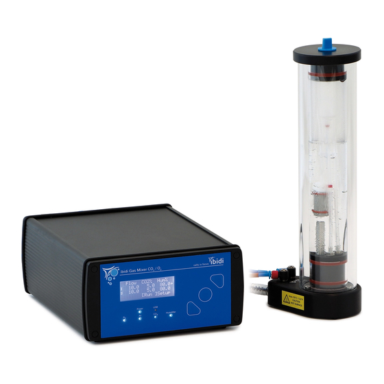
Gas Incubation System 1.3 Nomenclature Gas Mixer Humidifying Column Heated Tubing Package 1.4 Specifications Table 1 – Specifications of the Gas Incubation System Electrical Specifications Power Supply Protection class International protection marking IP 20 (IEC 60529) Overvoltage category External power supply AC 100-240 V, 50/60 Hz, 1.4 A Input line voltage Gas Mixer DC 24 V, 5 A, 120 W... - Page 8 CO measurement to combat sensor drift. Control Control range 1-21% (Note: Settings below 1% are less accurate and a typi- cal minimum value in an ibidi Heating Chamber is 0.5% O Accuracy ±0.2% (typical) ±0.5% (max.) Resolution 0.1%...
- Page 9 Gas Incubation System Table 1 – (continued) cross sensitivity The O sensor has some cross–sensitivity to CO gas at 0% concentrations. This manifests as an offset in the mea- sured O concentration, with typical values shown in the ta- ble below: Conc.
-
Page 10: Disclaimer
Gas Incubation System 1.5 Disclaimer • ibidi shall not be held liable, either directly or indirectly, for any damage incurred as a result of product use. • The contents of this manual are subject to change without notice for product improvement. -
Page 11: Regulatory Statement
Gas Incubation System • Only ibidi technical staff and technical staff instructed by ibidi are permitted to open and ser- vice the Gas Incubation System. • The external power supply should not be brought into contact with moisture. If the housing is damaged, the external power supply should not be used. -
Page 12: Limited Warranty
Products manufactured by ibidi, unless otherwise specified, are warrantied for a period of one year from the date of shipment to be free of defects in materials and workmanship. If any defects in the product are found during this warranty period, ibidi will repair or replace the defective part(s) or product free of charge. -
Page 13: Repairing The Gas Incubation System
Gas Incubation System 1.10 Repairing the Gas Incubation System For inquiries concerning repair service, contact the ibidi service personnel and provide the model name and serial number of your system. ibidi GmbH Service Hotline: service@ibidi.com CAUTION Do not try to repair the Gas Incubation System by yourself. Disassembly of the Gas Incubation System is not allowed. -
Page 14: Intended Use
Incubation System mixes the required gas ratios in the output and actively humidifies this mixed gas output before the gas enters the incubation chamber. Two versions of the Gas Incubation System are available: the ibidi Gas Incubation System for CO and the ibidi Gas Incubation System for CO and O . -
Page 15: Equipment
Additional to all parts of #11920: Gas Tubing for N Dead end tubing Table 3 – Overview of the components of the ibidi Gas Incubation System for CO and ibidi Gas Incubation System for CO . The parts that are only available in the CO version are marked with an asterisk (*). - Page 16 Gas Incubation System Table 3 – (continued) Component Name Drawing Humidifying Column Heated Tubing Package: cables and tubing to connect the gas outlet of the Gas Mixer, gas ports of the Humidifying Column and the gas inlet of the Heated Lid Gas tubing for CO , Air and N Dead end tubing to close the N...
- Page 17 4.2 Gas Mixer CO or CO The Gas Mixer is the gas mixing and control unit of the ibidi Gas Incubation System. There are two versions of the Gas Mixer controlling either the amount of CO or the amount of both CO...
-
Page 18: Humidifying Column
Gas Incubation System Figure 3 – Back view of the Gas Mixer. 4.3 Humidifying Column The Humidifying Column provides a water reservoir to humidify the mixed gas. Part of the mixed gas output is guided through the column. The water inside the column is warmed up for higher humidity uptake. -
Page 19: Humidity Sensor
Gas Incubation System are combined in the tubing leading to the stage top incubator. By varying the flow rates of the two gas streams, the humidity can be controlled. The gas tubing carrying humidified gas is heated up to avoid condensation. For this purpose, a heating wire is inserted in the tubing. - Page 20 Gas Incubation System To ensure accurate humidity measurements , the humidity sensor must be mounted securely in the plastic through-hole in the side of the Heated Lid. To do this, please follow the steps below: 1. Check that the spacer nut is fixed on the humidity sensor’s threaded connector. 2.
-
Page 21: Operation
Gas Incubation System 5 Operation The components must be assembled in the following order: 1. Connect all tubing and cables. 2. Apply 1 bar (14.5 psi) to the connected gas tubing. 3. Switch on the Gas Mixer. Caution! Not maintaining this order may lead to device malfunction or damage! The procedure is explained in detail in the following sections. -
Page 22: Connection To The Gas Supply
Gas Incubation System 5.1.1 Connection to the Gas Supply The gases from the bottle or laboratory gas line need to be connected to the Gas Mixer with the OD 6 mm polyurethane tubing of the respective color. This tubing is delivered with the system. Table 5 –... -
Page 23: Connection Of The Heated Tubing Package And The Humidifying Column
Gas Incubation System Position „OFF“ Figure 11 – Close the N port of the Gas Mixer with the dead end tubing if not needed (CO version only). Warning! Only disconnect the tubing when there is no pressure on the gas line. First, switch off the pressure from the gas line. -
Page 24: Connection Of Humidity Sensor Cable
Gas Incubation System 5. To connect the mixed and humidified gas output to the Heated Chamber, screw the Luer Lock connector into the metal adapter that is fixed in the wall of the Heated Lid. Figure 12 – Connection of the Heated Tubing Package to the Gas Incubation System. Caution! Do not disconnect the Heated Tubing while the Gas Mixer is running. -
Page 25: Connection Of Power Supply (And Usb Optionally)
Gas Incubation System Figure 13 – Connection of the humidity sensor cable to the humidity sensor. 5.1.4 Connection of Power Supply (and USB optionally) To finish the setup, the power supply must be connected. Optionally, the USB cable can be used to connect the Gas Mixer to an external computer. -
Page 26: Switching On The System
Gas Incubation System Open the blue stopper on top of the column and use a wash bottle to fill it with ultra-pure water. The water level must be in between the minimum and maximum mark (Figure 14). The re-filling of the Humidifying column can be done during operation, without stopping the Gas Mixer. -
Page 27: Setting Parameters In The Front Display
Gas Incubation System For most applications, we recommend using the values given in Table 7. The full specification range is indicated in the specifications (Section 1.4). Caution! Be aware that when the system is switched on, some parts of the tubing are actively heated: The Humidifying Column base (max. -
Page 28: Incubation Parameters
Gas Incubation System 5.4.2 Incubation Parameters Table 7 – Recommended parameters for the operation of the Gas Incubation System Parameter Recommended Values 5–10% depending on buffer * (%) 20% (see Figure 17) Humidity (%) 90–95% Flow rate 10 l/h Column Temperature (°C) 50°C *for CO version only... -
Page 29: Setup Menu
Gas Incubation System 5.4.3 Setup Menu The Setup menu offers the possibility to change the settings of the individual channels and the dis- play. For standard operation no changes need to be made. Enter the setup menu by navigating to the ”Setup”... - Page 30 Gas Incubation System <Alarms> Setup Channel = 4 High = 42°C = 36°C Figure 19 – Alarm settings dialog Preferences Set the brightness and contrast of the display in the preferences menu. <Preferences> Setup Backlight = 65 Contrast = 15 Return Figure 20 –...
-
Page 31: Incucontrol Software
Gas Incubation System 6 IncuControl Software The Gas Mixer has a USB interface for computer control and data logging. For this purpose, ibidi provides the IncuControl software that comes with the controller or can be downloaded from the ibidi website. -
Page 32: Maintenance
Gas Incubation System 7 Maintenance 7.1 CO Sensor Auto-Recalibration At least once per week the Gas Mixer must be turned off for 5 minutes. This is necessary for the flow sensor’s onboard automatic calibration routine, which needs an atmospheric CO measurement to compensate sensor drift. -
Page 33: Troubleshooting
Depending on the incubating conditions, small volumes might evaporate quickly, especially during long-term experiments. If you have an actively controlled humidifying device (e.g. ibidi Gas Incuba- tion System), increase the set value for relative humidity. Additionally, we suggest using silicone oil (e.g. -
Page 34: Gas Pressure Too Low
Check the temperature of the chamber (Heated Lid and Heated Plate). Make sure the humidity sensor is not in contact with the Heated Lid. In case of condensation, decrease the humidity and air-dry the incubator if necessary. Please contact ibidi at techsupport@ibidi.com for further troubleshooting help. - Page 35 Gas Incubation System Instruction Manual Version 2.2 (May 15, 2019)
- Page 36 GmbH Lochhamer Schlag 11 82166 Gräfelfing Germany Toll free within Germany: Phone: 0800 / 00 11 11 28 Fax: 0800 / 00 11 11 29 International calls: Phone: +49 89 / 520 46 17 - 0 Fax: +49 89 / 520 46 17 - 59 E-Mail: info@ibidi.com...
Need help?
Do you have a question about the 11920 and is the answer not in the manual?
Questions and answers