Table of Contents
Advertisement
Quick Links
Instruction Manual
ibidi Gas Incubation System – Silver Line
for use with ibidi Heating System Slide / Dish – Silver Line
11921 ibidi Gas Incubation System, CO
11923 ibidi Gas Incubation System, CO
Version 1.0
/ O
ibi di Ga s Mi xe r
ibi di Ga s Mi xe r
CO
CO
/ O
2
2
2
2
CO 2% Hu m%
CO 2% Hu m%
Fl ow
Fl ow
75 .2
75 .2
5. 1
5. 1
9. 9
9. 9
I
I
80 .0
80 .0
5. 0
5. 0
S[ 10 .0 ] Ru n
S[ 10 .0 ] Ru n
Se tu p
Se tu p
12110, 12720,
12722, 12111
– Silver Line
2
/ O
– Silver Line
2
2
.com
Advertisement
Table of Contents

Related Manuals for ibidi 12110


Summary of Contents for ibidi 12110
- Page 1 Instruction Manual ibidi Gas Incubation System – Silver Line for use with ibidi Heating System Slide / Dish – Silver Line 12110, 12720, 12722, 12111 ibi di Ga s Mi xe r ibi di Ga s Mi xe r CO 2% Hu m%...
- Page 2 Gas Incubation System – Silver Line Version 1.0 (June 1, 2022) Instruction Manual...
- Page 3 Gas Incubation System – Silver Line Contact ibidi GmbH Lochhamer Schlag 11 82166 Gr¨ a felfing Germany Phone: +49 89 / 520 46 17 - 0 Fax: +49 89 / 520 46 17 - 59 E-mail: info@ibidi.de Internet: ibidi.com Instruction Manual Version 1.0 (June 1, 2022)
-
Page 4: Table Of Contents
........2 Intended Use 3 Principle 4 Equipment 4.1 Components of the ibidi Gas Incubation System – Silver Line ....4.2 Gas Mixer CO or CO . - Page 5 Gas Incubation System – Silver Line 5 Operation 5.1 Installation and Connection ........
-
Page 6: Preamble
Heating System Slide/Dish – Silver Line (#12110, #12720, #12722, #12111). For use of the ibidi Gas Incubation System – Silver Line with the ibidi Heating System 4 Slides – Silver Line (#12130, #12131) or ibidi Heating System Multiwell Plate – Silver Line (#12150, #12724, #12726, #12151) please refer to the instruction manual “for use with the ibidi Heating System 4 Slides... -
Page 7: Nomenclature
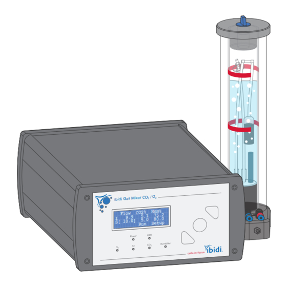
Gas Incubation System – Silver Line 1.3 Nomenclature The ibidi Gas Incubation System – Silver Line consists of the following three main components: ibidi Gas Mixe r CO CO2 % Hum % Flo w 75. 2 80. 0 S[ 10. 0] Run... - Page 8 ±(0.2%vol. + 3% of reading) e.g. ±0.35% at 5% CO concen- tration Resolution 0.1% Control Control range 1–21% (note: settings below 1% are less accurate and a typ- ical minimum value in an ibidi Incubation Chamber is 0.5% Version 1.0 (June 1, 2022) Instruction Manual...
- Page 9 Gas Incubation System – Silver Line Table 1: (continued) Accuracy ±0.2%vol. (typical) ±0.7%vol. (max.) Resolution 0.1% Heat-up time Five minutes before proper operation of sensor cross-sensitivity The O sensor has some cross-sensitivity to CO at 0% O This manifests as an offset in the measured O...
-
Page 10: Disclaimer
Gas Incubation System – Silver Line 1.5 Disclaimer • ibidi shall not be held liable, either directly or indirectly, for any damage incurred as a result of product use. • The contents of this manual are subject to change without notice for product improvement. - Page 11 • Avoid dust and corrosive gas. Do not install the ibidi Gas Incubation System – Silver Line where it could be exposed to high levels of dust or to outside air or ventilation outlets. • Install the ibidi Gas Incubation System – Silver Line in a location that enables easy access for maintenance.
-
Page 12: Limited Warranty
Products manufactured by ibidi, unless otherwise specified, are warrantied for a period of one year from the date of shipment to be free of defects in materials and workmanship. If any defects in the product are found during this warranty period, ibidi will repair or replace the defective part(s) or product free of charge. -
Page 13: Repairing The Ibidi Gas Incubation System - Silver Line
– Do not try to repair the ibidi Gas Incubation System – Silver Line by yourself. Disassembly of the ibidi Gas Incubation System – Silver Line is not allowed. Disassembly poses a risk of personal injury or damage to the devices. Contact ibidi technical support if there is a need to disassemble a device. -
Page 14: Regulatory Statement
Gas Incubation System – Silver Line 1.11 Regulatory Statement EG-Konformitätserklärung EC Declaration of Conformity Wir / We ibidi GmbH Lochhamer Schlag 11 D-82166 Gräfelfing erklären hiermit die Übereinstimmung des genannten Produktes mit der Richtlinie 2014/35/EU - Niederspannungsrichtlinie und mit der Richtlinie 2014/30/EU über die Elektromagnetische Verträglichkeit. -
Page 15: Intended Use
The Gas Incubation System mixes the required gas ratios in the output and actively humidifies this mixed gas output before the gas enters the incubation chamber. Two versions of the ibidi Gas Incubation System – Silver Line are available: the ibidi Gas Incubation System, CO –... - Page 16 40 °C 34 °C 37 °C 37 °C Heated Plate Heated Plate Figure 3: The ibidi Heating System prevents condensation on the cell culture vessel lid, as well as on the Heated Lid itself. Version 1.0 (June 1, 2022) Instruction Manual...
-
Page 17: Equipment
4.1 Components of the ibidi Gas Incubation System – Silver Line An overview of the different ibidi Gas Incubation System – Silver Line versions is given in this sec- tion. Table lists all available options of the ibidi Gas Incubation System – Silver Line and Table shows all included components. -
Page 18: Gas Mixer Co Or Co
Gas Incubation System – Silver Line Table 3: (continued) Component Name Drawing Humidifying Column Heated Tubing Package: cables and tubing to connect the gas outlet of the Gas Mixer, gas ports of the Humidifying Column and the gas inlet of the Heated Lid... - Page 19 Gas Incubation System – Silver Line ibidi Gas Mixer CO Flow CO2% Hum% 75.2 S[ 10.0] 80.0 Setup Figure 4: Front view of the Gas Mixer. The LEDs on the front indicate the status of the channels: connection to the power supply, connection to the USB, gas control, and humidity control (Figure 4).
-
Page 20: Humidifying Column
Gas Incubation System – Silver Line 4.3 Humidifying Column To avoid evaporation and drying out of the probe, the Humidifying Column humidifies the gas stream flowing into the incubation chamber. Part of the mixed gas output is guided through the column. -
Page 21: Heated Tubing Package
Gas Incubation System – Silver Line 4.4 Heated Tubing Package The Heated Tubing Package connects the gas output of the Gas Mixer to the Humidifying Column and to the Incubation Chamber on the microscope stage (Figure 7). To actively control the humidity, two gas outputs are needed. -
Page 22: Humidity Sensor
Heated Plate Figure 8: Humidity sensor integrated into the Heated Lid of the Incubation Chamber of the ibidi Heating System Slide/Dish. The humidity sensor is integrated in a small cavity inside the Heated Lid. The humidity sensor is connected with the Heated Plate via the electrical connection pins of the Heated Lid. -
Page 23: Operation
5.1 Installation and Connection Figure shows an overview of how to setup the ibidi Gas Incubation System – Silver Line together with the ibidi Heating System Slide/Dish – Silver Line. The Gas Mixer and the Humidifying Column should be placed next to the microscope and on the same height level as the microscope stand. The tubing of the Heated Tubing Package needs to reach the Incubation Chamber on the microscope stage. -
Page 24: Connection To The Gas Supply
Gas Incubation System – Silver Line 1. Place the Gas Mixer and Humidifying Column onto the microscope table next to the micro- scope. 2. Confirm that the power switch of the Gas Mixer is off (power switch is on the back of the Gas Mixer). - Page 25 Gas Incubation System – Silver Line In p u ts (1 b a r) A ir Figure 11: Connection of the gas tubing to the Gas Mixer. The N port is closed and not available in the CO version.
-
Page 26: Connection Of The Heated Tubing Package And The Humidifying Column
Gas Incubation System – Silver Line Figure 14: How to connect the gas tubing to a pressure reducing valve from a gas line, compressor, or gas bottle. A push-in fitting for 6 mm O.D. tubing is recommended. WARNING – Only disconnect the tubing when there is no pressure on the gas line. First, switch off the pressure from the gas line. - Page 27 Gas Incubation System – Silver Line 4. To connect the electrical cable to the Humidifying Column, plug the cable into the connector on the column’s base. Please make sure that the red dot on the cable and connector line up. Gently push to connect the plug.
-
Page 28: Connection Of The Humidity Sensor
Please see the instruction manual version “for use with the ibidi Heating System 4 Slides – Silver Line and ibidi Heating System Multiwell Plate – Silver Line” for more information. Version 1.0 (June 1, 2022) -
Page 29: Connection Of The Power Supply (And Usb Optionally)
Gas Incubation System – Silver Line 5.1.4 Connection of the Power Supply (and USB optionally) To finish the setup, the power supply must be connected. Optionally, the USB cable can be used to connect the Gas Mixer to an external computer. This enables the use of the IncuControl software de- livered with the system (Section 6) for data logging and control of the parameters of the experiment. -
Page 30: Switching On The System
Gas Incubation System – Silver Line The length of intervals between refillings depends on set points of the humidity and flow on the Gas Mixer. CAUTION – Always close the filling port tightly to prevent gas leakage and malfunction... -
Page 31: Setting Parameters With The Front Display
Gas Incubation System – Silver Line 5.4 Setting Parameters with the Front Display All control parameters can be manually set on the controller using the buttons and the display on the front panel. ibidi Gas Mixer CO Flow CO2% Hum% Up/right 75.2... -
Page 32: Incubation Parameters
Gas Incubation System – Silver Line 5.4.2 Incubation Parameters Table 7: Recommended parameters for the operation of the ibidi Gas Incubation System – Silver Line Parameter Recommended Values 5–10% depending on buffer * (%) 20% (see Figure 20) Humidity (%) 90–95%... -
Page 33: Setup Menu
Gas Incubation System – Silver Line Figure 20: Maximum O concentrations at different CO concentrations in gas mixtures from the Gas Mixer. 5.4.3 Setup Menu The Setup menu offers the possibility to change the settings of the individual channels and the dis- play. - Page 34 Gas Incubation System – Silver Line Table 8: Channel numbers are dedicated as follows: Channel number Parameter Channel 1 Flow (outlet gas flow rate) Channel 2 Channel 3 Humidity Channel 4 T-C (Humidifying Column Temperature) Channel 5 version only Alarms In this dialog it is possible to set the alarm limits for divergent control parameters.
-
Page 35: Incucontrol Software
Gas Incubation System – Silver Line 6 IncuControl Software The Gas Mixer has a USB interface for computer control and data logging. For this purpose, ibidi provides the IncuControl software that comes with the controller or can be downloaded from the ibidi website. -
Page 36: Maintenance
Gas Incubation System – Silver Line 7 Maintenance 7.1 Disinfection and Cleaning 7.1.1 Wiping the Outer Surface To clean the Gas Mixer and Humidifying Column from the outside, switch off the Gas Mixer and dis- connect all cables and tubing. Leave the instrument to cool down for approximately 5 minutes. Use only dry cloth or a cloth dampened with water (ultrapure) or common lab disinfection solutions that are based on quaternary ammonium compounds (e.g., Barrycidal 36 or Pharmacidal). -
Page 37: Troubleshooting
Gas Incubation System – Silver Line 8 Troubleshooting 8.1 Controller Display Errors Error Description Possible Cause Possible Solution The display does not work, although Power supply interrupted. Check the power supply the power supply is connected. module and the wire. -
Page 38: Co Channel Readings
Gas Incubation System – Silver Line (Table continued) The N gas line valve is Close the N gas supply line (dead end tub- open but not in use and ing) and set the O channel to ”OFF” on the... -
Page 39: O 2 Channel Readings
Gas Incubation System – Silver Line (Table continued) Gas flow reading Gas supply line is Inspect CO gas line to ensure gas supply line is unstable, oscillating not connected correctly. is connected securely and correctly. or does not reach set value. -
Page 40: Humidity Channel Readings
Gas Incubation System – Silver Line (Table continued) Connected gas cylinder Open or replace the gas cylinder. is empty or not opened. Gas flow reading Gas supply line is Correctly connect the N gas supply line. is unstable, oscillating not connected correctly. - Page 41 Gas Incubation System – Silver Line (Table continued) Temperature inside the In- The temperature inside the Incubation cubation Chamber is signif- Chamber must be approximately 37°C to icantly warmer than 37°C reach humidity values of 90% or higher. (e.g., 40°C+).
-
Page 42: Humidifying Column
Gas Incubation System – Silver Line (Table continued) Defective humidity sensor. Blow exhaled air directly on the sensor. You should see an increase of humidity. If the humidity sensor is not giving readings, it is likely defective. Contact ibidi technical sup- port. -
Page 43: Evaporation Is Too High
Depending on the incubating conditions, small volumes might evaporate quickly, especially during long-term experiments. If you have an actively controlled humidifying device (e.g. ibidi Gas Incu- bation System), increase the set value for humidity. Additionally, we suggest using silicone oil (e.g. - Page 44 GmbH Lochhamer Schlag 11 82166 Gräfelfing Germany Toll free within Germany: Phone: 0800 / 00 11 11 28 Fax: 0800 / 00 11 11 29 International calls: Phone: +49 89 / 520 46 17 - 0 Fax: +49 89 / 520 46 17 - 59 E-Mail: info@ibidi.com...
Need help?
Do you have a question about the 12110 and is the answer not in the manual?
Questions and answers