
Related Manuals for Thermal Dynamics CutMaster 58


Summary of Contents for Thermal Dynamics CutMaster 58
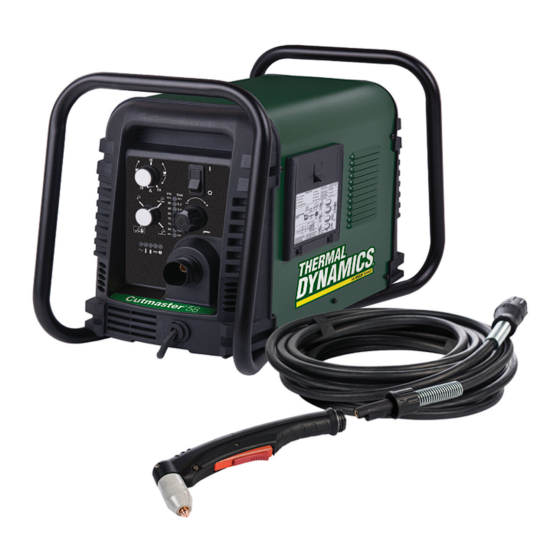
- Page 1 SL60QD OUTPUT MAX OUTPUT VOLTAGE VOLTAGE VOLTAGE 208- 460V 600V 460V INPUT POWER INPUT POWER CutMaster ® PLASMA CUTTING SYSTEM OPERATING MANUAL Art # A-13750_AB Revision: AA Issue Date: Manual No.: 0-5544 11-07-2018 esab.com...
- Page 2 WE APPRECIATE YOUR BUSINESS! Congratulations on your new Thermal Dynamics product. We are proud to have you as our customer and will strive to provide you with the best service and reliability in the industry. This product is backed by our extensive warranty and world-wide service network. To locate your nearest distributor or service agency call 1-800-426-1888, or visit us on the web at www.esab.com.
- Page 3 2800 Airport Rd. Denton, Texas 76207 www.esab.com © Copyright 2018 by Thermal Dynamics an ESAB brand. All rights reserved. Reproduction of this work, in whole or in part, without written permission of the publisher is prohibited. The publisher does not assume and hereby disclaims any liability to any party for any loss or damage caused by any error or omission in this Manual, whether such error results from negli- gence, accident, or any other cause.
- Page 4 Be sure this information reaches the operator. You can get extra copies through your supplier. CAUTION These INSTRUCTIONS are for experienced operators. If you are not fully familiar with the principles of operation and safe practices for arc welding and cutting equipment, we urge you to read our booklet, “Precautions and Safe Practices for Arc Welding, Cutting, and Gouging,”...
- Page 5 ASSUREZ-VOUS QUE CETTE INFORMATION EST DISTRIBUÉE À L’OPÉRATEUR. VOUS POUVEZ OBTENIR DES COPIES SUPPLÉMENTAIRES CHEZ VOTRE FOURNISSEUR. MISE EN GARDE Les INSTRUCTIONS suivantes sont destinées aux opérateurs qualifiés seulement. Si vous n’avez pas une connaissance approfondie des principes de fonctionnement et des règles de sécurité...
- Page 6 This Page Intentionally Blank...
-
Page 7: Table Of Contents
TABLE OF CONTENTS SECTION 1: GENERAL INFORMATION ................1-1 1.01 Notes, Cautions and Warnings ................ 1-1 SECTION 2 SYSTEM: INTRODUCTION ..................2-1 2.01 How To Use This Manual ................2-1 2.02 Equipment Identification ................. 2-1 2.03 Receipt Of Equipment ..................2-1 2.04 Power Supply Specifications ................ - Page 8 TABLE OF CONTENTS PATENT INFORMATION ................. 4T-14 SECTION 5 SYSTEM: SERVICE ....................5-1 5.01 General Maintenance ..................5-1 5.02 Maintenance Schedule ..................5-2 5.03 Common Faults ....................5-2 5.04 Fault Indicator ....................5-3 5.05 Basic Troubleshooting Guide ................5-4 5.06 Power Supply Basic Parts Replacement ............
-
Page 9: General Information
CUTMASTER 58 SECTION 1: GENERAL INFORMATION 1.01 Notes, Cautions and Warnings Throughout this manual, notes, cautions, and warnings are used to highlight important information. These high- lights are categorized as follows: NOTE! An operation, procedure, or background information which requires additional emphasis or is helpful in efficient opera- tion of the system. - Page 10 CUTMASTER 58 WARNING AVERTISSEMENT 1. Cutting sparks can cause explosion 1. Les étincelles de coupage peuvent or fire. provoquer une explosion ou un incendie. 1.1 Do not cut near flammables. 1.2 Have a fire extinguisher nearby and 1.1 Ne pas couper près des matières ready to use.
-
Page 11: Section 2 System
This Owner’s Manual applies to Thermal Dynamics® and ESAB on loosely attached card or the shipping container. Record CutMaster 58 systems these numbers on the bottom of page i for future reference. -
Page 12: Power Supply Specifications
20 - 60 Amps, Continuously Adjustable Power Supply Gas Particulates to 5 Microns Filtering Ability CutMaster 58 Power Supply Duty Cycle * Duty Cycle Ratings @ 40° C (104° F) Ambient Temperature Operating Range 0° - 50° C IEC Rating... -
Page 13: Input Wiring Specifications
CUTMASTER 58 2.05 Input Wiring Specifications CutMaster 58 Power Supply Input Cable Wiring Requirements Input voltage Freq Power Input Suggested Sizes Flexible Cord Volts I max Fuse (amps) (Min. AWG) 10.4 1 Phase 10.8 15.2 50/60 50/60 3 Phase 50/60... -
Page 14: Power Supply Features
CUTMASTER 58 2.06 Power Supply Features Handle and Leads Wrap Control Panel Torch Leads Receptacle Art # A-07942 Work Cable and Clamp Port for Optional Automation Interface Cable Input Power Selection Filter Assembly Gas Inlet Port Art # A-07981 Input Power Cord... -
Page 15: Section 2 Torch
CUTMASTER 58 SECTION 2 TORCH: 2T.03 Specifications INTRODUCTION A. Torch Configurations 1. Hand/Manual Torch, Model SL60QD™ 2T.01 Scope of Manual The hand torch head is at 75° to the torch handle. The hand torches include a torch handle and torch This manual contains descriptions, operating instructions trigger assembly. -
Page 16: 04 Quick Connection Torch
CUTMASTER 58 F. Torch Ratings 2T.04 Quick Connection Torch Manual Torch Ratings The new SL60QD™ (Quick Disconnect) torch allows Ambient 104° F for a quick change of the torch handle assembly from Temperature 40° C the leads. To change the torch handle assembly do the... - Page 17 CUTMASTER 58 D. Main Cutting Arc DC power is also used for the main cutting arc. The negative output is connected to the torch electrode through the torch lead. The positive output is con- nected to the workpiece via the work cable and to the torch through a pilot wire.
- Page 18 CUTMASTER 58 This Page Intentionally Blank INTRODUCTION Manual 0-5544 2T-4...
-
Page 19: Section 3 System
CUTMASTER 58 SECTION 3 SYSTEM: INSTALLATION 3.01 Unpacking 1. Use the packing lists to identify and account for each item. 2. Inspect each item for possible shipping damage. If damage is evident, contact your distributor and / or shipping company before proceeding with the installation. - Page 20 CUTMASTER 58 7. With a little slack in the wires, tighten the through NOTE! - hole protector to secure the power cable. There is only one jumper setting that changes between the single and three 8. Reinstall the Power Supply cover per instructions phase settings.
-
Page 21: Gas Connections
CUTMASTER 58 Installing Optional Single - Stage Air Filter 6. Connect the wires as follows. An optional filter kit is recommended for improved fil- • Set Jumper wires on the contactor. See previ- tering with compressed air, to keep moisture and debris ous illustrations.. - Page 22 CUTMASTER 58 Using High Pressure Air Cylinders Installing Optional Two - Stage Air Filter Kit When using high pressure air cylinders as the air supply: This optional two - stage air line filter is also for use on compressed air shop systems. Filter removes moisture 1.
-
Page 23: Section 3 Torch
CUTMASTER 58 SECTION 3 TORCH: 3. Place a welding filter lens in front of the torch and turn ON the air. Do not start an arc! INSTALLATION Any oil or moisture in the air will be visible on the lens. - Page 24 CUTMASTER 58 This Page Intentionally Blank INSTALLATION Manual 0-5544 3T-2...
-
Page 25: Section 4 System
CUTMASTER 58 SECTION 4 SYSTEM: OPERATION 4.01 Front Panel Controls / Features See Illustration for numbering Identification 1. Output Current Control Sets the desired output current. Output settings up to 60 Amps may be used for drag cutting (with the torch tip contacting the workpiece) or for standoff cutting. -
Page 26: Preparations For Operation
The area must be free from oil, paint and rust. Connect only to the main part of the workpiece; do not connect to the part to be cut off. Art# A-07946 STANDOFF CutMaster 58 Gas Pressure Settings Leads SL60QD SL100 Length... - Page 27 DRAG Refer to Section "4T.08 Recommended Cutting Speeds for Mechanized Torch With Exposed Tip" and following CutMaster 58 Gas Pressure Settings for greater details. SL60QD Leads Length Output current setting or cutting speeds may be re-...
- Page 28 CUTMASTER 58 This Page Intentionally Blank OPERATION Manual 0-5544...
-
Page 29: Section 4 Torch
CUTMASTER 58 SECTION 4 TORCH: 1. Unscrew and remove the shield cup assembly from the torch head. OPERATION 2. Remove the Electrode by pulling it straight out of the Torch Head. 4T.01 Torch Prts Selection Large O-Ring Small O-Ring Torch Head Depending on the type of operation to be done determines the torch parts to be used. -
Page 30: 03 General Cutting Information
CUTMASTER 58 Kerf Width 4T.03 General Cutting Information Cut Surface Bevel Angle WARNING Disconnect primary power at the source before dis- Spatter assembling the power supply, torch, or torch leads. Frequently review the Important Safety Precautions Top Edge at the front of this manual. Be sure the operator is... -
Page 31: 04 Hand Torch Operation
CUTMASTER 58 Left Side Cut Angle NOTE! Right Side The tip should never come in contact with the work- Cut Angle piece except during drag cutting operations. 2. Depending on the cutting operation, do one of the following: a. For edge starts, hold the torch perpendicular to... - Page 32 CUTMASTER 58 WARNING Trigger The straight edge must be non - conductive. Trigger Release Non-Conductive Straight Edge Cutting Guide A-03539 Using Drag Shield Cup With Straight Edge Art # A-03383 The crown shield cup functions best when cutting 3/16 6. Cut as usual. Simply release the trigger assembly to inch (4.7 mm) solid metal with relatively smooth...
- Page 33 CUTMASTER 58 Piercing With Hand Torch 1. The torch can be comfortably held in one hand or steadied with two hands. Position the hand to press the Trigger on the torch handle. With the hand Trigger torch, the hand may be positioned close to the torch head for maximum control or near the back end for maximum heat protection.
-
Page 34: 05 Gouging
CUTMASTER 58 7. Clean spatter and scale from the shield cup and the Optimum torch travel speed is dependent on current tip as soon as possible. Spraying the shield cup in setting, lead angle, and mode of operation (hand or anti - spatter compound will minimize the amount machine torch). -
Page 35: 06 Mechanized Torch Operation
CUTMASTER 58 For optimum smooth surface quality, the travel speed 4T.06 Mechanized Torch Operation should be adjusted so that only the leading edge of the arc column produces the cut. If the travel speed is too Cutting With Mechanized Torch... -
Page 36: 07 Parts Selection For Manual Torch Cutting
CUTMASTER 58 4T.07 Parts Selection for Manual Torch Cutting Art # A-13753 OPERATION Manual 0-5544 4T-8... -
Page 37: 08 Recommended Cutting Speeds For Mechanized Torch With Exposed Tip
CUTMASTER 58 4T.08 Recommended Cutting Speeds for Mechanized Torch With Exposed Tip Type Torch: SL60QDQD With Exposed Tip Type Material: Mild Steel Type Plasma Gas: Air Type Secondary Gas: Single Gas Torch Speed (Per Plasma Gas Pierce Thickness Output Amperage... - Page 38 CUTMASTER 58 Type Torch: SL60QD With Exposed Tip Type Material: Mild Steel Type Plasma Gas: Air Type Secondary Gas: Single Gas Torch Speed (Per Plasma Gas Pierce Thickness Output Amperage Standoff Flow (CFH) Pierce Minute) Press Height (Cat. Volts Delay...
-
Page 39: 09 Recommended Cutting Speeds For Mechanized Torch With Shielded Tip
CUTMASTER 58 Type Torch: SL60QD With Exposed Tip Type Material: Aluminum Type Plasma Gas: Air Type Secondary Gas: Single Gas Torch Speed (Per Plasma Gas Pierce Thickness Output Amperage Standoff Flow (CFH) Pierce Minute) Press Height (Cat. Volts Delay Inches... - Page 40 CUTMASTER 58 Type Torch: SL60QD With Shielded Tip Type Material: Stainless Steel Type Plasma Gas: Air Type Secondary Gas: Single Gas Torch Speed (Per Plasma Gas Pierce Thickness Output Amperage Standoff Flow (CFH) Pierce Minute) Press Height (Cat. Volts Delay...
- Page 41 CUTMASTER 58 Type Torch: SL60QD With Shielded Tip Type Material: Stainless Steel Type Plasma Gas: Air Type Secondary Gas: Single Gas Torch Speed (Per Plasma Gas Pierce Thickness Output Amperage Standoff Flow (CFH) Pierce Minute) Press Height (Cat. Volts Delay...
-
Page 42: Patent Information
CUTMASTER 58 PATENT INFORMATION Plasma Cutting Torch Patents The following parts are covered under U.S. and Foreign Patents as follows: Catalog # Description Patent(s) 9-8215 Electrode US Pat No(s) 6163008; 6987238 Other Pat(s) Pending 9-8213 Cartridge US Pat No(s) 6903301; 6717096; 6936786;... - Page 43 CUTMASTER 58 Catalog # Description Patent(s) 9-8245 Shield Cap US Pat No(s) 6914211; D496951 Other Pat(s) Pending The following parts are also licensed under U.S. Patent No. 5,120,930 and 5,132,512: Catalog # Description 9-8235 Shield Cap 9-8236 Shield Cap 9-8237...
- Page 44 CUTMASTER 58 OPERATION Manual 0-5544 4T-16...
-
Page 45: Section 5 System
CUTMASTER 58 SECTION 5 SYSTEM: SERVICE 5.01 General Maintenance Maintain more often Warning! if used under severe Disconnect input power before maintaining. conditions Each Use Visual check of torch tip and electrode Weekly Visually inspect the cables and leads. Replace as needed... -
Page 46: Maintenance Schedule
3. Metal too thick. 4. Worn torch parts Daily Operational Checks or Every Six Cutting 5. Cutting current too low. Hours: 6. Non - Genuine Thermal Dynamics parts used 1. Check torch consumable parts, replace if damaged or 7. Incorrect gas pressure worn. -
Page 47: Fault Indicator
CUTMASTER 58 5.04 Fault Indicator At initial power up, two lights will temporarily illuminate for 2-3 seconds to show the version of software used. To determine the first digit, count the function indicators left to right, 1 through 5. To determine the second digit count the pres- sure indicators, reading from bottom to top, 0 through 7. -
Page 48: Basic Troubleshooting Guide
CUTMASTER 58 5.05 Basic Troubleshooting Guide WARNING There are extremely dangerous voltage and power levels present inside this unit. Do not attempt to diagnose or repair unless you have had training in power electronics measurement and troubleshooting techniques. Problem - Symptom Possible Cause... - Page 49 CUTMASTER 58 Problem - Symptom Possible Cause Recommended Action FAULT & 80 PSI 1. Torch shield cup is loose. 1. Tighten shield cup by hand. Do not overtighten. indicators flashing. 2. Torch tip, electrode or starter 2. Turn OFF power supply. Remove shield cup. Install Gas flow is cycling cartridge missing.
-
Page 50: Power Supply Basic Parts Replacement
CUTMASTER 58 5.06 Power Supply Basic Parts C. Filter Element Assembly Replacement Replacement The Filter Element Assembly is in the rear panel. For better system performance, the filter element should be checked per the Maintenance Schedule (Section 5.02), and either cleaned WARNING or replaced. - Page 51 CUTMASTER 58 6. Disconnect the input line from the filter element as- Optional Single-Stage Filter Element sembly. Replacement 7. Remove the filter element assembly through the rear These instructions apply to power supplies where the optional opening. Single-Stage Filter has been installed.
- Page 52 CUTMASTER 58 Optional Two-Stage Filter Element Replacement The Two-Stage Air Filter has two Filter Elements. When the Filter Elements become dirty the Power Supply will continue to oper- ate but cut quality may become unacceptable. Refer to Section 6, Parts List, for replacement filter element catalog number.
-
Page 53: Section 5 Torch
CUTMASTER 58 SECTION 5 TORCH: SERVICE Upper Groove 5T.01 General Maintenance with Vent Holes Must Remain Open NOTE! Upper O-Ring Refer to Previous “Section 5: System” for common in Correct Groove and fault indicator descriptions. Threads Lower O-Ring Art # A-03725... -
Page 54: 02 Inspection And Replacement Of Consumable Torch Parts
CUTMASTER 58 5T.02 Inspection and Replacement of Good Tip Worn Tip Consumable Torch Parts WARNING Disconnect primary power to the system before disassembling the torch or torch leads. A-03406 DO NOT touch any internal torch parts while the AC Example of Tip Wear indicator light of the Power Supply is ON. -
Page 55: Parts Lists
The following items are included with the replacement power supply: work cable & clamp, input power cable, gas pressure regula- tor / filter, and operating manual. Description Catalog # CutMaster 58 Power Supply 208/230 - 460VAC, Single or 3 Phase, 60Hz, with input power cable and plug 3-5830-1... -
Page 56: Options And Accessories
CUTMASTER 58 NOTE! *9-0115 regulator, If the serial number of the power supply is prior to #05078755 then kit number 9-0201 will be needed to replace not only the regulator (9-0115) but the logic PCB as well. Another way to tell if the kit is needed is to see if the regulator has a small diameter tube coming out of the bottom fitting. -
Page 57: Replacement Parts For Hand Torch
CUTMASTER 58 6.06 Replacement Parts for Hand Torch Item # Description Catalog # Torch Handle Assembly Replacement 7-5680 Leads Assemblies with ATC connector and Quick Connectors SL60QD™, 20 - foot Leads Assembly with ATC and QD connectors 4-5604 SL60QD™, 50 - foot Leads Assembly with ATC and QD connectors 4-5605 1&2... -
Page 58: Torch Consumable Parts (Sl60)
CUTMASTER 58 6.07 Torch Consumable Parts (SL60) Art # A-13753 PARTS LIST Manual 0-5544... -
Page 59: Torch Consumable Parts (Sl100)
CUTMASTER 58 6.08 Torch Consumable Parts (SL100) 20-40A Shield Tip: Shield Cap, Machine Cup Body, STANDOFF 40A 9-8245 9-8237 CUTTING 9-8205 Shield Cap, Deflector Shield Cup 9-8206 9-8243 9-8218 9-8208 Drag Shield Cap 9-8235 50-60A Shield Tips: STANDOFF Cup Body,... - Page 60 CUTMASTER 58 This Page Intentionally Blank PARTS LIST Manual 0-5544...
-
Page 61: Appendix 1: Sequence Of Operation (Block Diagram
CUTMASTER 58 APPENDIX 1: SEQUENCE OF OPERATION (BLOCK DIAGRAM) ACTION: ACTION: ACTION: ACTION: RUN / Rapid Auto Restart / ON / OFF switch to ON Close external RUN / SET / LATCH disconnect switch. Rapid Auto Restart / switch to RUN... -
Page 62: Appendix 2: Data Tag Information
CUTMASTER 58 APPENDIX 2: DATA TAG INFORMATION West Lebanon, NH USA 03784 Manufacturer's Name and/or Logo, Location, Model and ® Revision Level, Serial Number M odel : and Production Code Dat e of M f r : Made in USA... -
Page 63: Appendix 3: Torch Pin - Out Diagrams
CUTMASTER 58 APPENDIX 3: TORCH PIN - OUT DIAGRAMS A. Hand Torch Pin - Out Diagram ATC Female Receptacle ATC Male Connector Front View Front View Negative / Negative / Plasma Plasma 8 - Open 8 - Open 4 - Green /... -
Page 64: Appendix 4: Torch Connection Diagrams
CUTMASTER 58 APPENDIX 4: TORCH CONNECTION DIAGRAMS A. Hand Torch Connection Diagram Torch: SL60 / SL100 Hand Torch Leads: Torch Leads with ATC Connector Power Supply: with ATC Receptacle Male ATC Leads ATC Female Power Connector Receptacle Torch Torch Supply... - Page 65 CUTMASTER 58 This Page Intentionally Blank Manual 0-5544 APPENDIX...
-
Page 66: Appendix 5: System Schematic, 208/460V Units
CUTMASTER 58 APPENDIX 5: SYSTEM SCHEMATIC, 208/460V UNITS K1-K4 K1-K4 K5, K6 K5, K6 PRI 2 PRI 2 PRI 1 PRI 1 PRI 4 PRI 4 PRI 3 PRI 3 +12VDC BIAS SUPPLY MTH2 MTH2 MTH1 MTH1 C1-C4* C1-C4* /INRUSH... - Page 67 05/09/08 Date: Date: Date: ECO B1159 10/03/08 Information Proprietary to THERMAL DYNAMICS CORPORATION. Information Proprietary to THERMAL DYNAMICS CORPORATION. Information Proprietary to THERMAL DYNAMICS CORPORATION. Thursday, March 27, 2008 Thursday, March 27, 2008 Thursday, March 27, 2008 Not For Release, Reproduction, or Distribution without Written Consent.
-
Page 68: Appendix 6: System Schematic, 600V Units
CUTMASTER 58 APPENDIX 6: SYSTEM SCHEMATIC, 600V UNITS PRI 1 PRI 1 PRI 2 PRI 2 PRI 4 PRI 4 PRI 3 PRI 3 BIAS SUPPLY MTH2 MTH2 MTH1 MTH1 +12VDC + C1-C4* + C1-C4* CHOKE /INRUSH CE UNITS ONLY... - Page 69 St Louis, MO 63017 USA St Louis, MO 63017 USA Date: Date: Date: Information Proprietary to THERMAL DYNAMICS CORPORATION. Information Proprietary to THERMAL DYNAMICS CORPORATION. Information Proprietary to THERMAL DYNAMICS CORPORATION. Thursday, March 27, 2008 Thursday, March 27, 2008 Thursday, March 27, 2008 Not For Release, Reproduction, or Distribution without Written Consent.
-
Page 70: Appendix 7: Publication History
CUTMASTER 58 APPENDIX 7: Publication History Cover Date Rev. Change(s) July 11, 2018 Manual released. APPENDIX Manual 0-5544 A-10... - Page 71 This Page Intentionally Blank...
- Page 72 THE AMERICAS Denton, TX USA U.S. Customer Care Ph 1-800-426-1888 (tollfree) Fax: 1-800-535-0557 (tollfree) International Customer Care Ph 1-940-381-1212 Fax: 1-940-483-8178 Miami, FL USA Sales Office, Latin America Ph 1-954-727-8371 Fax: 1-954-727-8376 Oakville, Ontario, Canada Canada Customer Care Ph 1-905-827-4515 Fax: 1-800-588-1714 (tollfree) U.S.
Need help?
Do you have a question about the CutMaster 58 and is the answer not in the manual?
Questions and answers
It flashing min when I turn it on
When the Thermal Dynamics CutMaster 58 flashes "MIN" along with the FAULT and GAS pressure indicators, it means one of the following:
1. The gas supply is not connected.
2. The gas supply is not turned ON.
3. The gas pressure is too low.
To fix this, connect the gas supply, turn it ON, and ensure the pressure is at the required level.
This answer is automatically generated