Table of Contents
Advertisement
Quick Links
https://wiki.teltonika-gps.com/view/FMC234_First_Start
FMC234 First Start
Main Page
>
Advanced Trackers
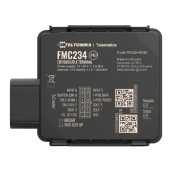
GNSS/GSM/Bluetooth tracker with internal GNSS/GSM antennas, internal battery and IP67
protection
400px
Contents
1 How to insert Micro-SIM card and connect battery
How to insert Micro-SIM card and connect battery
1.You will receive your device partly closed.
2.Gently remove top and bottom covers.
3.Insert SIM card as shown with PIN request disabled or read our Wiki how to enter it later in
Teltonika Configurator. Make sure that SIM card cut-off corner is pointing outward from slot. SIM
slot 1 is closer to PCB, SIM slot 2 is the top one.
4.Connect battery as shown to device. Position the battery in place where it does not obstruct other
components.
5.After configuration, see "PC Connection (Windows)", attach device top and bottom cover back and
press them twice to the full closure.
6.Make sure that product casing is closed correctly.
This device has an IP67 casing with a two-phase closing, that ensures a reliable protection and ease of use. Please make sure that
product casing corner clips are fixed tightly and cable is connected to the device in order to maintain the degree of IP67 protection.
>
FMC234
> FMC234 First Start
Advertisement
Table of Contents

Related Manuals for Teltonika FMC234


Summary of Contents for Teltonika FMC234
- Page 1 3.Insert SIM card as shown with PIN request disabled or read our Wiki how to enter it later in Teltonika Configurator. Make sure that SIM card cut-off corner is pointing outward from slot. SIM slot 1 is closer to PCB, SIM slot 2 is the top one.
- Page 2 Battery placement after complete device disassembling Using double sided tape, stick internal battery to the bottom part of the device case. Battery should be glued approximately 15 millimeters from the bottom wall of the case. Picture on the left. Connect battery to the PCB. Gently place PCB into the bottom case.
- Page 3 Data for 1–Wire devices. INPUT 5 RX EXT (LVCAN - RX). PC Connection (Windows) Power-up FMC234 with DC voltage 10-30 V power supply using supplied power cable. LED’s should start blinking, see “FMC234 LED status”. Connect device to computer using Micro-USB cable or Bluetooth connection:...
- Page 4 Maintenance and etc. FMC234 has one user editable profile, which can be loaded and saved to the device. After any modification of configuration the changes need to be saved to device using Save to device button. Main buttons offer following functionality: Load from device –...
- Page 5 1 hour passes while vehicle is stationary and ignition is off Records sending to server: If device has made a record it is sent to the server every 120 seconds After successful SMS configuration, FMC234 device will synchronize time and update records to...
- Page 6 Time intervals and default I/O elements can be changed by using Teltonika Configurator parameters. Mounting recommendations Connecting wires Wires should be connected while the module is not plugged in. Wires should be fastened to stable wires or other non-moving parts. Any heat emitting and/or moving objects should be kept away from the wires.
- Page 7 Device should be mounted with the sticker view to the open sky. 400px FMC234 device should be mounted with the device logo view to the open sky for the best device performance with not less than ¾ of metal free area. FMC234 has IP67 protection class. Top performance is reached if mounted outside of the vehicle.
- Page 8 The device must be firmly fastened in a predefined location. The programming must be performed using a PC with autonomic power supply. The device is susceptible to water and humidity. Installation and/or handling during a lightning storm is prohibited. https://teltonika.lt/product/FMC234/...
Need help?
Do you have a question about the FMC234 and is the answer not in the manual?
Questions and answers