Table of Contents
Advertisement
Quick Links
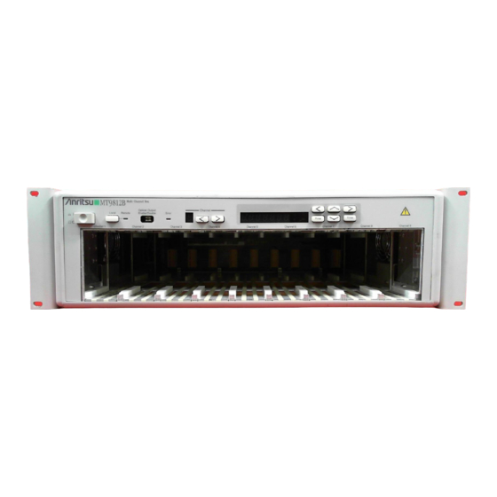
MT9812B
Multi Channel Box
Service Manual
Third Edition
Read this manual before using the equipment.
Keep this manual with the equipment.
This manual explains important service items
related to service. Read both the operation
manual and this manual, and keep both with
the equipment.
Measurement Solutions
ANRITSU CORPORATION
Document No.: M-W1555BE-3.0
Advertisement
Chapters
Table of Contents
Troubleshooting

Subscribe to Our Youtube Channel
Related Manuals for Anritsu MT9812B


Summary of Contents for Anritsu MT9812B
- Page 1 MT9812B Multi Channel Box Service Manual Third Edition Read this manual before using the equipment. Keep this manual with the equipment. This manual explains important service items related to service. Read both the operation manual and this manual, and keep both with the equipment.
- Page 2 Safety Symbols To prevent the risk of personal injury or loss related to equipment malfunction, Anritsu Corporation uses the following safety symbols to indicate safety-related information. Insure that you clearly understand the meanings of the symbols BEFORE using the equipment.
-
Page 3: For Safety
Always request repair by a trained engineer who understands the hazards. Anritsu Corporation will not accept liability for any injuries sustained as a result of opening the equipment covers. - Page 4 4. This equipment cannot be repaired by the user. DO NOT attempt to open the cabinet or to disassemble internal parts. Only Anritsu- trained service personnel or staff from your sales representative...
- Page 5 For Safety CAUTION 1. Before changing the fuses, ALWAYS remove the power cord from the poweroutlet and replace the blown fuses. ALWAYS use new fuses of the type and rating specified on the fuse marking on the Changing Fuse rear panel of the cabinet. CAUTION T___A indicates a time-lag fuse.
- Page 6 For Safety WARNING This equipment uses parts radiating Class 3 laser radiation. The warning labels shown on the next page are attached near the laser- radiation locations. The product name and the danger classification specified by JIS, IEC60825 and 21CFR1040.10 are explained below. Laser Radiation Markings Type JIS, IEC60825...
- Page 7 For Safety WARNING Class 1 Safe laser presenting no danger when used according to design specifications. Class 2 Laser radiating in 400 to 700 nm wavelength range. In principal, this class of laser is not safe, but the danger to the eyes is eliminated by the eye avoidance reaction in- cluding the blink response.
- Page 8 ANRITSU CORP. THIS PRODUCT CONFORMS TO 10-27 MINAMIAZABU 5-CHOME ALL APPLICABLE STANDARDS MINATO-KU, TOKYO, 106, JAPAN UNDER 21 CFR 1040.10 MANUFACTURED AT:ANRITSU CORP. ATSUGI PLANT. <IEC> <IEC> INVISIBLE LASER RADIATION DO NOT STARE INTO BEAM OR VIEW DIRECTLY WITH OPTICAL INSTRUMENTS...
- Page 9 Anritsu sales section or your near- est representative. Note: The battery used in this equipment has a maximum useful life of...
- Page 10 Notes On Export Management This product and its manuals may require an Export Li- cense/Approval by the Government of the product’s country of origin for re-export from your country. Before re-exporting the product or manuals, please contact us to confirm whether they are export-controlled items or not.
- Page 11 In addition, this warranty is valid only for the original equipment purchaser. It is not transferable if the equipment is resold. Anritsu Corporation will not accept liability for equipment faults due to unfore- seen and unusual circumstances, nor for faults due to mishandling by the cus- tomer.
-
Page 13: Table Of Contents
Table of Contents For Safety ............Section 1 General ......... 1.1 Introduction ..............1.2 Safety Precautions ............. Section 2 Mechanical Configuration ... 2.1 Introduction ..............2.2 Precautions ..............2.3 Mechanical Parts List ..........2.4 Cabinet Disassembly ..........Section 3 Troubleshooting ......3.1 Introduction .............. -
Page 15: Section 1 General
Section 1 General Introduction ............ Safety Precautions ........ -
Page 16: Introduction
Section 1 General 1.1 Introduction This service manual describes the repair of the MT9812B Multi Channel Box (MCB) and plug-in units. Section 2 describes how to disassemble and reassemble MCB, and the internal configuration. Section 3 describes how to troubleshoot and repair when a problem occurs during measurements or when abnormalities are detected during performance checks. -
Page 17: Section 2 Mechanical Configuration
Section 2 Mechanical Configuration Introduction ............ Precautions ............ Mechanical Parts List ........Cabinet Disassembly ........ -
Page 18: Introduction
Always follow the procedure steps below before disassembly and reassembly. Step Procedure Turn OFF the MT9812B power switch. Unplug the plug for the AC outlet. Remove the plug-in units from the MT9812B mainframe. 2.3 Mechanical Parts List Mechanical Parts List for Fig. 2-1 (Outer Cabinet) Parts No. Description QTY. - Page 19 2.3 Mechanical Parts List Mechanical Parts List for Fig. 2-2 (Inter Cabinet) Parts No. Description QTY. W33B11842 Front Panel W22B3158 Bottom Chassis W33B11770 Top Chassis W32B11604 Bracket for Fan W32B11604B Bracket for Fan W32B11605 Plate for Power Unit W42B31935 Bracket for Switch W4B32981 Plate (1) W4B32982...
-
Page 20: Cabinet Disassembly
Section 2 Mechanical Configuration 2.4 Cabinet Disassembly... - Page 21 2.4 Cabinet Disassembly Fig. 2-1 Outer Cabinet...
- Page 22 Section 2 Mechanical Configuration...
- Page 23 2.4 Cabinet Disassembly CONTROL (MM900003A) 17, 30 REAR PANEL (MM900006A) POWER UNIT (SEC200-5225) MOTHER BOARD (MM900004A) FRONT PANEL (MM900020A) 15, 24, 36, 37 16, 27, 28, 29 Fig. 2-2 Inter Cabinet...
- Page 24 Section 2 Mechanical Configuration...
- Page 25 2.4 Cabinet Disassembly...
- Page 26 Section 2 Mechanical Configuration 2-10...
-
Page 27: Section 3 Troubleshooting
Section 3 Troubleshooting Introduction ............ Recommended Test Equipment ....Block Diagram ..........Overall Troubleshooting ........ 3.4.1 Flowchart Symbols ......3.4.2 Troubleshooting ........Troubleshooting for Main Frame ....3-10 3.5.1 Introduction ......... 3-10 3.5.2 Exchangeable Module ......3-10 3.5.3 Circuit Diagram ........3-11 3.5.4 Troubleshooting and Repair .... -
Page 28: Introduction
Optical Wavelength/ Frequency: 187 to 500 THz MF9630A Frequency Counter ≤0.1pm Resolution: Optical Spectrum Wavelength: 650 to 1750 nm MS9710B ≤±0.3 nm Analyzer Accuracy: 3.3 Block Diagram Fig. 3-1 shows the block diagram of the MT9812B and it’s plug-in unit. - Page 29 3.3 Block Diagram Fig. 3-1 Block Diagram...
- Page 30 Section 3 Troubleshooting...
-
Page 31: Overall Troubleshooting
(5) GPIB control is disable. (6) Remote Interlock Connector/Optical Output Enable key is disabled. (7) Key on Optical Unit is disable. (8) MT9812B can not control Optical Unit. (9) Optical Unit performance is out-of-specification. (10) No signal from Analog Output. - Page 32 Section 3 Troubleshooting (1) LED indicators don't light. Repair MT9812B faulty (2) All 7-segment LEDs indicate "8". Repair MT9812B faulty (3) Keys on MT9812B are disable. Repair MT9812B faulty (4) RS-232C control is disable. Repair MT9812B faulty (5) GPIB control is disable.
- Page 33 Light Source unit faulty CAUTION Don’t attach or remove the Light Source while power is ON. (7) Key on Optical Unit is disable. Start Can the MT9812B control the Optical Unit ? Repair Replace this optical unit to other channel.
- Page 34 Section 3 Troubleshooting (8) MT9812B can not control Optical Unit. Start Is the key on Optical Unit enable ? Repair Replace this optical unit to other channel. Optical Unit faulty Does the same phenomenon occur ? Repair MT9812B faulty CAUTION Don’t attach or remove the optical unit while power is ON.
- Page 35 3.4 Overall Troubleshooting (10) No signal from Analog Output on Optical Sensor. Repair Optical Sensor faulty...
-
Page 36: Troubleshooting For Main Frame
This section describes brief explanation of exchangeable modules and procedure to decide faulty module. 3.5.2 Exchangeable Module MT9812B employs exchangeable module system for maintenance. Table 3-2 shows the list of exchangeable modules in MT9812B. Table 3-2 Exchangeable Modules in MT9812B Model Name... - Page 37 3.5 Troubleshooting for Main Frame Table 3-3 shows the explanation of check terminal on MM900003A. Table 3-3 Explanation of check terminal on MM900003A Name Explanation +5 V, +12 V Voltages of the power supply. 24.576 MHz Clock from CPU. 40 MHz Clock for GPIB interface.
-
Page 38: Circuit Diagram
Section 3 Troubleshooting 3.5.3 Circuit Diagram Fig. 3-2 shows overall circuit diagram of MT9812B Multi Channel Box. 3-12... - Page 39 3.5 Troubleshooting for Main Frame Fig. 3-2 Overall Circuit Diagram 3-13...
- Page 40 Section 3 Troubleshooting 3-14...
-
Page 41: Troubleshooting And Repair
3.5 Troubleshooting for Main Frame 3.5.4 Troubleshooting and Repair (1) LED indicators don't light. (2) All 7-segment LEDs indicate "8". (3) Keys are disabled. (4) RS-232C control is disabled. (5) GPIB control is disabled. (6) Remote Interlock Connector/Optical Output Enable key is disable. (1) LED indicators don't light. - Page 42 Section 3 Troubleshooting (2) All 7-segment LEDs indicate "8". Repair MM900003A PCB faulty (3) Keys are disabled. Start Repair Does remote control enable ? MM900003A PCB faulty Repair MM900020A PCB faulty 3-16...
- Page 43 3.5 Troubleshooting for Main Frame (4) RS-232C control is disabled. Start Is remote control Set remote control selected RS-232C ? RS-232C at Dip-SW. Are baud rate, Set the RS-232C parity bit or stop bit parameters at Dip-SW. set correct ? Is RS-232C cable Replace RS-232C Cable cross type ?
- Page 44 (5) GPIB control is disabled. Start Is remote control Set remote control selected GPIB ? GPIB. Is address of Set address correctly at MT9812B correct ? Dip-SW. Is other equipment Release other equipment connected to GPIB from GPIB. power off ? Repair...
- Page 45 3.5 Troubleshooting for Main Frame (6) Remote Interlock Connector/Optical Output Enable key is disabled. Start Set Remote Interlock Connector short and Repair Optical Output Enable key on. Check the MM900002A PCB voltage of check terminal LD. faulty Is the voltage +5V ? Repair Light Source unit faulty 3-19...
-
Page 46: Parts List
Section 3 Troubleshooting 3.5.5 Parts List 3-20... - Page 47 3.5 Troubleshooting for Main Frame 3-21...
- Page 48 Section 3 Troubleshooting 3-22.
- Page 49 MT9812B Multi Channel Box Service Manual Read this manual before using the equipment. Keep this manual with the equipment.
- Page 50 ANRITSU CORPORATION 5-10-27, Minamiazabu, Minato-ku, Tokyo 106-8570 Japan / Phone: 81-3-3446-1111 Document No.: M–W1555BE Printed in Japan...
Need help?
Do you have a question about the MT9812B and is the answer not in the manual?
Questions and answers