Table of Contents
Advertisement
Quick Links
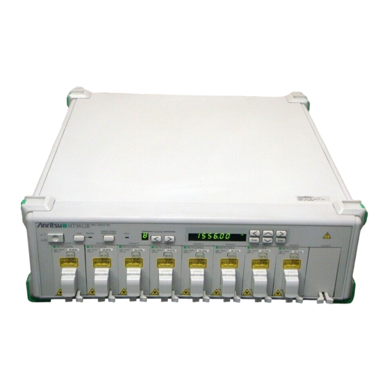
MT9810B
Optical Test Set
Service Manual
Second Edition
To ensure that the MT9810B Optical Test Set is
used safety, read the safety information in the
MT9810B Optical Test Set Manual first.
Keep this manual with the Optical Test Set.
Measurement Solutions
ANRITSU CORPORATION
Document No.: M-W1886BE-2.0
Advertisement
Chapters
Table of Contents
Troubleshooting

Subscribe to Our Youtube Channel
Related Manuals for Anritsu MT9810B


Summary of Contents for Anritsu MT9810B
- Page 1 MT9810B Optical Test Set Service Manual Second Edition To ensure that the MT9810B Optical Test Set is used safety, read the safety information in the MT9810B Optical Test Set Manual first. Keep this manual with the Optical Test Set. Measurement Solutions ANRITSU CORPORATION Document No.: M-W1886BE-2.0...
- Page 2 Safety Symbols To prevent the risk of personal injury or loss related to equipment malfunction, Anritsu Corporation uses the following safety symbols to indicate safety-related information. Insure that you clearly understand the meanings of the symbols BEFORE using the equipment.
-
Page 3: For Safety
Always request repair by a trained engineer who understands the hazards. Anritsu Corporation will not accept liability for any injuries sustained as a result of opening the equipment covers. - Page 4 For Safety WARNING This equipment uses parts radiating Class 2 or Class 3 laser radia- tion. The warning labels shown on the next page are attached near the laser-radiation locations. The product name and the danger classification specified by IEC60825-1 and 21CFR1040.10 are explained below. Laser Radiation Markings Type IEC60825-1...
- Page 5 For Safety WARNING Class 1 Safe laser presenting no danger when used according to design specifications. Class 2 Laser radiating in 400 to 700 nm wavelength range. In principal, this class of laser is not safe, but the danger to the eyes is eliminated by the eye avoidance reaction in- cluding the blink response.
- Page 6 ANRITSU CORP. THIS PRODUCT CONFORMS TO 10-27 MINAMIAZABU 5-CHOME ALL APPLICABLE STANDARDS MINATO-KU, TOKYO, 106, JAPAN UNDER 21 CFR 1040.10 MANUFACTURED AT:ANRITSU CORP. ATSUGI PLANT. y y y <IEC> <IEC> INVISIBLE LASER RADIATION DO NOT STARE INTO BEAM OR VIEW...
- Page 7 Notes On Export Management This product and its manuals may require an Export License/Approval by the Government of the product’s country of origin for re-export from your country. Before re-exporting the product or manuals, please contact us to confirm whether they are export-controlled items or not.
- Page 8 Power Line Fuse Protection For safety, Anritsu products have either one or two fuses in the AC power lines as requested by the customer when ordering. Single fuse: A fuse is inserted in one of the AC power lines. Double fuse: A fuse is inserted in each of the AC power lines.
- Page 9 This manual is written for service personnel trained by Anritsu Ser- vice Training Course and explains how to service the Anritsu MT9810B Optical Test Set, and how to troubleshoot faults. It also explains repair by exchanging modules but does not describe parts- level repair of modules.
-
Page 10: Table Of Contents
Table of Contents For Safety ............Section 1 General ......... 1.1 Introduction ..............1.2 Safety Precautions ............. 1.3 Components .............. Section 2 Mechanical Configuration ... 2.1 Introduction ..............2.2 Precautions ..............2.3 Mechanical Parts List ..........2.4 Cabinet Disassembly ..........Section 3 Troubleshooting ...... -
Page 11: Section 1 General
Section 1 General Introduction ..............Safety Precautions ............Components ..............1 - 1 1 - 1 1 - 1 1 - 1 1 - 1... -
Page 12: Introduction
General Introduction This service manual describes the repair of the MT9810B Optical Test Set (OTS) and plug-in units. Section 2 describes how to disassemble and reassemble OTS, and the internal configuration. Section 3 describes how to troubleshoot and repair when a problem occurs during measurements or when abnormalities are detected during performance checks. -
Page 13: Components
1 . 3 1 . 3 1 . 3 1 . 3 Components Components Components Components Components Components Name Model Remarks Main frame Optical Test Set MT9810B Plug-in unit Light Source MU952501A DFB-LD MU952502A DFB-LD MU952503A DFB-LD MU952504A DFB-LD MU952505A DFB-LD MU952601A... - Page 14 Section 1 Section 1 Section 1 Section 1 Section 1 General General General General General 1 - 4 1 - 4 1 - 4 ..1 - 4 1 - 4...
-
Page 15: Section 2 Mechanical Configuration
Section 2 Mechanical Configuration Introduction ..............Precautions ..............Mechanical Parts List ............. Cabinet Disassembly ............2 - 1 2 - 1 2 - 1 2 - 1 2 - 1... -
Page 16: Introduction
Mechanical Configuration Introduction This section describes the mechanical structure, the position of the internal units, and the procedure for removing these units to disassemble and reassemble the MT9810B. CAUTION Do not disassemble the plug-in unit. If the unit is broken, exchange it for new unit. -
Page 17: Mechanical Parts List
2 . 3 2 . 3 Mechanical Parts List Mechanical Parts List 2 . 3 2 . 3 2 . 3 Mechanical Parts List Mechanical Parts List Mechanical Parts List Mechanical Parts List Mechanical Parts List for Fig. 2-1 (Outer Cabinet) Parts No. - Page 18 Section 2 Section 2 Section 2 Mechanical Configuration Mechanical Configuration Mechanical Configuration Mechanical Configuration Section 2 Section 2 Mechanical Configuration Mechanical Parts List for Fig. 2-3 (Front Assembly) Parts No. Description Qty. W32H11704B Front frame W3E11622 Rubber switch W4H31492 Filter W4B31493 Dust-proof cushion W4B31501...
- Page 19 2 . 4 2 . 4 2 . 4 2 . 4 2 . 4 Cabinet Disassembly Cabinet Disassembly Cabinet Disassembly Cabinet Disassembly Cabinet Disassembly Fig. 2-1 Outer Cabinet 2 - 5 2 - 5 2 - 5 2 - 5 2 - 5...
- Page 20 2 - 6 2 - 6 2 - 6 2 - 6 2 - 6...
-
Page 21: Cabinet Disassembly
2 . 4 2 . 4 Cabinet Disassembly Cabinet Disassembly 2 . 4 2 . 4 Cabinet Disassembly 2 . 4 Cabinet Disassembly Cabinet Disassembly 2 - 7 2 - 7 2 - 7 2 - 7 2 - 7... - Page 22 Section 2 Section 2 Section 2 Section 2 Section 2 Mechanical Configuration Mechanical Configuration Mechanical Configuration Mechanical Configuration Mechanical Configuration 2 - 8 2 - 8 2 - 8 ..2 - 8 2 - 8...
-
Page 23: Section 3 Troubleshooting
Section 3 Troubleshooting Introduction ..............Recommended Test Equipment ........Block Diagram ..............Overall Troubleshooting ..........3.4.1 Flowchart symbols ..........3.4.2 Troubleshooting ........... Troubleshooting for Main frame ........3-21 3.5.1 Introduction ............3-21 3.5.2 Exchangeable module ......... 3-21 3.5.3 Circuit diagram ............ 3-22 3.5.4 Troubleshooting and repair ......... -
Page 24: Introduction
Wavelength: 650 to 1750 nm MS9710B ≤±0.3 nm Analyzer Accuracy: Block Diagram Fig. 3-1 shows the block diagram of the MT9810B and it's plug-in unit. 3 - 2 3 - 2 3 - 2 3 - 2 3 - 2... - Page 25 Fig. 3-1 Block Diagram 3 - 3 3 - 3 3 - 3 3 - 3 3 - 3...
- Page 26 3 - 4 3 - 4 3 - 4 3 - 4 3 - 4...
-
Page 27: Overall Troubleshooting
The flowcharts in the section 3 use the symbols shown below to explain the troubleshooting proce- dure. Work Check Repair Repair point and its contents NOTE: Explanations described below the figures inside the symbols are setting conditions for the MT9810B. 3 - 5 3 - 5 3 - 5 3 - 5 3 - 5... -
Page 28: Troubleshooting
(7) External Control is disable. (8) Remote Interlock Connector/Optical Output Enable key is disabled. (9) Key on Optical Unit is disable. (10) MT9810B can not control Optical Unit. (11) Optical Unit performance is out-of-specification. (12) No signal from Analog Output. - Page 29 Overall Troubleshooting 3 . 4 3 . 4 Overall Troubleshooting (4) RS-232C control is disable. Repair MT9810B faulty (5) GPIB control is disable. Repair MT9810B faulty (6) System memory backup is abnormal System memory is data setted by system key.
- Page 30 Replace Light Source another channel, Repair Repair MT9810B faulty Light Source unit faulty When replace Light Source, power off MT9810B. (9) Key on Optical Unit is disable. Start MT9810B control Optical Unit? Repair Replace Light Optical Unit faulty Source another...
- Page 31 3 . 4 3 . 4 3 . 4 3 . 4 Overall Troubleshooting Overall Troubleshooting Overall Troubleshooting Overall Troubleshooting Overall Troubleshooting (10) MT9810B can not control Optical Unit. Start Key on Optical Unit enable? Repair Replace Light Optical Unit faulty...
- Page 32 Section 3 Section 3 Section 3 Troubleshooting Troubleshooting Troubleshooting Troubleshooting Section 3 Section 3 Troubleshooting (13) Parameter memory backup is abnormal. Repair Optical Unit faulty (14) Trouble with Optical Sensors Zero Setting will Repair measured not complete, or Please contact the value is strange.
- Page 33 3 . 4 3 . 4 3 . 4 3 . 4 3 . 4 Overall Troubleshooting Overall Troubleshooting Overall Troubleshooting Overall Troubleshooting Overall Troubleshooting Is it long setting Repair for measurement Set the mode to suitable interval time? for your measurements. Is it narrow setting for measurement bandwidth?
- Page 34 Section 3 Section 3 Section 3 Troubleshooting Troubleshooting Troubleshooting Troubleshooting Section 3 Section 3 Troubleshooting Is the setting of Repair calibrated wavelength Set the mode to suitable different from the for your measurements. measuring beam? Is the end face of Repair the fiber cable or Clean the end of the fiber...
- Page 35 3 . 4 3 . 4 3 . 4 Overall Troubleshooting Overall Troubleshooting Overall Troubleshooting Overall Troubleshooting 3 . 4 3 . 4 Overall Troubleshooting (ii) Optical power is not stabilized. Is the ATT set at Repair 0.00 dB? Please set the ATT at 0.00 dB.
- Page 36 Please contact a near service center. (iv) Optical power does not out. Is the remote Repair interlock con- Please refer nector opened? MT9810B Operation Manual (3.5 Connection of Remote Interlock Connector). Is the optical Repair output modifier Please refer switch MT9810B Operation Manual turned off? (3.6...
- Page 37 3 . 4 3 . 4 3 . 4 Overall Troubleshooting Overall Troubleshooting Overall Troubleshooting Overall Troubleshooting 3 . 4 3 . 4 Overall Troubleshooting (v) Optical attenuation function does not operate. Repair The plug-in unit faulty. (vi) Optical frequency variable function does not operate. Repair The plug-in unit faulty.
- Page 38 Section 3 Section 3 Troubleshooting Troubleshooting Troubleshooting Troubleshooting Section 3 Section 3 Troubleshooting (16) MT9810B displays “NO UNIT” Turn OFF the MT9810B power switch. Replace the other plug-in unit, and turn ON the power switch. Repair Does The MT9810B faulty.
- Page 39 3 . 4 Overall Troubleshooting Overall Troubleshooting Overall Troubleshooting Overall Troubleshooting 3 . 4 3 . 4 Overall Troubleshooting (17) MT9810B displays “NO SENSOR” Turn OFF the MT9810B power switch. Replace the other Optical Sensor Head, and turn ON the power switch. Does...
- Page 40 (about 2 minutes). value is low. Please wait until the processing completes. Repair Turn OFF the MT9810B Please contact power switch. service center and ask Replace the other Optical the problem. Head and turn on the power switch.
- Page 41 Set the mode to suitable for measurement for your measurements. interval time? Is it narrow setting for measurement bandwidth? Turn OFF the MT9810B power switch. Replace the other Optical Head and turn on the power switch. Repair trouble Optical Head faulty...
- Page 42 Is the end face of Repair the fiber cable or Clean the end of the fiber connector cable and connector. stained? Turn OFF the MT9810B power switch. Replace the other Optical Head and turn on the power switch. Repair trouble...
-
Page 43: Troubleshooting For Main Frame
Introduction This section describes brief explanation of exchangeable modules and procedures to decide faulty module. 3.5.2 Exchangeable module MT9810B employs exchangeable module system for maintenance. Table 3-2 shows exchangeable modules in MT9810B. Table 3-2 Exchangeable Modules in MT9810B Model Name... -
Page 44: Circuit Diagram
Troubleshooting Section 3 Section 3 Troubleshooting 3.5.3 Circuit diagram Fig. 3-2 shows overall circuit diagram of MT9810B Optical Test Set. 3 - 2 2 3 - 2 2 3 - 2 2 3 - 2 2 3 - 2 2... - Page 45 Fig. 3-2 Circuit Diagram 3 - 2 3 3 - 2 3 3 - 2 3 3 - 2 3 3 - 2 3...
- Page 46 3 - 2 4 3 - 2 4 3 - 2 4 3 - 2 4 3 - 2 4...
-
Page 47: Troubleshooting And Repair
3 . 5 3 . 5 Troubleshooting for Main frame 3 . 5 Troubleshooting for Main frame Troubleshooting for Main frame Troubleshooting for Main frame 3 . 5 3 . 5 Troubleshooting for Main frame 3.5.4 Troubleshooting and repair (1) Display doesn’t light. (2) Initial Display doesn’t end. - Page 48 Section 3 Section 3 Troubleshooting Troubleshooting Section 3 Section 3 Section 3 Troubleshooting Troubleshooting Troubleshooting (2) Initial Display doesn’t end. Repair MM900078A faulty (3) Keys are disabled. Start Keys Repair disable? MM900078A PCB or MDA86AA or Rubber faulty Remote Control Repair enable? MM900078A...
- Page 49 3 . 5 3 . 5 3 . 5 Troubleshooting for Main frame 3 . 5 3 . 5 Troubleshooting for Main frame Troubleshooting for Main frame Troubleshooting for Main frame Troubleshooting for Main frame (4) RS-232C control is disabled. Start Remote Control is remote...
- Page 50 Troubleshooting Troubleshooting (5) GPIB control is disabled. Start Remote Control is Set remote control GPIB selected GPIB? Address of MT9810B Set Baud rate or parity is correct? bit or stop bit. Other equipment Release other equipment which is power off from GPIB.
- Page 51 3 . 5 3 . 5 3 . 5 Troubleshooting for Main frame 3 . 5 3 . 5 Troubleshooting for Main frame Troubleshooting for Main frame Troubleshooting for Main frame Troubleshooting for Main frame (7) Remote Interlock Connector/Optical Output Enable key is disabled. Start Check Voltage of LAND LD Remote Interlock Connector open or Optical Output...
- Page 52 Section 3 Section 3 Troubleshooting Troubleshooting Section 3 Section 3 Section 3 Troubleshooting Troubleshooting Troubleshooting (8) External Control is disabled. Start Observe TX terminal Repair on MM900078A with MM900078A PCB faulty oscilloscope. Signal generates? Observe pin of External control MM900079A with oscilloscope.
- Page 53 MT9810B Optical Test Set Service Manual Read this manual before using the equipment. Keep this manual with the equipment.
- Page 54 5-10-27, Minamiazabu, Minato-ku, Tokyo 106-8570 Japan / Phone: 81-3-3446-1111 ANRITSU CORPORATION Document No.: M–W1886BE Printed in Japan...
Need help?
Do you have a question about the MT9810B and is the answer not in the manual?
Questions and answers