Chapters
Table of Contents

Related Manuals for Anritsu MT9812B


Summary of Contents for Anritsu MT9812B
- Page 1 MT9812B Multi Channel Box Operation Manual Ninth Edition For safety and warning information, please read this manual before attempting to use the equipment. Keep this manual with the equipment. ANRITSU CORPORATION Document No.: M-W1555AE-9.0...
- Page 2 Ensure that you clearly understand the meanings of the symbols BEFORE using the equipment. Some or all of the following symbols may be used on all Anritsu equipment. In addition, there may be other labels attached to products that are not shown in the diagrams in this manual.
- Page 3 For Safety WARNING 1. ALWAYS refer to the operation manual when working near locations at which the alert mark shown on the left is attached. If the advice in the operation manual is not followed there is a risk of personal injury or reduced equipment performance.
- Page 4 Calibration 6. The performance-guarantee seal verifies the integrity of the equipment. To ensure the continued integrity of the equipment, only Anritsu service personnel, or service personnel of an Anritsu sales representative, should break this seal to repair or calibrate the equipment. If the performance-guarantee seal is broken by you or a third party, the performance of the equipment cannot be guaranteed.
- Page 5 For Safety CAUTION 1. Always remove the mains power cable from the power outlet before replacing blown fuses. There is a risk of electric shock if fuses are Fuse Replacement replaced with the power cable connected. Always use new fuses of the type and rating specified on the rear panel of the instrument.
- Page 6 For Safety Class 1, 1M indicate the danger degree of the laser radiation specified below according to IEC 60825-1:2001. Class 1: Lasers that are safe under reasonably foreseeable conditions of operation, including the use of optical instruments for intrabeam viewing. Class 1M: Lasers emitting in the wavelength range from 302.5 to 4000 nm that are safe under reasonably foreseeable conditions of operation, but may be hazardous if the user employs optics...
- Page 7 For Safety CAUTION Use of controls or adjustments or performance of procedures other than those specified herein may result in hazardous radiation exposure. The use of optical instruments with this product will increase eye hazard.
- Page 8 If this warning light does not turn on, the equipment may be faulty and for safety reasons should be returned to an Anritsu service center or representative for repair. The laser in the plug-in unit provided for this equipment is classified as Class 1, 1M according to the IEC 60825-1:2001 standard, or as Class I, IIIb according to the 21 CFR 1040.10:1995 standard.
- Page 9 For Safety Table 2 Laser Safety Classifications Based on FDA21 CFR 1040.10:1995 Max. Optical Pulse Width (s)/ Emitted Model Name Class Laser Aperture Output Power (mW) Repetition Rate Wavelength (nm) MU954501A Class I 1550 Fig. 1, [1] MU952501A Class IIIb 1545-1553 Fig.
- Page 10 Explanation Fig. 1, B MU951301A MU951501A MU951001A MU952501A/02A/03A/04A/05A MU952601A/02A/03A/04A/05A/06A Explanation Fig. 1, C MU951301A MU951501A MU951001A MT9810B Certification Fig. 1, D MT9812B MT9810B Identification Fig. 1, E MT9812B MU954501A MU952501A/02A/03A/04A/05A MU952601A/02A/03A/04A/05A/06A Warning Fig. 1, F MU951301A MU951501A MU951001A MU954501A MU952501A/02A/03A/04A/05A...
- Page 11 For Safety Laser Radiation Markings...
- Page 12 Back-up Battery the memory. This battery must be replaced by service personnel when it has reached the end of its useful life; contact the Anritsu sales section or your nearest representative. Note: The battery used in this equipment has a maximum useful life of 7 years.
- Page 13 In addition, this warranty is valid only for the original equipment purchaser. It is not transferable if the equipment is resold. Anritsu Corporation shall assume no liability for injury or financial loss of the customer due to the use of or a failure to be able to use this equipment.
- Page 14 Notes On Export Management This product and its manuals may require an Export License/Approval by the Government of the product's country of origin for re-export from your country. Before re-exporting the product or manuals, please contact us to confirm whether they are export-controlled items or not. When you dispose of export-controlled items, the products/manuals need to be broken/shredded so as not to be unlawfully used for military purpose.
- Page 15 2002/96/EC (the “WEEE Directive”) in European Union. For Products placed on the EU market after August 13, 2005, please contact your local Anritsu representative at the end of the product's useful life to arrange disposal in accordance with your initial contract and the local law.
- Page 16 CE Conformity Marking Anritsu affixes the CE conformity marking on the following product(s) in accordance with the Council Directive 93/68/EEC to indicate that they conform to the EMC and LVD directive of the European Union (EU). CE marking 1. Product Model...
- Page 17 4. Authorized representative Name: Loic Metais European Quality Manager ANRITSU S.A. France Address, city: 16/18 Avenue du Québec SILIC 720 Zone de Courtaboeuf 91951 Les Ulis Cedex Country: France xvii...
- Page 18 C-tick Conformity Marking Anritsu affixes the C-tick mark on the following product(s) in accordance with the regulation to indicate that they conform to the EMC framework of Australia/New Zealand. C-tick marking 1. Product Model Model: MT9812B Multi Channel Box 2. Applied Standards...
- Page 19 Power Line Fuse Protection For safety, Anritsu products have either one or two fuses in the AC power lines as requested by the customer when ordering. A fuse is inserted in one of the AC power lines. Single fuse: Double fuse: A fuse is inserted in each of the AC power lines.
- Page 21 About This Manual This manual provides descriptions of the operation, calibration and maintenance methods of the MT9812B Multi Channel Box. Section 4 outlines the basic func- tions and operations of MT9812B. By connecting to an external computer, this device can be remote-controlled.
- Page 22 Table of Contents For Safety ............About This Manual ........Section 1 General......... 1.1 MT9812B Multi Channel Box ........1.2 Plug-in Unit ..............1.3 Features ..............Section 2 Specifications......2.1 Component ..............2.2 Specifications ............. 2.3 Application Parts and Options ........
- Page 23 Section 5 Remote Control ......5.1 Settings ..............5.2 Specifications ............. 5.3 Device Message ............5.4 IEEE 488.2 Standard Status Model ......5-23 5.5 Status Byte Register ..........5-26 5.6 Enabling the SRQ ............5-30 5.7 Standard Event Status Register ........ 5-32 5.8 Queue Model .............
- Page 25 Section 1 General This section provides an outline of functions of the MT9812B Multi Channel Box and the plug-in unit, and explanations of the product features. MT9812B Multi Channel Box ......Plug-in Unit ............ Features ............
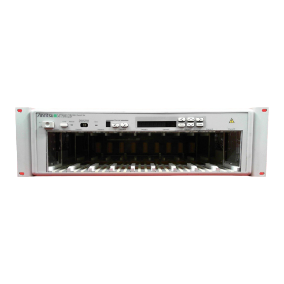
- Page 26 Section 1 General MT9812B Multi Channel Box The MT9812B Multi Channel box, that is one of the optical test set series, has slots in which up to nine plug-in units can be mounted. The MT9812B operates the unit mounted in each slot and displays the state of each unit and the measure- ment results.
- Page 27 1.2 Plug-in Unit Plug-in Unit The MT9812B enables mounting of the units shown below. MU952501A - MU952505A Light Source DFB-LD light source MU952601A - MU952606A Light Source DFB-LD light source MU951301A Light Source FP-LD light source MU951501A Light Source FP-LD light source...
- Page 28 Section 1 General Features (1) Mounting up to nine units The MT9812B enables to mount up to nine units for the MT9810A Optical Test Set. It is an appropriate light source to evaluate a multiplexed-wave- length optical communication system. (2) Compatible with wavelength conforming to ITU-T Provides a lineup of DFB-LD light sources of optical frequencies conform- ing to ITU-T compatible with Dense-WDM.
- Page 29 Section 2 Specifications Component ............ Specifications ..........Application Parts and Options .......
- Page 30 Section 2 Specifications Component Take the MT9812B Multi Channel Box out from the packing carton and check the articles provided with the component list. If any article is found missing or bro- ken, quickly contact ANRITSU or an ANRITSU dealer.
- Page 31 2.2 Specifications Specifications of Units (DFB-LD light sources) Model name MU952501A to MU952505A* Light emitting device DFB-LD Specified optical frequency (wavelength) range 191.7 to 195.9 THz (1563.86 to 1530.33 nm)* fp ±0.01 THz Center optical frequency* Spectrum half-amplitude level* 30 MHz (Max.) Conforming fiber SM fiber (ITU-T.G.
- Page 32 Section 2 Specifications Specifications of Units (DFB-LD light sources) Model name MU952601A to MU952606A* Light emitting device DFB-LD Specified optical frequency (wavelength) range fp 186.3 to 191.6 THz (1609.19 to 1564.68 nm)* fp ±0.01 THz Center optical frequency* Spectrum half-amplitude level* 30 MHz (Max.) Conforming fiber SM fiber (ITU-T.G.
- Page 33 2.2 Specifications Specifications of Units (FP-LD light sources) Model name MU951301A MU951501A MU951001A Light emitting device FP-LD 1310 ±20 nm 1550 ±20 nm 1310 ±20 nm/1550 ±20 nm Center frequency* ≤5 nm or less ≤10 nm or less ≤5 nm or less/≤10 nm or less Spectrum half-amplitude level* Conforming fiber SM fiber (ITU-T.G.
- Page 34 Section 2 Specifications (option 37) will be supplied as a standard feature. Specifications of Optical Sensors Model name MU931311A MU931421A Light receiving element InGaAs-PD Input system Fiber input Compatible with FC-PC, ST, DIN, HMS-10/A and SC ∗ Connector Wavelength range 800 to 1600 nm 750 to 1700 nm Optical power measurement range continuous light...
- Page 35 2.2 Specifications NOTE: *1: Measurement interval 1s, peak to peak *2: SM fiber (ITU-T.G.652) used. Reflection loss 45 dB (Min.) Wavelength 1550 nm *3: Reference conditions: SM fiber (ITU-T.G.652), master FC connector used Power level 100 µ W (–10 dBm), CW light, wave- length 1300 nm Ambient temperature: 23 ±2 °C On the day of calibration...
- Page 36 Section 2 Specifications Application Parts and Options Model name and code Item name Remarks –Application parts– J0006 GPIB cable 0.5 m J0007 GPIB cable 1 m J0008 GPIB cable 2 m J0009 GPIB cable 4 m J0655A RS-232C cable 9P-25P cross J0654A RS-232C cable 9P-9P cross –Main unit–...
- Page 37 2.3 Application Parts and Options Model name and code Item name Remarks –Option– (continued) MU952503A -08 Light source fp =191.80 THz MU952503A -09 Light source fp =191.90 THz MU952503A -10 Light source fp =192.00 THz MU952504A -01 Light source fp =194.10 THz MU952504A -02 Light source fp =194.20 THz...
-
Page 39: Table Of Contents
This section summarizes matters you are advised to learn before you start using the MT9812B. It is recommended that you read through this section at least once since this section provides descriptions of matters that require attention in order to ensure safety during the MT9812B use and avoid failures. -
Page 40: Installation
The installation environment condition of the MT9812B depends on the unit to be used. 2.2 Specifications It is advised not to use the MT9812B under environments such as the ones listed below as this may result in failure. • Places subject to vibrations •... -
Page 41: Power Source Voltage And Frequency
3.1.3 Power Source Voltage and Frequency Supply the MT9812B with power in the range between 85 and 132 Vac or between 170 and 250 Vac of voltage, and between 47.5 and 63 Hz of frequency. Although switching the setting between 100 and 200 V systems is not required. -
Page 42: Connecting The Power Cord
Section 3 Before Use Connecting the Power Cord Check that the power switch on the front panel is turned off. Insert the power plug into an outlet, and connect the other end to the power inlet on the rear panel. To ensure that the instrument is earthed, always use the sup- plied 3-pin power cord, and insert the plug into an outlet with a earth terminal. -
Page 43: Mounting And Removal Of Plug-In Unit
Mounting and Removal of Plug-in Unit Mounting (1) Check that the power source of the MT9812B is OFF. (2) Check the top and bottom of the unit and gently insert the unit along the guide rail of the plug-in slot. -
Page 44: Laser Safety
Section 3 Before Use Laser Safety The light source used by the MT9812B includes an element to radiate the laser light that corresponds to Class 1M in accordance with the IEC 60825-1 stipula- tions and Class III B in accordance with the FDA and 21 CFR stipulations. -
Page 45: Connection Of Remote Interlock Connector
(2) Remove the short plug affixed to the remote interlock connector. (Make sure not to lose the removed short plug.) (3) Connect the remote interlock connection plug that comes with the MT9812B and the switch as shown in the figure above, and affix the plug to the remote interlock connector. CAUTION... - Page 46 Section 3 Before Use POINT Polarity is not particularly specified in regard to con- nection to the remote interlock connector. The figure below shows the interior equivalent circuit. +5 V 10 kΩ Remote To the internal interlock circuit connector Unless the following three conditions are met, no opti- cal output will be made from the light source.
-
Page 47: Optical Output Modifier Key Switch
3.6 Optical Output Modifier Key Switch Optical Output Modifier Key Switch The MT9812B incorporates the optical output modifier key switch as one of the laser equipment safety devices to be used when the light source is used. Unless the switch with a removable key located at the back is ON, no light will be output even if the optical output key on the front panel of the unit is switched ON. -
Page 48: Connection Of Optical Fiber Cord
Section 3 Before Use Connection of Optical Fiber Cord Remove the cap (or open the cover) which is affixed to the optical connector on the front panel of the plug-in unit and connect the optical fiber cord. For Light Source unit Optical Optical fiber connector... -
Page 49: Replacement Of Optical Connector
3.8 Replacement of Optical Connector Replacement of Optical Connector The optical connector of the plug-in unit can be removed and replaced with a connector of another shape (optionally available), or its interior can be cleaned. Follow the procedures set out below to replace the optical connector. See 7.1 for the cleaning method. -
Page 50: Replacement Of Fuse
The MT9812B uses time lag type fuses of 5.0 A. Procedure for fuse replacement (1) The lower part of the AC inlet in the back of the MT9812B incorporates a fuse holder. Apply the tip of a minus driver or similar objects to the upper edge of the fuse holder. -
Page 51: 3.10 Others
Fuse holder 3.10 Others The electronic circuits and optical modules of the MT9812B and each plug-in unit are assembled and adjusted with precision. Disassembly or component re- placement to be conducted by the customer without due precaution may cause not only problems in maintaining the function but also operation failures. - Page 52 Section 3 Before Use 3-14.
- Page 53 Section 4 Operation Panel Description .......... 4.1.1 Front Panel ......... 4.1.2 Rear Panel ......... 4.1.3 Light Source Front Panel ....4.1.4 Light Sensor Front Panel ....Light Source Operation ........4.2.1 Switching Control Channels ....4.2.2 Optical Output ON/OFF ...... 4.2.3 Optical Output Enable/Disable (all light sources) ........
-
Page 54: Panel Description
(It is not possible to concurrently mount the blank panel and the unit.) 4 Control key When the MT9812B is in remote mode, the lamp on the right lights on. If this key is pressed in the remote mode, the mode returns to the local mode. In the local mode, the lamp goes off and the manual panel operation become enabled. -
Page 55: Rear Panel
3.9 Replacement of Fuse 14 Protective earth terminal A terminal to connect the ground line to ground the MT9812B to ensure safety. 15 Remote interlock connector A connector for laser safety. In the open status, no light will be output even when the light output switch on the front panel of the light source is turned ON. -
Page 56: Light Source Front Panel
Section 4 Operation POINT Although RS-232C is named EIA-232-E in accordance with the formal standards of ANSI/EIA, this document and descriptions relating to the MT9812B use the gen- eral name of RS-232C for explanations. 4.1.3 Light Source Front Panel MU952501A... - Page 57 4.1 Panel Description 4.1.4 Optical Sensor Front Panel MU931311A 1 Zero set key 2 Analog signal output connector 3 Optical connector 4 Drawing lever 5 Cap 1 Zero set key Used to remove the electrical offset of the light intercepting circuit. 4.3.2 Zero Set 2 Optical connector Connects the optical fiber cable to input measuring beam.
- Page 58 Section 4 Operation CAUTION The analog signal output connector is exclusively for output. When signals are input by mistake, this may cause damage to the Device or the signal source con- nected. Do not pull the cord while the cord remains inserted to the analog signal output connector.
-
Page 59: Light Source Operation
4.2 Light Source Operation Light Source Operation 4.2.1 Switching Control Channels Before setting the parameters on the MT9812B, selection of the unit to be set is performed, as described below. Operation Remarks Press the key. The selected channel is displayed on the num- ber indicator on the left. -
Page 60: Optical Output Enable/Disable
The pressing this key establishes the setting. One of the digits of the displayed output optical frequency (or wavelength) flick- ers. This implies that the MT9812B is now in the setting mode. The value of the flickering digit can be changed by pressing either the... - Page 61 4.2 Light Source Operation [When switchable light source is used.] (1) Switching of the output optical frequency Operations Remarks Press the Prmtr key. Continue pressing the key until the unit display turns to “THz” or “nm”. Press the key. The output optical frequency (or wavelength) is switched by each pressing the key.
-
Page 62: Setting Att
Section 4 Operation 4.2.5 Setting ATT The light source incorporates an attenuator function, which can be set in the range between 0.00 dB and 6.00 dB. The resolution is set at 0.01 dB. Operations Remarks Press the Prmtr key. Continue pressing the key until the unit display turns to “dB”... -
Page 63: Viewing Parameter
4.2 Light Source Operation 4.2.6 Viewing Parameter The details of the parameters set can be viewed (confirmed) without switching the mode to parameter setting. Operation Remarks Press the key. Pressing the key enables selection of the item to be viewed. Pressing the key causes the display to switch as follows. -
Page 64: Optical Sensor Operation
Section 4 Operation Optical Sensor Operation 4.3.1 Switching Control Channels Before setting the parameters on the MT9812B, select the unit to be controlled as described below. Operation Remarks Press the key. The selected channel is displayed on the num- ber indicator on the left. Press these keys until a desired channel appears. -
Page 65: Setting Calibration Wavelength (Optical Frequency)
“7.4 Troubleshooting.” 4.3.3 Setting Calibration Wavelength (Optical Frequency) As the photodetector of the optical sensor of the MT9812B has the wavelength sensitivity characteristics, the sensitivity compensation is required therefore to acquire the correct absolute measured value. Automatic compensation is carried out in the MT9812B when setting the wave- length (optical frequency) of the light to be measured. - Page 66 One of the digits of the displayed calibration wavelength flickers. This implies that the MT9812B is now in the setting mode. The value of the flickering digit can be changed by pressing either the ↑ or ↓ key, and the flickering digit (which can be inputted) can be changed by pressing either the ←...
-
Page 67: Reading Parameters
4.3 Optical Sensor Operation 4.3.4 Reading Parameters The parameter values can be confirmed without entering the parameter setting status. Operation Remarks Press either the key. Select the parameter item to be read. When pressing the key, the following parameters are sequentially displayed. Measurement value display (unit: dBm) →... - Page 68 Section 4 Operation 4-16.
- Page 69 5.3.2 Commands for Setting Light Source Unit ............. 5.3.3 Commands for Setting Optical Sensor Unit ............. 5-11 5.3.4 Commands for Setting MT9812B ..5-20 IEEE 488.2 Standard Status Model ....5-23 Status Byte Register ........5-26 5.5.1 ESB and MAV Summary Message ..5-26 5.5.2 Device Dependent Summary Message 5-27...
-
Page 70: Setting Gpib And Rs-232C
Section 5 Remote Control Settings 5.1.1 Setting GPIB and RS-232C Set the 8-pin DIP switches (Fig. 5-1) on the rear panel to use the GPIB or RS-232C. GPIB/RS-232C Fig. 5-1 (1) Using GPIB Pin 8: Set to 1. Pin 7: Not used. (Even if this pin is set to either 0 or 1, communication is not affected.) Pin 6: Not used. - Page 71 Fig. 5-3 RS-232C Setting Example RS-232C, 8 bits, no parity, stop bit: 2 bits, 9600 bps POINT The changed DIP switch setting becomes valid after the next power on. So, for using the MT9812B with the changed switch setting, turn the power on again.
-
Page 72: Specifications
Odd parity (ODD), even parity (EVEN), non- Parity parity (NON) Start bits 1 bit Stop bits 1 bit, 2 bits Connector D-sub 9-pin connector, female When the MT9812B is used with RS-232C, send the carriage return (CR) and the line feed (LF) after command. -
Page 73: Device Message
5.3 Device Message Device Message The following device messages are commands used commonly for both the GPIB and the RS-232C. The lowercase letters in the program messages can be omitted. 5.3.1 Commands for Setting Multiple Units The multiple-unit setting commands can specify the same set value for the mul- tiple units specified in <ch - list>. - Page 74 Section 5 Remote Control MFRame:POWer:STATe Function Sets optical output state. Program message MFRame:POWer:STATe < sw >, < ch - list > MFRame:POWer:STATe? < ch - list > Response message < sw > {, < sw >}∗ Parameter < sw > := {ON, OFF, 1, 0} <...
- Page 75 5.3 Device Message MFRame:POWer:WAVelength Function Sets optical frequency (wavelength). Program message MFRame:POWer:WAVelength < wavelength > [< unit >], < ch - list > MFRame:POWer:WAVelength? < ch - list > Response message < wavelength > {, < wavelength >}∗ Parameter < wavelength > := {f(m)|380 × 10 ≤...
-
Page 76: Commands For Setting Light Source Unit
Section 5 Remote Control 5.3.2 Commands for Setting Light Source Unit The light source unit setting commands specify various conditions for one light source unit specified in <n>. SOURce<n>:AM[:INTerval]:FREQuency Function Sets the modulation frequency. Program message SOURce<n>:AM[:INTerval]:FREQuency CW | < freq > [< unit >] SOURce<n>:AM[:INTerval]:FREQuency? Response message <... - Page 77 5.3 Device Message SOURce<n>:POWer:STATe Function Sets the optical power ON/OFF. Program message SOURce<n>:POWer:STATe < sw > SOURce<n>:POWer:STATe? Response message <status> Parameter < sw > := {ON, OFF, 1, 0} < status > := {1, 0} 1 ... ON 0 ... OFF Explanation This command turns optical power ON/OFF.
- Page 78 This command returns the measuring condition of the light source unit to the status at the shipment. POINT The MT9812B is not provided with the measuring-con- dition saving function, but units are initialized by the same message (reading out the contents in memory “0”) as that used in the Optical Test Set MT9810A.
-
Page 79: Commands For Setting Optical Sensor Unit
5.3 Device Message 5.3.3 Commands for Setting Optical Sensor Unit Using the optical sensor unit setting commands, the setting is made for the optical sensor unit specified by <n>. SENSe<n>:CORRection:COLLect:ZERO Function Executes offset. Program message SENSe<n>:CORRection:COLLect:ZERO SENSe<n>:CORRection:COLLect:ZERO? Response message < result > Parameter <... - Page 80 Section 5 Remote Control SENSe<n>:POWer:RANGe:AUTO Function Sets autorange. Program message SENSe<n>:POWer:RANGe:AUTO < sw > SENSe<n>:POWer:RANGe:AUTO? Response message < status > Parameter < sw > := {ON, OFF, 1, 0} < status > := {1, 0} Explanation Switches the measuring range between “AUTO range” and “MANUAL range.” Two modes are provided for the measuring range of the optical sensor;...
- Page 81 5.3 Device Message SENSe<n>:POWer:RANGe[:UPPer] Function Sets manual range. Program message SENSe<n>:POWer:RANGe[:UPPer] < level > [DBM] SENSe<n>:POWer:RANGe[:UPPer]? Response message < level > Parameter < level > := {30, 20, 10, 0, –10, –20, –30, –40, –50, –60, –70, –80, –90, –100, –110} Explanation This command executes measurements in the fixed <level>...
- Page 82 Section 5 Remote Control SENSe<n>:POWer:WAVelength Function Sets wavelength. Program message SENSe<n>:POWer:WAVelength < wavelength > [< unit >] SENSe<n>:POWer:WAVelength? Response message < wavelength > Parameter < wavelength > := {f(m)|380 × 10 ≤ f ≤ 1800 × 10 –9 –9 < wavelength > := {f(Hz)|166.551 × 10 ≤...
- Page 83 Switches the unit of the response to “FETCH<n>[:SCALar]:POWer[:DC]?.” POINT This command switches only the units of the response message. The unit display on the front panel of the MT9812B remains “dBm.” In addition, the unit of the response message to “MFRame:FETCh:POWer? <ch-list>” also remains “dBm.” 5-15...
- Page 84 This command switches whether or not the automatic setting of light-receive- circuit bandwidth is enabled. The MT9812B switches the measuring level range between “AUTO range” and “MANUAL range.” The measuring range of the optical sensor unit is provided with two modes; one is “AUTO range”...
- Page 85 5.3 Device Message SENSe<n>:BANDwidth Function Sets the bandwidth. Program message SENSe<n>:BANDwidth < bw > [< unit >] SENSe<n>:BANDwidth? Response message < bw > Parameter < bw > := {0.1, 1, 10, 100, 1000, 10000, 100000} (Unit: Hz) < unit > := {HZ, KHZ} Explanation This command sets the bandwidth to the value specified by <bw>.
- Page 86 × × –90 to –110 dBm HINT It is recommended that ordinarily the bandwidth set- ting be selected as “AUTO.” When using the MT9812B with an arbitrary specified fixed bandwidth, the mea- surement value can contain some error. SENSe<n>:FILTer:BPASs:FREQuency Function Sets the modulation frequency.
- Page 87 The <time> is set in units of seconds and rounded off by the resolution. POINT The MT9812B does not support the data read-out func- tion for a measuring interval of 100 ms or shorter. So, the measuring interval between 1 ms and 50 ms for the optical sensor unit can be set, but the measured value may not be read-out, correctly.
-
Page 88: Commands For Setting Mt9812B
Section 5 Remote Control 5.3.4 Commands for Setting MT9812B The setting MT9812B commands sets the necessary conditions of the MT9812B, separately from the unit settings, when using the remote control. SYSTem:ERRor Function Inquires the error value. Program message SYSTem:ERRor? Response message <... - Page 89 5.3 Device Message 2. Execution time error [-200 to -299] The error codes [-200 to -299] indicate the occurrence of errors in the execu- tion control unit of the device. If an error of this type occurs, bit 4 in the event status register is set.
- Page 90 Section 5 Remote Control SYStem:COMMunicate:GPIB:HEAD Function Sets the addition of header. Program message SYSTem:COMMunicate:GPIB:HEAD < flag > SYSTem:COMMunicate:GPIB:HEAD? Response message SYSTEM:COMMUNICATE:GPIB:HEAD < status > Parameter < flag > := {ON, OFF, 1, 0} < status > := {1, 0} 1 ... ON 0 ...
-
Page 91: Ieee 488.2 Standard Status Model
5.4 IEEE 488.2 Standard Status Model IEEE 488.2 Standard Status Model The diagram shown below is the standard model of the status data structure speci- fied by IEEE 488.2. & Power-ON (PON) & User request (URQ) & Command error (CME) ⋅... - Page 92 Section 5 Remote Control The status model uses an IEEE 488.1 status byte. This status byte consists of seven summary message bits provided by the status data structure. To generate these summary message bits, the status data structure is comprised of two models: a register model and a queue model.
- Page 93 5.4 IEEE 488.2 Standard Status Model (2) Status byte (STB) register and service request enable (SRE) reg- ister The status byte register consists of an RQS bit and seven summary message bits for setting status summary messages from the status data structure. It is used in combination with a service request enable register.
-
Page 94: Status Byte Register
Section 5 Remote Control Status Byte Register The status byte register consists of device STB and RQS (or MSS) messages. IEEE 488.1 defines the method of reporting STB and RQS messages, but it does not define the setting and clearing protocols and STB meaning. IEEE 488.2 de- fines device status summary messages and MSS transferred to bit 6 along with an STB in response to the ∗STB? common query. -
Page 95: Device Dependent Summary Message
5.5 Status Byte Registe 5.5.2 Device Dependent Summary Message IEEE 488.2 does not define whether status register bit 7 (DIO 8) and bit 3 (DIO 4) to bit 0 (DIO 1) are used as status register summary bits or the bits indicating existence of data in the queue. -
Page 96: Reading And Clearing The Status Byte Register
Section 5 Remote Control 5.5.3 Reading and Clearing the Status Byte Register Status byte register contents can be read using serial polling or an ∗STB? com- mon inquiry. IEEE 488.1 defined STB messages can be read by either method, but the value transferred to bit 6 (position) varies depending on the method. status byte register contents can be cleared using a ∗CLS command. - Page 97 5.5 Status Byte Registe (4) Clearing the status byte register using a ∗CLS common com- mand The ∗CLS common command clears all status structures, except the output queue and MAV summary message (i.e., event registers and queues), and the corresponding summary messages. Issuing a ∗CLS command after the <PROGRAM MESSAGE TERMINA- TOR>...
-
Page 98: Enabling The Srq
Section 5 Remote Control Enabling the SRQ Enabling the SRQ allows a summary message in the status byte register to be selected in response to a service request. The service request enable (SRE) regis- ter shown below can be used to select a summary message. Bits of the service request enable register correspond to the bits of the status byte (STB) register. - Page 99 5.6 Enabling the SRQ (3) Clearing the service request enable register The service request enable register can be cleared by executing an ∗SRE common command or turning on the power. When an ∗SRE common command is used, the service request enable regis- ter can be cleared by bringing the <DECIMAL NUMERIC PROGRAM DATA>...
-
Page 100: Standard Event Status Register
Section 5 Remote Control Standard Event Status Register 5.7.1 Definition of Standard Event Status Register Bits Any device conforming to IEEE 488.2 must have the standard event status regis- ter. Operation of the standard event register model is shown below, and the meaning of standard event status register bits given in IEEE 488.2 is explained in the Table 5-5. -
Page 101: Details On Query Errors
5.7 Standard Event Status Register 5.7.2 Details on Query Errors Table 5-6 Item Description When a device receives an MTA from the controller before receiving a program message terminator, it discards the incomplete message which has been received so far and waits for the next program mes- Incomplete program message sage. -
Page 102: Reading, Writing, And Clearing The Standard Event Status Register
Section 5 Remote Control 5.7.3 Reading, Writing, and Clearing the Standard Event Status Register Table 5-7 This register is read destructively in response to the ∗ESR? common command. In other words, Read this register is cleared after being read. The event bit assigned binary weights and converted to a decimal value <NR1>... -
Page 103: Queue Model
5.8 Queue Model Queue Model The right-hand side of the figure below shows a queue model having a status data structure. A queue is a data structure in which data is arranged sequentially, pro- viding information such as sequential status. A summary message indicates that such information exists in the queue. - Page 104 Section 5 Remote Control Table 5-9 Comparison of Output Queue to General Queues Item Output queue Queue Data input/output type FIFO type Not necessary to be FIFO type Response message units are read using only Response message units are read with an IEEE 488.2 message exchange protocol. device-dependent ...
-
Page 105: Ieee488.2 Common Commands
5.9 IEEE488.2 Common Commands IEEE488.2 Common Commands The following commands are used only for GPIB control. ∗CLS Function Clears the status. Program message ∗CLS Explanation The ∗CLS common command clears all event registers and queues except an out- put queue and its MAV summary messages, thus clearing the corresponding sum- mary messages. - Page 106 < manufacture >, < type >, < serial >, < farmware > Explanation This command displays the manufacturer name, model number, manufacture se- rial number, and firmware version, as follows. Manufacture name: ANRITSU Model no.: MT9812B Manufacture serial number: 0 Firmware version: 5-38...
- Page 107 When the device operation is completed, the bit 0 of the standard event status register is set. Then, “1” is set in the output queue, and an MAV summary mes- sage is generated. However, the MT9812B does not have any overlap command, therefore, this command has no meaning.
- Page 108 Section 5 Remote Control Explanation The total of values (2 = 1, 2 = 2, 2 = 4, 2 = 8, 2 = 16, 2 = 32, and/or 2 = 128) corresponding to the service request enable register bits 1, 2, 3, 4, 5, 6, and/or 7 that are enabled becomes parameter.
- Page 109 This command executes overlap commands as sequential commands. If this command is executed after an overlap command, the next command must wait for the current command to end. However, since the MT9812B does not have overlap commands, this command counts for nothing. 5-41...
-
Page 110: 5.10 Status Commands
Section 5 Remote Control 5.10 Status Commands This paragraph explains the device status report and the data structure defined by the IEEE488.2 standards. Each status register has the following configuration. (1) CONDITION REGISTER The condition register remains unchanged even after reading from the exter- nal device (controller). -
Page 111: 5.10.1 Status Register
5.10 Status Commands 5.10.1 Status Register STATus:PRESet Function Initializes the enable register and transition filters. Program message STATus:PRESet Explanation This command initializes the enable register and transition filters. Each register is set as shown in the table below. Register Filter/Enable Preset Value Enable all 0... - Page 112 Section 5 Remote Control < node >:ENABle Function Sets the event enable register. Program message < node >:ENABle < mask > < node >:ENABle? Parameter |0 ≤ n ≤ 15} < code > := {Logical sum of 2 Explanation This command finds the sum total of the bit digit values when the bit to be en- abled in the event enable register becomes the parameter.
- Page 113 5.10 Status Commands < node >:NTRansition Function Sets the N-transition register. Program message < node >:NTRansition < mask > < node >:NTRansition? Response message < mask > Parameter |0 ≤ n ≤ 15} < mask > := {Logical sum of 2 Explanation This command finds the sum total of the bit digit values when the bit to be en- abled in the N-transition register becomes the parameter.
-
Page 114: 5.10.2 Operation Status Register
Section 5 Remote Control 5.10.2 Operation Status Register The operation status register indicates the state of the equipment. The commands are shown below. Insert these commands into the <node> portion in the status register. Command Description STATus:OPERATION Operation status register STATus:OPERATION:SETTLING State of temperature of light source unit... -
Page 115: 5.10.3 Questionable Status Register
5.10 Status Commands 5.10.3 QUESTIONABLE Status Register QUESTIONABLE status register has the following information. • Output power of light source • Abnormalities of current/temperature/power-supply The QUESTIONABLE status register has the following commands, which are inserted into the <node> field of the status register for use. Command Description STATus:QUESTIONABLE:POWER... - Page 116 Section 5 Remote Control Explanation This command indicates the output ON/OFF state of light source. Each bit corresponds to a channel in sequence, assuming the bit 0 to be the chan- nel 1. This state indicates whether the optical output of the light source unit is on or off.
- Page 117 5.10 Status Commands STATus:QUEStionable:POWer:ENVTemp Function Indicates the temperature abnormality. Explanation This command indicates the occurrence of temperature abnormality. The bits correspond one for one with the channels in order with bit 0 as Channel 1. Depending on the state, whether temperature abnormality is occurring is indicated. Corresponding channel Channel 1 Channel 2...
- Page 118 Section 5 Remote Control 5-50.
- Page 119 Section 6 Performance Test This section provides explanations of the method to check the performance of the light source inserted to the MT9812B as well as the method to calibrate the mea- sured values. When the light source tested here is found to fail to meet specifications given here...
- Page 120 Section 6 Performance Test Light Source Performance Test Perform tests on two items shown below to check the performance of the light source. • Optical output level • Center optical frequency Clean the optical connector before starting the test. 7.1 Daily Care and Cleaning Perform the performance test after a sufficient time for warming up following power on.
- Page 121 6.1 Light Source Performance Test 6.1.1 Optical Output Level Optical fiber Measuring instrument tested Optical power meter Fig. 6-1 Step Operation Set up a measurement system like that shown in the figure, above. Set the optical output mode of the measuring instrument to be tested to the CW mode, and set ATT at 0 dB.
- Page 122 Section 6 Performance Test Optical Sensor Performance Test Perform tests on two items shown below to check the performance of the light sensor. • Linearity Between Ranges • Polarization Dependency • Return Loss • Noise Level Clean the optical connector before starting the test. 7.1 Daily Care and Cleaning Perform the performance test after a sufficient time for warming up following power on.
- Page 123 6.2 Optical Sensor Performance Test 6.2.1 Linearity Between Ranges Optical fiber Optical fiber Light source Variable optical attenuator Device under test (DUT) MN9625A × 2 MU952501A Fig. 6-3 Step Operation Set up a measurement system like that shown in figure, above. Insulate the DUT from the light for performing the zero-level calibration.
- Page 124 Section 6 Performance Test 6.2.3 Return Loss Device Under Test (DUT) Optical isolator Optical directional Light source coupler MN9604C Total-reflection MU952501A optical fiber Optical sensor and Power meter Fig. 6-5 Step Operation Set up a measurement system like that shown in figure, above. Input the light of about –20 dBm with the total-reflection opti- cal fiber attached to the measuring system.
- Page 125 Section 7 Maintenance and Re-transportation This section provides descriptions of matters that require attention in regard to daily care and cleaning and re-transportation and actions to be taken in the event of abnormalities. Daily Care and Cleaning ........ 7.1.1 External Stains ........7.1.2 Optical connector &...
-
Page 126: Daily Care And Cleaning
When external stains have grown conspicuous, when the MT9812B was used in dusty location or before the MT9812B is put to storage for a long time; lightly wipe the MT9812B to remove stains with a cloth soaked with soapy water. Using thinner or benzene may cause damage to the coating. - Page 127 7.1 Daily Care and Cleaning (2) Pull the adapter lever up then gently pull the adapter out straight towards you after checking that the latch is released. Adapter Lever Latch (3) Clean by pressing the adapter cleaner which is soaked in alcohol to the fer- rule end-face and side face.
- Page 128 Section 7 Maintenance and Re-transportation (4) Finish by pressing the tip of a new adapter cleaner without any alcohol on it to the ferrule end-face and wipe in one direction 2 or 3 times. (5) Clean the adapter interior with adapter cleaner. (Refer to “Cleaning optical adapter”...
- Page 129 7.1 Daily Care and Cleaning Cleaning the ferrule end-face of the fiber-optic cable Use ferrule cleaner supplies for this device to clean the ferrule of the cable end. An example of the FC connector is described below. Follow similar methods and steps for cleaning other connectors.
-
Page 130: Matters Requiring Attention For Storage
Section 7 Maintenance and Re-transportation Matters Requiring Attention for Storage Avoid storing the MT9812B and the plug-in units in places such as those listed below. • Places that experience temperatures of 70 ˚C or higher and of –20 ˚C or lower. -
Page 131: Re-Transportation
10 and 15 cm thick at the bottom of the box. (4) Put the MT9812B or the plug-in unit packed in sheet into the box and fill cushioning material around it. -
Page 132: Troubleshooting
Section 7 Maintenance and Re-transportation Troubleshooting 7.4.1 Common Items Phenomenon Possible cause Action Power is not activated. The power switch is not properly Press the power switch properly. pressed. The AC power source inlet and Connect the AC power source power source cord are not properly inlet, power source cord and power connected, or the power source... -
Page 133: Light Source
7.4 Troubleshooting 7.4.2 Light Source Phenomenon Possible cause Action The output power is low. The mode is set to ATT. Set the ATT to 0.00 dB. The end face of the fiber cord or Clean the end face of the fiber cord the connector is stained. -
Page 134: Optical Sensor
Section 7 Maintenance and Re-transportation 7.4.3 Optical Sensor Phenomenon Possible cause Action The measured value is low. The settings of the measuring beam Set the setting of the calibrated wave and calibrated wavelength are length to that of the wavelength of different. - Page 135 Appendix Appendix A Performance Test Result Recording List ........Appendix B Error Code ........App-i...
- Page 136 Appendix App-ii.
- Page 137 Appendix A Performance Test Result Recording List Appendix A Performance Test Result Recording List Light Source (DFB-LD) List of Performance Test Result Record Model: MU95250 Date: °C Serial No.: Temperature: Humidity: Atmospheric pressure: Person in charge: 1. Center Frequency Minimum∗ Reading Maximum∗...
- Page 138 Appendix A Performance Test Result Recording List Light Source (DFB-LD) List of Performance Test Result Record Model: MU95260 Date: °C Serial No.: Temperature: Humidity: Atmospheric pressure: Person in charge: 1. Center Frequency Minimum∗ Reading Maximum∗ THz ≤ THz ≤ ∗Minimum,Maximum: Select the appropriate one from the table below and enter it. Model Name Minimum Maximum...
- Page 139 Appendix A Performance Test Result Recording List Light Source (FP-LD) List of Performance Test Result Record Model: MU95 Date: °C Serial No.: Temperature: Humidity: Atmospheric pressure: Person in charge: 1. Center Wavelength Minimum Reading Maximum ≤ ≤ 1290 mn 1330 nm [1310 nm] ≤...
- Page 140 Appendix A Performance Test Result Recording List Optical Sensor List of Performance Test Result Record Model: MU931311A Date: °C Serial No.: Temperature: Humidity: Atmospheric pressure: Person in charge: 1. Linearity Test Range Power1 (dBm) Power2 (dBm) Power1–Power2 (dB) +10 dBm 0 dBm –...
- Page 141 Appendix A Performance Test Result Recording List Optical Sensor List of Performance Test Result Record Model: MU931421A Date: °C Serial No.: Temperature: Humidity: Atmospheric pressure: Person in charge: 1. Linearity Test Range Power1 (dBm) Power2 (dBm) Power1–Power2 (dB) +10 dBm 0 dBm –...
- Page 142 Appendix A Performance Test Result Recording List A-6.
- Page 143 Appendix B Error Code When an error occurs in the MT9812B or a inserted unit in the MT9812B, the code corresponding to the error is displayed in the parameter field. The error codes and causes are described below. E-001 An error occurred in mainframe memory.
- Page 144 Appendix B Error Code B-2.
Need help?
Do you have a question about the MT9812B and is the answer not in the manual?
Questions and answers