
Related Manuals for Lenze ERBG023D05K6


Summary of Contents for Lenze ERBG023D05K6
- Page 1 EDKRBG018R L−force Drives .@RI Mounting Instructions ERBGxxxxxxxx Brake resistor...
- Page 2 Please read these instructions and the documentation of the standard device before you start working! Observe the safety instructions given therein!
-
Page 3: Table Of Contents
Contents About this documentation ......... . Validity information . -
Page 4: About This Documentation
Qualified skilled personnel are persons who have the required qualifications to carry out all activities involved in installing, mounting, commissioning, and operating the product. Tip! Information and auxiliary devices around the Lenze products can be found in the download area at http://www.Lenze.com Document history... -
Page 5: Conventions Used
About this documentation Conventions used Conventions used Type of information Identification Examples/notes Spelling of numbers Decimal separator Point In general, the decimal point is used. For instance: 1234.56 Warnings UL warnings Are only given in English. UR warnings Text Program name »... -
Page 6: Notes Used
About this documentation Notes used Notes used The following pictographs and signal words are used in this documentation to indicate dangers and important information: Safety instructions Structure of safety instructions: Danger! (characterises the type and severity of danger) Note (describes the danger and gives information about how to prevent dangerous situations) Pictograph and signal word Meaning... - Page 7 About this documentation Notes used Special safety instructions and application notes for UL and UR Pictograph and signal word Meaning Safety or application note for the operation of a UL−approved device in UL−approved systems. Warnings! Possibly the drive system is not operated in compliance with UL if the corresponding measures are not taken.
-
Page 8: Safety Instructions
The manufacturer does not accept any liability for the suitability of the specified procedures and circuit proposals. Only qualified skilled personnel are permitted to work with or on Lenze ƒ drive and automation components. -
Page 9: Residual Hazards
Safety instructions Residual hazards Residual hazards Danger! Dangerous electrical voltage The terminals of the brake resistor may carry dangerous voltages during operation of the basic device and up to three minutes after mains disconnection. Possible consequences: Death or severe injuries when touching the terminals. ƒ... - Page 10 Safety instructions Residual hazards Stop! Possible overheating of the brake resistor during operation Inadequate heat dissipation during operation can cause the brake resistor to overheat. Possible consequences: The brake resistor is destroyed. ƒ The drive is not braked but coasts to a standstill. ƒ...
- Page 11 Safety instructions Residual hazards Warnings! Conditions of Acceptability: The product covered by this report is intended for use with Power ƒ Conversion Equipment and the like. The devices were tested for horizontal mounting positions. If ƒ other mounting positions are necessary in the end use applications, a temperature test shall be performed to ensure the maximum allowed temperature rise.
-
Page 12: Product Description
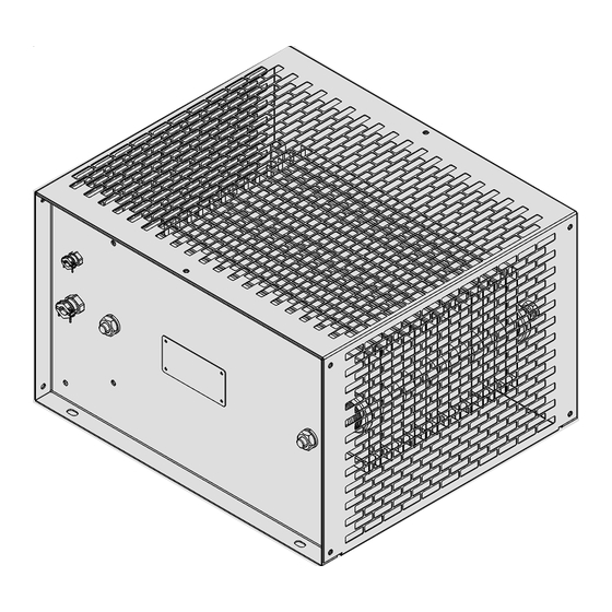
Product description Overview Product description Overview ERBG001 Scope of supply Pos. Description Brake resistor Mounting Instructions Brake resistor elements Pos. Description Nameplate Cable gland for brake resistor cable Cable gland for thermal contact cable EDKRBG018R DE/EN/FR/ES/IT 7.0... -
Page 13: Identification
Product description Identification Identification Lenze Type ERBG002 Type code ERBx xxxx xxxx Product series Resistance R 470R = 470 W e.g. 075D = 7.5 W Permanent power P e.g. 120W = 120 W 01k2 = 1.2 kW EDKRBG018R DE/EN/FR/ES/IT 7.0... -
Page 14: Application As Directed
Product description Application as directed Application as directed Brake resistors must only be actuated under the operating conditions specified in these ƒ operating instructions. are components ƒ – for mounting in a machine. – for assembly with other components to a machine. Commissioning of the brake resistor is prohibited until it has been determined that the machine into which the brake resistor is to be mounted complies with the regulations of the EC Machinery Directive. -
Page 15: Dimensioning Conditions
Product description Dimensioning conditions Dimensioning conditions If brake resistors are used, observe the following: Mean value of regenerative power < permanent power P of the brake ƒ resistor. Regenerative power during braking time < heat quantity Q of the brake ƒ... - Page 16 Product description Dimensioning conditions Examples of the evaluation of the condition The brake resistor cycle t = 150 s and the max. total braking time t cyc,RB brk,max = 10 s are given. The braking times t and the process cycle t cyc,Prc exemplary.
-
Page 17: Technical Data
Technical data General data and operating conditions Technical data General data and operating conditions Conformity and approval Conformity 2006/95/EC Low−Voltage Directive Approval UL508 Industrial Control Equipment, Underwriter Laboratories (File−No. E221095) for USA and Canada Protection of persons and equipment Enclosure EN 60529 IP20 NEMA 250... - Page 18 Technical data General data and operating conditions Mounting conditions Mounting location The mounting location must comply with the device features mentioned in the chapter "General data". Flammable materials or substances may not be placed in the vicinity of the brake resistor. The heat generated by the brake resistor must be dissipated freely.
-
Page 19: Rated Data
Technical data Rated data Rated data Electrical data [kWs] ERBG023D05K6 5600 ERBG028D04K1 4100 ERBG035D03K3 3300 ERBG043D03K0 3000 ERBG005R02K6 2600 ERBG075D01K9 1900 1000 ERBG012R01K9 12.0 ERBG012R05K2 5200 ERBG015R03K3 3300 ERBG015R06K2 6200 15.0 ERBG015R10K0 10000 1500 ERBG018R04K3 18.0 4300 Resistance Permanent power Heat quantity Max. -
Page 20: Mechanical Data
Technical data Mechanical data Mechanical data ERBG003 [mm] [kg] ERBG023D05K6 15.9 ERBG028D04K1 12.8 ERBG035D03K3 12.6 ERBG043D03K0 11.8 ERBG005R02K6 11.0 ERBG075D01K9 ERBG012R01K9 ERBG012R05K2 15.1 ERBG015R03K3 12.6 ERBG015R06K2 17.0 ERBG015R10K0 22.0 ERBG018R04K3 13.5 EDKRBG018R DE/EN/FR/ES/IT 7.0... - Page 21 Technical data Mechanical data Free spaces for standard mounting ERBG005 All dimensions in millimetres. Free spaces for mounting variant ERBG006 All dimensions in millimetres. EDKRBG018R DE/EN/FR/ES/IT 7.0...
-
Page 22: Mechanical Installation
Mechanical installation Mounting steps Mechanical installation Mounting steps How to mount the brake resistor: 1. Select a suitable mounting location. – The mounting location must always ensure the operating conditions mentioned in the technical data; if required, additional measures must be taken. -
Page 23: Electrical Installation
(thermal Tunnel terminal 18 ... 16 AWG 2.85 lb−in contact) ERBG023D05K6, ERBG028D04K1 Tip! The brake resistor has two PE connections, one inside, the other outside the housing. If you use a brake resistor cable with PE conductor, lead this ƒ... -
Page 24: Connection Plan
Electrical installation Connection plan Connection plan Version 1 (short cables) RB1 RB2 T1 T2 ERBG008 Twisted cables Version 2 (long cables) RB1 RB2 T1 T2 ERBG007 HF−shield termination by extensive PE connection Twisted cables EDKRBG018R DE/EN/FR/ES/IT 7.0... -
Page 25: Mounting Steps
Electrical installation Mounting steps Mounting steps ERBG004 How to connect the brake resistor: 1. Disconnect the basic device from the mains and check that no voltage is applied to the power terminals. 2. Remove the terminal cover. 3. Connect the brake resistor cable: –... - Page 26 Electrical installation Mounting steps 5. Mount the terminal cover. Note! If the brake resistor is switched on for the first time or has not been used for a longer period of time, a smell may develop together with a low smoke emission. This is harmless. EDKRBG018R DE/EN/FR/ES/IT 7.0...
-
Page 27: Maintenance
Maintenance Maintenance intervals Maintenance Maintenance intervals The brake resistor is maintenance−free. Nevertheless, a visual inspection must be executed in short and regular intervals considering the ambient conditions. Ensure that: the environment of the brake resistor still corresponds to the operating ƒ...
Need help?
Do you have a question about the ERBG023D05K6 and is the answer not in the manual?
Questions and answers