
Subscribe to Our Youtube Channel
Related Manuals for Amazone KG 4002-2


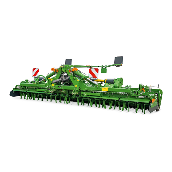
Summary of Contents for Amazone KG 4002-2
- Page 1 Translation of the original operating instructions Rotary cultivator KG 4002-2 KG 5002-2 KG 6002-2 SmartLearning www.amazone.de...
- Page 2 Please enter the identification data of the implement. The identification data can be found on the rating plate.
-
Page 3: Table Of Contents
Universal joint shaft guard 5.10 Oils and filling capacities 4.4.2 Tool protection 5.11 Maximum transport speed 4.4.3 Frame transport lock 4.4.4 Roller transport lock Warning symbols 4.5.1 Positions of the warning symbols MG6750-EN-II | I.1 | 27.07.2023 | © AMAZONE... - Page 4 10.1.4 Checking the wheel bolt tightening 6.8.12 Adjusting the scraper to the roller torque Preparing the machine for road 10.1.5 Checking the tyre inflation pressure travel 10.1.6 Checking the tines MG6750-EN-II | I.1 | 27.07.2023 | © AMAZONE...
- Page 5 11 Disposing of the implement 12 Loading the implement 12.1 Loading the implement with a crane 12.2 Lashing the implement 13 Appendix 13.1 Bolt tightening torques 13.2 Other applicable documents 14 Directories 14.1 Glossary 14.2 Index MG6750-EN-II | I.1 | 27.07.2023 | © AMAZONE...
-
Page 7: About This Operating Manual
WARNING Indicates a possible threat with moderate risk for severe physical injury or death. CAUTION Indicates a threat with low risk for light or moderately severe physical injuries. MG6750-EN-II | I.1 | 27.07.2023 | © AMAZONE... -
Page 8: Further Instructions
Example: 1. Instruction 1 2. Instruction 2 1.2.3.2 Instructions and responses CMS-T-005678-B.1 Reactions to instructions are marked with an arrow. Example: 1. Instruction 1 Reaction to instruction 1 2. Instruction 2 MG6750-EN-II | I.1 | 27.07.2023 | © AMAZONE... - Page 9 CMS-T-00013932-B.1 WORKSHOP WORK Identifies maintenance work that must be performed at a workshop that is adequately equipped in terms of agricultural technology, safety and environmental technology by specialist personnel with appropriate training. MG6750-EN-II | I.1 | 27.07.2023 | © AMAZONE...
-
Page 10: Lists
A list of other applicable documents can be found in the Appendix. 1.4 Digital operating manual CMS-T-00002024-B.1 The digital operating manual and e-learning can be downloaded from the Info Portal on the AMAZONE website. 1.5 Your opinion is important CMS-T-000059-C.1 AMAZONEN-WERKE H. Dreyer SE & Co. KG Dear reader, our operating manuals are updated regularly. -
Page 11: Safety And Responsibility
The person must be familiar with safe driving of vehicles. For road travel, the person knows the relevant road traffic regulations and has the prescribed driving permit. MG6750-EN-II | I.1 | 27.07.2023 | © AMAZONE... - Page 12 Agricultural helpers can be e.g.: Seasonal workers and labourers Prospective farmers in training Employees of the farmer (e.g. tractor driver) Family members of the farmer MG6750-EN-II | I.1 | 27.07.2023 | © AMAZONE...
- Page 13 Without correct preparation according to this operating manual, operational safety of the machine is not ensured. This can result in accidents and serious personal injury or even death. Prepare the machine according to this operating manual. MG6750-EN-II | I.1 | 27.07.2023 | © AMAZONE...
- Page 14 Use only protective equipment that is in proper condition and offers effective protection. Adjust the personal protective equipment to the person, e.g. the size. Observe the manufacturer's instructions regarding operating materials, seed, fertiliser, crop protection products, and cleaning agents. MG6750-EN-II | I.1 | 27.07.2023 | © AMAZONE...
-
Page 15: Knowing And Preventing Dangers
Never look for leaks with your bare hands. Keep your body and face away from leaks. If liquids penetrate the body, consult a doctor immediately. MG6750-EN-II | I.1 | 27.07.2023 | © AMAZONE... - Page 16 When the drives are switched off, machine parts can continue running and cause serious personal injury or death. Before approaching the machine, wait until any machine parts that are still running have come to a stop. Only touch machine parts that are standing still. MG6750-EN-II | I.1 | 27.07.2023 | © AMAZONE...
-
Page 17: Safe Operation And Handling Of The Machine
Use only suitable tractors for coupling and transporting the implement. When the implement is coupled onto the tractor, make sure that the tractor's connecting device meets the implement requirements. Couple the implement properly to the tractor. MG6750-EN-II | I.1 | 27.07.2023 | © AMAZONE... - Page 18 If the machine is not properly prepared for road travel, it can result in serious traffic accidents. Check the lighting and identification for road travel for proper function. Remove coarse dirt from the implement. Follow the instructions in the section "Preparing the implement for road travel". MG6750-EN-II | I.1 | 27.07.2023 | © AMAZONE...
-
Page 19: Safe Maintenance And Modification
To ensure that the operating permit remains valid in accordance with national and international regulations, ensure that the specialist workshop only uses conversion parts, spare parts and special equipment approved by AMAZONE. MG6750-EN-II | I.1 | 27.07.2023 | © AMAZONE... - Page 20 Remove the ignition key and carry it with you. Remove the key from the battery circuit breaker. Wait until all parts that are still running come to a stop and that hot parts cool down. MG6750-EN-II | I.1 | 27.07.2023 | © AMAZONE...
- Page 21 Never linger under raised implement parts. If you have to work on or under raised machine parts, lower the implement parts or secure the raised implement parts with a mechanical support or hydraulic locking device. MG6750-EN-II | I.1 | 27.07.2023 | © AMAZONE...
- Page 22 CMS-T-00002325-B.1 Special equipment, accessories, and spare parts Special equipment, accessories, and spare parts that do not meet AMAZONE requirements can impede the operational safety of the implement and cause accidents. Only use original parts or parts that meet AMAZONE requirements.
-
Page 23: Safety Routines
If you are not sure if the protective equipment is properly installed and functional, have the protective equipment checked by a qualified specialist workshop. Make sure that the protective devices are properly installed and functional before any work on the implement. Replace damaged protective equipment. MG6750-EN-II | I.1 | 27.07.2023 | © AMAZONE... - Page 24 When climbing up and down, never hold onto the control elements. Accidental actuation of control elements can unintentionally activate potentially dangerous functions. When climbing down, never jump off of the machine. MG6750-EN-II | I.1 | 27.07.2023 | © AMAZONE...
-
Page 25: Intended Use
AMAZONE. Uses other than those specified under the intended use are considered as improper. The manufacturer is not liable for any damage resulting from improper use, solely the operator is responsible. MG6750-EN-II | I.1 | 27.07.2023 | © AMAZONE... -
Page 26: Product Description
Tines Wheel mark eradicator Transport frame locking device 3-point extension Centre line eradicator Rating plate on the implement 10 Front tool protection Universal joint shaft 11 Lighting and identification for road travel MG6750-EN-II | I.1 | 27.07.2023 | © AMAZONE... -
Page 27: Function Of The Implement
2 . For operation as a seeding combination, the soil tillage implement can be combined with a seeding unit or a pack top seed drill. CMS-I-00002954 MG6750-EN-II | I.1 | 27.07.2023 | © AMAZONE... -
Page 28: Special Equipment
CMS-I-00002948 4.3 Special equipment CMS-T-00003990-B.1 Centre line eradicator Track marker Wheel mark eradicator Lighting and identification for road travel Oil cooler Transport frame Hydraulic working depth adjustment MG6750-EN-II | I.1 | 27.07.2023 | © AMAZONE... -
Page 29: Protective Equipment
The tool guard contains side guide plates 1 und protective plates 2 . CMS-I-00003296 Towards the rear, the tool guard contains a guard tube 1 and trailing roller 2 . CMS-I-00003297 MG6750-EN-II | I.1 | 27.07.2023 | © AMAZONE... -
Page 30: Frame Transport Lock
2 from swinging excessively with the trailing roller in the folded state. CMS-I-00002932 The transport lock 1 prevents the inner carrying arms 2 from swinging excessively with the trailing roller in the folded state. CMS-I-00002933 MG6750-EN-II | I.1 | 27.07.2023 | © AMAZONE... -
Page 31: Warning Symbols
4 | Product description Warning symbols 4.5 Warning symbols CMS-T-00003995-G.1 4.5.1 Positions of the warning symbols CMS-T-00003996-E.1 MD075 MD094 MD100 MD075 MD089 MD155 MD079 MD097 MD079 MD082 MD082 MD087 MD087 MD089 MD078 MD155 MD076 CMS-I-00002937 MG6750-EN-II | I.1 | 27.07.2023 | © AMAZONE... -
Page 32: Layout Of The Warning Symbols
A warning symbol consists of two fields: Field 1 shows the following: A pictogram depicting the danger area, CMS-I-00000416 surrounded by triangular safety symbol The order number Field 2 shows a pictogram depicting how to avoid the danger. MG6750-EN-II | I.1 | 27.07.2023 | © AMAZONE... -
Page 33: Description Of The Warning Symbols
Danger due to ejected material As long as engine of the tractor or machine is running, stay away from the danger area. Make sure that there is nobody standing in the danger area. CMS-I-000076 MG6750-EN-II | I.1 | 27.07.2023 | © AMAZONE... - Page 34 Maintain an adequately safe distance from electrical transmission lines, especially when folding or unfolding implement parts. CMS-I-000692 Please note that the voltage can flash over when the distance is too small. MG6750-EN-II | I.1 | 27.07.2023 | © AMAZONE...
- Page 35 Before you actuate the tractor hydraulic system, instruct persons away from the area between the tractor and the implement. Actuate the tractor hydraulic system only from the designated work station. CMS-I-000139 MG6750-EN-II | I.1 | 27.07.2023 | © AMAZONE...
- Page 36 Risk of crushing die to swivelling parts of the implement As long as the tractor engine is running, maintain an adequate safety distance from swivelling implement parts. Make sure that there is nobody standing close to swivelling parts. CMS-I-00003312 MG6750-EN-II | I.1 | 27.07.2023 | © AMAZONE...
- Page 37 CMS-I-00003656 MD 155 Risk of accident and machine damage during transport due to improperly secured machine Only attach the lashing belts at the marked lashing positions for transporting the machine. CMS-I-00000450 MG6750-EN-II | I.1 | 27.07.2023 | © AMAZONE...
-
Page 38: Threaded Cartridge
The threaded cartridge contains the following items: Documents Aids CMS-I-00002306 4.7 3-point mounting frame CMS-T-00004004-A.1 Category 3 lower link mounting Spacer discs for the ball sleeves Category 3 top link mounting Additional Category 3 top link mounting CMS-I-00002943 MG6750-EN-II | I.1 | 27.07.2023 | © AMAZONE... -
Page 39: Rating Plate On The Implement
4.9 Universal operating tool CMS-T-00001735-C.1 Setting work on the implement is performed with the universal operating tool 1 . The universal operating tool is parked in a holder on the implement frame. CMS-I-00001082 MG6750-EN-II | I.1 | 27.07.2023 | © AMAZONE... -
Page 40: Universal Joint Shaft Locking Mechanism
4.11.1 Rear lighting and identification for road travel CMS-T-00001498-F.1 Warning signs Reflector, red Rear lights, brake lights, and turn indicators Reflector, yellow CMS-I-00004545 NOTE The lighting and identification for road travel can vary depending on the national regulations. MG6750-EN-II | I.1 | 27.07.2023 | © AMAZONE... -
Page 41: Front Lighting And Identification
Reflector, white Side marker lights CMS-I-00002940 NOTE The lighting and identification for road travel can vary depending on the national regulations. 4.11.3 Additional license plate CMS-T-00003999-C.1 Licence plate lighting Licence plate holder CMS-I-00003163 MG6750-EN-II | I.1 | 27.07.2023 | © AMAZONE... -
Page 42: T-Pack Tyre Packer
2x TRW 2000-600 2x TRW 2500-600 2x TRW 3000-600 2-tube roller frame Wedge ring roller 2x KW 2000-580 2x KW 2500-580 2x KW 3000-580 Wedge ring roller 2x KWM 3000-600 with matrix tyres MG6750-EN-II | I.1 | 27.07.2023 | © AMAZONE... -
Page 43: Packer Rollers From Other Manufacturers
20 minutes, the fan changes its direction of rotation for 40 seconds. The air current eliminates any dirt from the cooler fins. The oil pump 3 is driven by the gearbox. CMS-I-00002962 MG6750-EN-II | I.1 | 27.07.2023 | © AMAZONE... -
Page 44: Technical Data
5.2 Permissible total weight CMS-T-00006278-B.1 KG 4002-2 KG 5002-2 KG 6002-2 3,900 kg 5,850 kg 6,590 kg 5.3 Mounting category CMS-T-00004086-B.1 Solo operation Seeding combination Category 3/4N Category 4N 5.4 Working speed CMS-T-00004087-B.1 4-12 km/h MG6750-EN-II | I.1 | 27.07.2023 | © AMAZONE... -
Page 45: Working Depth
Depending on the implement equipment: Control units 3x double-acting Pressure-free return flow Do not exceed a back pressure of 5 bar. Universal joint shaft Speed 540/750/1000 rpm Direction of rotation Clockwise MG6750-EN-II | I.1 | 27.07.2023 | © AMAZONE... -
Page 46: Noise Development Data
5.9 Lubricants CMS-T-00002396-B.1 Manufacturer Lubricant ARAL Aralub HL2 FINA Marson L2 ESSO Beacon 2 SHELL Retinax A 5.10 Oils and filling capacities CMS-T-00004158-C.1 NOTE Specifications for the manual transmission and the angular gearboxes: MG6750-EN-II | I.1 | 27.07.2023 | © AMAZONE... - Page 47 The following table contains several gear oil types that comply with the standard. Manufacturer Gear oil Factory filling: Wintershall ERSOLAN 460 Agip Blasia 460 ARAL Degol BG 460 Autol Precis GEP 460 MG6750-EN-II | I.1 | 27.07.2023 | © AMAZONE...
-
Page 48: Maximum Transport Speed
CMS-T-00009156-B.1 40 km/h 5.12 Permissible payload CMS-T-00011018-D.1 Permissible payload for operation Permissible payload G : Permissible technical implement weight according to the rating plate [ kg] : Determined tare weight [ kg] MG6750-EN-II | I.1 | 27.07.2023 | © AMAZONE... -
Page 49: Preparing The Machine
Total weight of front-mounted implement or front ballast Permissible total weight of rear-mounted implement or rear ballast Distance between the centre of gravity of the front-mounted implement or the front ballast and the centre of the front axle MG6750-EN-II | I.1 | 27.07.2023 | © AMAZONE... - Page 50 T b 0,2 T b Vmin Vmin Vmin CMS-I-00000513 2. Calculate the actual front axle load. × × - × G a b T b G c + d Vtat Vtat Vtat CMS-I-00000516 MG6750-EN-II | I.1 | 27.07.2023 | © AMAZONE...
- Page 51 Tyre load according to according to capacity for two tractor operating calculation tractor tyres manual ≤ Minimum front ballasting ≤ Total weight ≤ ≤ Front axle load ≤ ≤ Rear axle load MG6750-EN-II | I.1 | 27.07.2023 | © AMAZONE...
-
Page 52: Attaching The Backstop Profiles For The Lower Links
6.3 Preparing the universal joint shaft CMS-T-00005128-B.1 1. Have the length of the universal joint shaft adjusted by a specialist workshop. 2. Have the universal joint shaft installed by a specialist workshop. MG6750-EN-II | I.1 | 27.07.2023 | © AMAZONE... -
Page 53: Installing The Universal Joint Shaft On The Implement
6. Swivel the bracket under the universal joint shaft. 7. Put the universal joint shaft in the bracket. 8. Secure the guard tube with the safety chain 1 on the fastening point 2 . MG6750-EN-II | I.1 | 27.07.2023 | © AMAZONE... -
Page 54: Using The Centre Line Eradicator
1 in position 1. When the lamp lights up, put the "beige" tractor control unit in float position. The hydraulic top link is now in float position. CMS-I-00003249 MG6750-EN-II | I.1 | 27.07.2023 | © AMAZONE... -
Page 55: Coupling The Implement
6.7.1 Driving the tractor towards the implement CMS-T-00005794-D.1 Enough space must remain between the tractor and implement so that the supply lines can be coupled without obstructions. Drive the tractor towards the implement, leaving a sufficient distance. CMS-I-00004045 MG6750-EN-II | I.1 | 27.07.2023 | © AMAZONE... -
Page 56: Coupling The 3-Point Mounting Frame
Free oil flow in the tractor control Floating unit Designation Function Tractor control unit Unfold Folding the Green Double-acting implement Fold Increase Working Beige depth of the Double-acting tool tines Reduce Unfold Yellow Track marker Double-acting Fold MG6750-EN-II | I.1 | 27.07.2023 | © AMAZONE... - Page 57 Install the supplied coupling sleeve on the pressureless hydraulic oil return. 1. Depressurise the hydraulic system between the tractor and the implement using the tractor control unit. 2. Clean the hydraulic plugs. MG6750-EN-II | I.1 | 27.07.2023 | © AMAZONE...
-
Page 58: Coupling The Power Supply
1. Pull back the drawing sleeve on the tractor side. 2. Push the universal joint shaft onto the tractor PTO shaft. The drawing sleeve engages. 3. Swivel the bracket 1 in the parking position. 4. Secure the bracket. CMS-I-00003520 MG6750-EN-II | I.1 | 27.07.2023 | © AMAZONE... -
Page 59: Coupling The Power Supply For Additional Fan
As soon as voltage is applied to the 12V socket, the additional fan starts rotating. Every 20 minutes, the fan changes its direction of rotation for 40 seconds. The air current eliminates any dirt from the cooler fins CMS-I-00003084 MG6750-EN-II | I.1 | 27.07.2023 | © AMAZONE... -
Page 60: Preparing The Implement For Operation
Push the gear lever into the gearbox housing as far as it will go To engage the second gear, Pull the gear lever out of the gearbox housing as far as it will go. CMS-I-00003032 MG6750-EN-II | I.1 | 27.07.2023 | © AMAZONE... - Page 61 4. Remove the peripheral cover screws 2 . ENVIRONMENTAL INFORMATION Danger due to escaping oil Collect any escaping oil. Dispose of cleaning agents for removing oil in an environmentally friendly manner. CMS-I-00003025 5. Remove the gearbox cover. MG6750-EN-II | I.1 | 27.07.2023 | © AMAZONE...
-
Page 62: Adjusting The Section End Position
6. Unfold the implement sections. The setting screws must touch the contact surface 3 simultaneously. 7. Tighten the lock nut. 8. Make the same setting for the opposite side of the implement. MG6750-EN-II | I.1 | 27.07.2023 | © AMAZONE... -
Page 63: Using The Centre Line Eradicator
The soil tillage implement 4 is supported by the carrying arms 2 for the trailing roller 1 . To adjust the working depth, the depth setting pin 3 is inserted in the desired hole. CMS-I-00002941 MG6750-EN-II | I.1 | 27.07.2023 | © AMAZONE... - Page 64 5. Insert the depth setting pin in the desired position 6. Secure the depth setting pin with the linch pin. 7. Make the same setting for the opposite side of the implement. MG6750-EN-II | I.1 | 27.07.2023 | © AMAZONE...
- Page 65 To adjust the setting of the levelling board, see section "Adjusting the working depth of the levelling board". To adjust the setting of the side guide plates, see section "Adjusting the working depth of the side guide plates". MG6750-EN-II | I.1 | 27.07.2023 | © AMAZONE...
-
Page 66: Working Depth
To adjust the setting of the levelling board, see section "Adjusting the working depth of the levelling board". To adjust the setting of the side guide plates, see section "Adjusting the working depth of the side guide plates". MG6750-EN-II | I.1 | 27.07.2023 | © AMAZONE... -
Page 67: Levelling Board
The locking mechanism must engage. 5. Make the same setting for the opposite side of the implement. To check the setting, Work for approx. 30 m at working speed and then check the work pattern. MG6750-EN-II | I.1 | 27.07.2023 | © AMAZONE... -
Page 68: Adjusting The Working Depth Of The Side Guide Plates
6. Tighten the bolts. 7. Make the same setting for the opposite side of the implement. To check the setting, Work for approx. 30 m at working speed and then check the work pattern. MG6750-EN-II | I.1 | 27.07.2023 | © AMAZONE... -
Page 69: Adjusting The T-Pack Tyre Packer
Very small swinging Lower - range 1. Unfold the implement sections on the field. 2. Raise the implement. The depth setting pins 3 are no longer resting on the carrying arms 4 . CMS-I-00005990 MG6750-EN-II | I.1 | 27.07.2023 | © AMAZONE... -
Page 70: Preparing The Wheel Mark
8. Secure the locking pin with the linch pin. 9. Install the shear bolt. 10. Install the nut and tighten it. To check the setting: Work for approx. 30 m at working speed and then check the work pattern. MG6750-EN-II | I.1 | 27.07.2023 | © AMAZONE... - Page 71 6. Secure the wheel mark eradicator with the locking pin. 7. Secure the locking pin with the linch pin. To check the setting: drive for 30 m at working speed and then check the work pattern. MG6750-EN-II | I.1 | 27.07.2023 | © AMAZONE...
- Page 72 Shallow loosening and levelling of High pulling force Wing coulter medium, silty soils requirement Medium pulling force Heart-shaped coulter Medium-depth loosening of various soils requirement Low pulling force Narrow coulter Deep loosening of light soils requirement MG6750-EN-II | I.1 | 27.07.2023 | © AMAZONE...
-
Page 73: Preparing The Track Marker For Operation
Both track markers are raised when turning at the end of the field. Both track markers must be raised for transporting the implement. The track markers are hydraulically locked. CMS-I-00002951 MG6750-EN-II | I.1 | 27.07.2023 | © AMAZONE... - Page 74 3. Move the track marker disc 1 to the desired position. 4. Tighten the bolts. If the setting range is not enough: Remove the bolt 3 . 6. Move the holder 4 to the desired position. CMS-I-00007972 MG6750-EN-II | I.1 | 27.07.2023 | © AMAZONE...
-
Page 75: Adjusting The Spring Tension Of The Side Guide Plates
The swivelling side panel deflects upwards on obstacles. The dead weight of the side panel and a tension spring bring the side panel back into working position. The pre-tensioning of the tension spring is adjustable. MG6750-EN-II | I.1 | 27.07.2023 | © AMAZONE... -
Page 76: Adjusting The Scraper To The Roller
0,5 mm to 4 mm CMS-I-00000933 Trapeze ring roller TRW 0,5 mm to 4 mm To check the distance, rotate the roller 2 . 4. Tighten the bolt. 5. Make the same setting for all scrapers. MG6750-EN-II | I.1 | 27.07.2023 | © AMAZONE... -
Page 77: Preparing The Machine For Road Travel
2 of the trailing roller in a folded state. 4. Before driving off, check that the roller transport lock is engaged. If the roller transport lock is not engaged, move the roller outwards until the roller transport lock engages. CMS-I-00002932 MG6750-EN-II | I.1 | 27.07.2023 | © AMAZONE... -
Page 78: Coupling The Transport Frame
The transport frame 3 is locked. 8. Secure the locking lever with a linch pin. 9. Lower the implement along with the transport frame. The wheels of the transport frame are touching the ground. CMS-I-00003046 MG6750-EN-II | I.1 | 27.07.2023 | © AMAZONE... -
Page 79: Transport Width With Installed Potato Tines
The vehicle owner and driver are responsible for compliance with the regulations. Observe the transport width when the potato tines are installed. MG6750-EN-II | I.1 | 27.07.2023 | © AMAZONE... -
Page 80: Telescoping The Track Marker
2. Raise the implement. CMS-I-00005990 The depth setting pins 3 are no longer resting on the carrying arms 4 . 3. Secure the tractor and implement. 4. Remove the linch pin 1 . MG6750-EN-II | I.1 | 27.07.2023 | © AMAZONE... - Page 81 5. Insert the depth setting pin at the desired position 6. Secure the depth setting pin with the linch pin. 7. Make the same setting for the opposite side of the implement. CMS-I-00002963 MG6750-EN-II | I.1 | 27.07.2023 | © AMAZONE...
-
Page 82: Using The Machine
To extend the hydraulic top link, see section "Using the hydraulic top link". The transport wheel 2 is touching the ground. To lock the hydraulic top link, see section "Using the hydraulic top link". MG6750-EN-II | I.1 | 27.07.2023 | © AMAZONE... -
Page 83: Unfolding The Implement
1. Lower the implement until it is just above the field. When working with the implement switched on, it must be ensured that the tines touch the soil. 2. Switch on the tractor PTO shaft. MG6750-EN-II | I.1 | 27.07.2023 | © AMAZONE... -
Page 84: Checking The Set Working Depth
Lifting the track marker causes the tramline counter to be advanced. To correct the position of the tramline counter, actuate the "yellow" tractor control unit several times until the tramline counter detects the correct tramline. MG6750-EN-II | I.1 | 27.07.2023 | © AMAZONE... -
Page 85: Eliminating Faults
The wheel mark eradicator collision The wheel mark eradicator has see page 82 protection is triggered encountered a solid obstacle. The shear bolt is torn and the wheel mark eradicator folded to the rear. MG6750-EN-II | I.1 | 27.07.2023 | © AMAZONE... - Page 86 An obstacle is jammed between the tines: 1. Raise the implement. 2. Secure the tractor and implement. 3. Wait until the tool carriers come to a stop. 4. Remove the obstacle between the tines. MG6750-EN-II | I.1 | 27.07.2023 | © AMAZONE...
- Page 87 1000 rpm. The additional fan is not rotating CMS-T-00004172-B.1 1. Disconnect the power supply. 2. Allow the regulator for the additional fan to cool down. MG6750-EN-II | I.1 | 27.07.2023 | © AMAZONE...
- Page 88 2. Remove the damaged bolt 3 . 3. Fold the wheel mark eradicator 2 into working position. NOTE Only use original bolts as a replacement. 4. Install the spare bolt. CMS-I-00004507 5. Install the nut and tighten it. MG6750-EN-II | I.1 | 27.07.2023 | © AMAZONE...
-
Page 89: Parking The Machine
Actuate the pull rope and actuate the "green 1" tractor control unit. When the implement sections have reached the end position, CMS-I-00002993 Release the pull rope and put the tractor control unit into float position. MG6750-EN-II | I.1 | 27.07.2023 | © AMAZONE... -
Page 90: Lowering The Implement
Park the implement sections on a level surface with solid ground. 9.3 Uncoupling the power supply CMS-T-00001402-H.1 1. Pull out the plug 1 for the power supply. CMS-I-00001048 2. Hang the plugs 1 in the hose cabinet. CMS-I-00001248 MG6750-EN-II | I.1 | 27.07.2023 | © AMAZONE... -
Page 91: Uncoupling The Additional Fan Power Supply
3. Disconnect the hydraulic hose lines 1 . 4. Put the dust caps on the hydraulic sockets. CMS-I-00001065 5. Hang the hydraulic hose lines 1 in the hose cabinet. CMS-I-00001250 MG6750-EN-II | I.1 | 27.07.2023 | © AMAZONE... -
Page 92: Uncoupling The Universal Joint Shaft
2. Release the top link 1 . 3. Uncouple the top link 1 from the implement. 4. Release the lower links 2 . 5. Uncouple the lower links 2 from the implement from the tractor seat. CMS-I-00001249 MG6750-EN-II | I.1 | 27.07.2023 | © AMAZONE... -
Page 93: Repairing The Machine
Checking the lower link pins and top link pins see page 88 Every 6 months Ratchet clutch maintenance see page 97 Every 50 operating hours Checking the tines see page 90 MG6750-EN-II | I.1 | 27.07.2023 | © AMAZONE... -
Page 94: Checking The Lower Link Pins And Top Link Pins
Criteria for visual inspection of lower link pins and top link pins: Cracks Fractures Permanent deformations Permissible wear: 2 mm 1. Check the lower link pins and top link pins for the listed criteria. 2. Replace worn pins. MG6750-EN-II | I.1 | 27.07.2023 | © AMAZONE... -
Page 95: Checking The Hydraulic Hose Lines
10.1.4 Checking the wheel bolt tightening torque CMS-T-00003578-C.1 INTERVAL After initial operation Every 100 operating hours Every 12 months Tyres Tightening torque Tyres 10/75-15.3-AS 300 Nm Check the wheel bolt tightening torque. MG6750-EN-II | I.1 | 27.07.2023 | © AMAZONE... -
Page 96: Checking The Tyre Inflation Pressure
10.1.6 Checking the tines CMS-T-00005050-A.1 INTERVAL Every 50 operating hours 1. Determine the length of the tines. If the minimum length of the tines is undercut, replace the tines. CMS-I-00003613 MG6750-EN-II | I.1 | 27.07.2023 | © AMAZONE... -
Page 97: Replacing The Tines
CMS-I-00003470 4. Pay attention to the alignment of the tine. 5. Install the new tine 2 . 6. Fasten the tine with the pin. 7. Secure the tine with the linch pin. MG6750-EN-II | I.1 | 27.07.2023 | © AMAZONE... -
Page 98: Checking The Oil Level In The Manual Transmission
When the oil level is visible between the CMS-I-00003040 markings on the dipstick, install the oil dipstick with a new sealing ring. 6. install the oil dipstick with a new sealing ring. MG6750-EN-II | I.1 | 27.07.2023 | © AMAZONE... -
Page 99: Checking The Oil Level In The Spur Gear Trough
5. Install the cover with the ventilation pipe. 6. Install the peripheral cover screws. 7. Check the second spur gear trough. NOTE There is no need to change the oil in the spur gear trough. MG6750-EN-II | I.1 | 27.07.2023 | © AMAZONE... -
Page 100: Changing The Oil Of The Manual Transmission
5. Install the oil drain plug with a new sealing ring. 6. Refill oil according to the specification 3 and the technical data. 7. install the refill screw with a new sealing ring. MG6750-EN-II | I.1 | 27.07.2023 | © AMAZONE... -
Page 101: Changing The Oil Of The Angular Gearbox
5. Install the oil drain plug with a new sealing ring. 6. Refill oil according to the specification 2 and the technical data. 7. install the oil dipstick with a new sealing ring. MG6750-EN-II | I.1 | 27.07.2023 | © AMAZONE... -
Page 102: Replacing The Oil Filter
6. Install the sealing ring on the oil filter cartridge. 7. Install the oil filter cartridge. 8. Tighten the bolts. To check the oil level, see "Checking the oil level in the manual transmission". MG6750-EN-II | I.1 | 27.07.2023 | © AMAZONE... -
Page 103: Checking The Wheel Mark Eradicator Coulter
See section "Changing the wheel mark eradicator coulter". 10.1.15 Ratchet clutch maintenance CMS-T-00004584-A.1 INTERVAL Every 6 months Perform maintenance on the ratchet clutches 1 according to the instructions from the universal joint shaft manufacturer CMS-I-00003044 MG6750-EN-II | I.1 | 27.07.2023 | © AMAZONE... -
Page 104: Universal Joint Shaft Maintenance
Maintaining the machine 10.1.16 Universal joint shaft maintenance CMS-T-00004585-A.1 INTERVAL Every 50 operating hours as required Perform maintenance on the universal joint shaft according to the instructions from the universal joint shaft manufacturer MG6750-EN-II | I.1 | 27.07.2023 | © AMAZONE... -
Page 105: Lubricating The Implement
Only grease the implement with the lubricants listed in the technical data. CMS-I-00002270 Press the dirty grease completely out of the bearings. MG6750-EN-II | I.1 | 27.07.2023 | © AMAZONE... -
Page 106: Overview Of Lubrication Points
10 | Repairing the machine Lubricating the implement 10.2.1 Overview of lubrication points CMS-T-00004121-C.1 CMS-I-00003009 Every 50 operating hours / Every 6 months CMS-I-00003003 CMS-I-00003004 MG6750-EN-II | I.1 | 27.07.2023 | © AMAZONE... - Page 107 10 | Repairing the machine Lubricating the implement CMS-I-00003005 CMS-I-00003002 CMS-I-00003006 Every 100 operating hours / Every 6 months CMS-I-00003007 CMS-I-00006005 MG6750-EN-II | I.1 | 27.07.2023 | © AMAZONE...
-
Page 108: Cleaning The Implement
Always maintain a minimum distance of 30 cm between the high-pressure nozzle and the implement. Do not exceed a water pressure of 120 bar. Clean the machine with a high-pressure cleaner or a hot water high-pressure cleaner. MG6750-EN-II | I.1 | 27.07.2023 | © AMAZONE... -
Page 109: Disposing Of The Implement
2. Return batteries to the distributor Dispose of batteries at a collection point. 3. Put recyclable materials in the recycling. 4. Treat operating materials like hazardous waste. WORKSHOP WORK 5. Dispose of the coolant. MG6750-EN-II | I.1 | 27.07.2023 | © AMAZONE... -
Page 110: Loading The Implement
Only attach the slings for lifting at the marked lashing points. CMS-I-00003269 REQUIREMENTS The implement is unfolded 1. Attach the slings for lifting on the intended lashing points. 2. Slowly lift the implement. MG6750-EN-II | I.1 | 27.07.2023 | © AMAZONE... -
Page 111: Lashing The Implement
The implement is unfolded 1. Put the implement on the transport vehicle. 2. Attach the lashing straps at the marked points. 3. Lash down the implement in compliance with the national regulations for load securing. MG6750-EN-II | I.1 | 27.07.2023 | © AMAZONE... -
Page 112: Appendix
380 Nm 290 Nm 405 Nm 485 Nm 27 mm M18x1.5 325 Nm 460 Nm 550 Nm 410 Nm 580 Nm 690 Nm 30 mm M20x1.5 460 Nm 640 Nm 770 Nm MG6750-EN-II | I.1 | 27.07.2023 | © AMAZONE... -
Page 113: Other Applicable Documents
4.9 Nm 174 Nm 8.4 Nm 242 Nm 20.4 Nm 342 Nm 40.7 Nm 470 Nm 70.5 Nm 589 Nm 13.2 Other applicable documents CMS-T-00004153-A.1 Tractor operating manual Universal joint shaft operating manual MG6750-EN-II | I.1 | 27.07.2023 | © AMAZONE... -
Page 114: Directories
Tractor In this operating manual, the designation tractor is always used, even for other agricultural tractor units. Implements are mounted on the tractor or towed by the tractor. MG6750-EN-II | I.1 | 27.07.2023 | © AMAZONE... -
Page 115: Index
Bolt tightening torques Headlands Hydraulic hose lines checking Changing the oil coupling Angular gearbox uncoupling Manual transmission Oils and filling capacities Hydraulic system coupling checking Hydraulic hose lines Lower link pin Top link pin MG6750-EN-II | I.1 | 27.07.2023 | © AMAZONE... - Page 116 Ratchet clutch Mounting category Rating plate on the implement Description Noise development data Rear axle load calculation Replacing the oil filter Oil cooler Roller Description Adjusting the scraper Operation Roller transport lock MG6750-EN-II | I.1 | 27.07.2023 | © AMAZONE...
- Page 117 Adjusting the track marker length telescoping Tractor Calculating the required tractor characteristics 43 Transport frame coupling uncoupling Transport speed Transport width with installed potato tines Tyre load capacity calculation Uncoupling the universal joint shaft MG6750-EN-II | I.1 | 27.07.2023 | © AMAZONE...
- Page 120 AMAZONEN-WERKE H. DREYER SE & Co. KG Postfach 51 49202 Hasbergen-Gaste Germany +49 (0) 5405 501-0 amazone@amazone.de www.amazone.de MG6750-EN-II | I.1 | 27.07.2023 | © AMAZONE...
Need help?
Do you have a question about the KG 4002-2 and is the answer not in the manual?
Questions and answers