Table of Contents
Advertisement
Quick Links
Catros 4002-2TS
Catros 5002-2TS
Catros 6002-2TS
MG5422
BAG0155.4 05.19
Printed in Germany
en
Operating Manual
AMAZONE
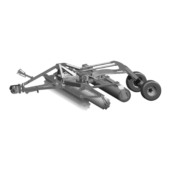
Trailed compact disc cultivator
with swivelling running gear
+
Catros
4002-2TS
+
Catros
5002-2TS
+
Catros
6002-2TS
Please read and follow this
operating manual before putting
the machine into operation.
Keep it in a safe place for
future use.
Advertisement
Table of Contents

Related Manuals for Amazone Catros 4002-2TS


Summary of Contents for Amazone Catros 4002-2TS
- Page 1 Operating Manual AMAZONE Catros 4002-2TS Catros 4002-2TS Catros 5002-2TS Catros 5002-2TS Catros 6002-2TS Catros 6002-2TS Trailed compact disc cultivator with swivelling running gear Please read and follow this operating manual before putting MG5422 the machine into operation. BAG0155.4 05.19 Keep it in a safe place for Printed in Germany future use.
- Page 2 Reading the instruction Manual and following it should seem to be in- convenient and superfluous as it is not enough to hear from others and to realize that a machine is good, to buy it and to believe that now everything should work by itself.
- Page 3 +49 5405 501-0 E-mail: amazone@amazone.de Spare part orders Spare parts lists are freely accessible in the spare parts portal at www.amazone.de. Please send orders to your AMAZONE dealer. Formalities of the operating manual Document number: MG5422 Compilation date: 05.19 ...
- Page 4 Dear Reader We update our operating manuals regularly. Your suggestions for improvement help us to create ever more user-friendly manuals. AMAZONEN-WERKE H. DREYER GmbH & Co. KG Postfach 51 D-49202 Hasbergen Phone: +49 5405 501-0 E-mail: amazone@amazone.de Catros BAG0155.4 05.19...
-
Page 5: Table Of Contents
Table of Contents User information ..................8 Purpose of the document ......................8 Locations in the operating manual ................... 8 Diagrams used ......................... 8 General safety instructions ................. 9 Obligations and liability ......................9 Representation of safety symbols ..................11 Organisational measures ....................... - Page 6 Table of Contents 5.6.2 Coupling the brake and supply lines ..................51 5.6.3 Uncoupling the brake and supply lines ................. 52 Hydraulic service brake system .................... 53 5.7.1 Coupling the hydraulic service brake system ................ 53 5.7.2 Uncoupling the hydraulic service brake system ..............53 5.7.3 Emergency brake ........................
- Page 7 Table of Contents 12.8 Checking the roller ....................... 104 12.9 Disc carrier fixture ........................ 104 12.10 Axle ............................104 12.11 Tyres/wheels ........................105 12.11.1 Tyre pressures ........................105 12.11.2 Mounting tyres (workshop work) ..................106 12.12 Check the coupling device ....................107 12.13 Hydraulic cylinder for foldable booms ..................
-
Page 8: User Information
User information User information The "User information" section supplies information on using the op- erating manual. Purpose of the document This operating manual • Describes the operation and maintenance of the machine. • Provides important information on safe and efficient handling of the machine. -
Page 9: General Safety Instructions
General safety instructions General safety instructions This section contains important information on safe operation of the machine. Obligations and liability Comply with the instructions in the operating manual Knowledge of the basic safety information and safety regulations is a basic requirement for safe handling and fault-free machine operation. Obligations of the operator The operator is obliged only to let those people work with/on the ma- chine who... - Page 10 General safety instructions Risks in handling the machine The machine has been constructed to the state-of-the art and the recognised rules of safety. However, there may be risks and re- strictions which occur when operating the machine • For the health and safety of the user or third persons, •...
-
Page 11: Representation Of Safety Symbols
General safety instructions Representation of safety symbols Safety instructions are indicated by the triangular safety symbol and the highlighted signal word. The signal word (DANGER, WARNING, CAUTION) describes the gravity of the risk and has the following sig- nificance: DANGER Indicates an immediate high risk, which will result in death or serious physical injury (loss of body parts or long term damage) if not avoided. -
Page 12: Organisational Measures
General safety instructions Organisational measures The operator must provide the necessary personal protective equip- ment, such as: • Protective glasses • Protective shoes • Protective suit • Skin protection, etc. The operation manual • Must always be kept at the place at which the machine is oper- ated. -
Page 13: User Training
General safety instructions User training Only those people who have been trained and instructed may work with/on the machine. The operator must clearly specify the responsi- bilities of the people charged with operation, maintenance and repair work. People being trained may only work with/on the machine under the supervision of an experienced person. -
Page 14: Safety Measures In Normal Operation
General safety instructions Safety measures in normal operation Only operate the machine if all the safety and protection equipment is fully functional. Check the machine at least once a day for visible damage and check the function of the safety and protection equipment. Dangers from residual energy Note that there may be residual mechanical, hydraulic, pneumatic and electrical/electronic energy at the machine. -
Page 15: Spare And Wear Parts And Aids
Immediately replace any machine parts which are not in a perfect state. Use only genuine AMAZONE spare and wear parts or the parts cleared by AMAZONEN-WERKE so that the operating permit retains its validity in accordance with national and international regulations. If... -
Page 16: Warning Pictograms And Other Signs On The Machine
General safety instructions 2.13 Warning pictograms and other signs on the machine 2.13.1 Positioning of warning pictograms and other labels The following diagrams show the arrangement of the warning picto- grams on the machine. Fig. 1 Fig. 2 Fig. 3 Always keep all the warning pictograms of the machine clean and in a legible state. - Page 17 General safety instructions Warning pictograms - structure Warning pictograms indicate dangers on the machine and warn against residual dangers. At these points, there are permanent or unexpected dangers. A warning pictogram consists of two fields: Field 1 is a pictogram describing the danger, surrounded by triangular safety symbol.
- Page 18 General safety instructions Order number and explanation Warning pictograms MD078 Risk of contusions for fingers or hands through accessible moving machine parts! This danger causes extremely serious injuries with the loss of body parts such as fingers or hands. Never reach into the danger area when the trac- tor engine is running with PTO shaft / hydraulic system connected.
- Page 19 General safety instructions MD094 Danger from electric shock or burns due to unintentional contact with electric transmis- sion lines or from approaching high-voltage transmission lines without authorisation. The danger will cause severe injuries anywhere on the body or death. Keep a safe distance to the electric overhead power lines when swinging machine parts in and out.
- Page 20 General safety instructions MD101 This symbol indicates jacking points for lifting gear (jack). MD102 Danger from unintentional machine starting and rolling during intervention in the ma- chine, e.g. installation, adjusting, trouble- shooting, cleaning, maintaining and repair- ing. This danger will cause serious injuries anywhere on the body or death.
- Page 21 General safety instructions MD217 Hazard resulting from the machine folded in and coupled tipping over. This danger can cause extremely serious and potentially fatal injuries. On no account uncouple the machine when it is folded in! MD225 Danger of crushing the entire body, caused by remaining in the swivel range of the draw- bar between tractor and attached machine.
-
Page 22: Dangers If The Safety Information Is Not Observed
General safety instructions 2.14 Dangers if the safety information is not observed Nonobservance of the safety information • Can pose both a danger to people and also to the environment and machine. • Can lead to the loss of all warranty claims. Seen individually, non-compliance with the safety information could pose the following risks: •... -
Page 23: Safety Information For Users
General safety instructions 2.16 Safety information for users WARNING Risk of being crushed, cut, caught, drawn in or struck due to insufficient traffic and operational safety! Before starting up the machine and the tractor, always check their traffic and operational safety. 2.16.1 General safety and accident prevention information •... - Page 24 General safety instructions • When coupling and uncoupling machines, move the support equipment (if available) to the appropriate position (stability). • When actuating the support equipment, there is a danger of inju- ry from contusion and cutting points! • Be particularly careful when coupling the machine to the tractor or uncoupling it from the tractor! There are contusion and cutting points in the area of the coupling point between the tractor and the machine.
- Page 25 General safety instructions Machine transportation • When using public highways, national road traffic regulations must be observed. • Before moving off, check: ο the correct connection of the supply lines ο the lighting system for damage, function and cleanliness ο the brake and hydraulic system for visible damage ο...
-
Page 26: Hydraulic System
• Replace the hydraulic hose line if it is damaged or worn. Only use AMAZONE original hydraulic hose lines. • The hydraulic hose lines should not be used for longer than six years, including any storage time of maximum two years. Even... -
Page 27: Electrical System
General safety instructions 2.16.3 Electrical system • When working on the electrical system, always disconnect the battery (negative terminal). • Only use the prescribed fuses. If fuses are used with too high a rating, the electrical system will be destroyed – danger of fire. •... -
Page 28: Cleaning, Maintenance And Repairs
• Spare parts must meet at least the specified technical require- ments of AMAZONEN-WERKE! This is ensured through the use of AMAZONE original spare parts. Catros BAG0155.4 05.19... -
Page 29: Loading And Unloading
Loading and unloading Loading and unloading After unloading: Move the wheels from transport position to operating position. 1. Fold out the machine. 2. Raise the chassis slightly to that the wheels are clear of the ground. 3. Rotate both wheels and tighten the wheel nuts to 270 Nm. - Page 30 Loading and unloading Loading on a low-loader: • Machine is folded in, the chassis is lowered. • Lower the machine in longitudinal direction onto the low-loader. • The low-loader must have the necessary ground clearance. • Lower the disc rows onto the low-loader by slightly raising the chassis.
- Page 31 Loading and unloading Loading and unloading with a tractor WARNING There is a risk of an accident when the tractor is unsuitable and the machine brake system is not connected to the tractor or is filled. • Correctly couple the machine to the tractor, before loading the machine onto a transport vehicle or unloading it from a transport vehicle.
-
Page 32: Product Description
Product description Product description This section: • Provides a comprehensive overview of the machine structure. • Provides the names of the individual modules and controls. Read this section when actually at the machine. This helps you to understand the machine better. Overview of subassemblies (1) Drawbar with tensioned crosspiece, drawbar eye or ball bracket Fig. - Page 33 Product description (1) Hose cabinet Fig. 9 (2) Drawbar hydraulically actuated for coupling procedure (3) Brake valve (4) Compressed air reservoir (5) Jack for hydraulic drawbar (6) Wheel chocks in transport position (7) Parking brake Catros BAG0155.4 05.19...
-
Page 34: Safety And Protection Equipment
Product description Safety and protection equipment (1) Stop valve to prevent activating an unintentional unfolding action from the tractor via the cable winch. ο Stop valve in position A – hydraulic unfolding locked. ο Stop valve in position B – hydraulic unfolding unlocked through activation of the cable winch. -
Page 35: Supply Lines Safety And Protection Equipment
Product description Supply lines Safety and protection equipment • Hydraulic hose lines • Electric cable for lighting Transportation equipment Fig. 11 (1) Warning signs (square) (2) Rear lights, brake lights, turn indicators (3) Red reflectors Fig. 12 (1) 2 warning signs (square) (2) 2 limiting lights / turn indicators •... -
Page 36: Intended Use
Compliance with all the instructions in this operating manual. • Execution of inspection and maintenance work. • Exclusive use of AMAZONE original spare parts. Other uses to those specified above are forbidden and shall be con- sidered as improper. For any damage resulting from improper use: •... -
Page 37: Danger Area And Danger Points
Product description Danger area and danger points The danger area is the area around the machine in which people can be caught: • By work movements made by the machine and its tools • By materials or foreign objects ejected by the machine •... -
Page 38: Rating Plate And Ce Marking
Product description Rating plate and CE marking The rating plate specifies: • Vehicle ID no. • Implement ID no. • Product • Basic weight in kg • Perm. drawbar load kg • Perm. rear axle load kg • Perm. system pressure bar •... -
Page 39: Weights Basic Machine And Modules
Product description 4.8.1 Weights basic machine and modules The basic weight (empty weight) is calculated from the total individual weights of the modules. 4002-2TS 5002-2TS 6002-2TS C atros without roller 3810 kg 3920 kg 4025 kg C atros + without roller 3870 kg 4240 kg 4410 kg... -
Page 40: Necessary Tractor Equipment
Product description Necessary tractor equipment For the machine to be operated as intended, the tractor must fulfil the following requirements: Tractor engine power C atros 4002-2T S C atros + 4002-2T S from 91 kW (125 PS) from 102 kW (140 PS) C atros 5002-2T S C atros + 5002-2T S from 110 kW (150 PS) -
Page 41: Structure And Function
Structure and function Structure and function The following section provides information on the machine structure and the functions of the individual components. Function Fig. 14 The Catros compact disc cultivator is suitable for • shallow stubble cultivation directly after threshing •... -
Page 42: Two-Row Disc Cultivator
• The offsetting of the two disc rows is ad- justed via the offset slide (Fig. 22/2) to working depth and speed. Adjustment is made with the AMAZONE eccentric pins. • The working intensity of the discs over the working depth of the disc cultivator can be adjusted. -
Page 43: Wedge Ring Tyre Roller
Structure and function Wedge ring tyre roller The roller assumes the depth control of the tools. • Tandem roller TW520/380 The tandem roller consists of ο the front spiral tube roller installed in the top group of holes. ο the rod roller installed in the bottom group of holes. - Page 44 Structure and function • U- profile roller UW580 → Very well suited for light soils. → Resistant to clogging and good load- bearing capacity. • Double U-profile roller DUW580 → Very well suited for light and medium soils. → Resistant to clogging and good load- bearing capacity.
-
Page 45: Rear Harrow (Optional)
Structure and function Rear harrow (optional) The rear harrow is used to crumble and level the soil. The working intensity can be adjusted by insert- ing the pins into different holes. Secure the pin with a linch pin. (1) Positioning pin for adjusting the working intensity. - Page 46 Structure and function Harrow system 12-250 Hi For rollers: Double U-profile roller DUW580 Fig. 22 Spring-mounted clearing system 167 For roller:U-profile roller UW580 Fig. 23 Spring blade system 142 For roller: Angle profile roller WW580 Fig. 24 Clearer system WW 142 HI For roller: Angle profile roller WW Fig.
-
Page 47: Hydraulic System Connections
Structure and function Hydraulic system connections • All hydraulic hose lines are equipped with grips. Coloured markings with a code number or code letter have been applied to the gripping sections in order to assign the respective hydraulic function to the pressure line of a tractor control unit! Films are stuck on the implement for the markings that illustrate the respective hydraulic function. -
Page 48: Coupling The Hydraulic Hose Lines
Structure and function WARNING Danger of infection from escaping hydraulic fluid at high pres- sure! When coupling and uncoupling the hydraulic hose lines, ensure that the hydraulic system is depressurised on both the machine and trac- tor sides. If you are injured by hydraulic fluid, contact a doctor immediately. 5.5.1 Coupling the hydraulic hose lines WARNING... -
Page 49: Dual-Circuit Service Brake System
Structure and function Dual-circuit service brake system Compliance with the maintenance intervals is essential for the correct function of the dual-circuit service brake system. WARNING If the machine is parked uncoupled from the tractor with a full compressed air tank, the compressed air of the compressed air tank acts on the brakes and the wheels are then blocked. -
Page 50: Control Elements Of The Dual-Circuit Pneumatic Braking System
Structure and function 5.6.1 Control elements of the dual-circuit pneumatic braking system DANGER Never release the parking brake of the uncoupled machine on sloping ground. After the supply line (red) is detached, the implement is braked auto- matically. If it is necessary to manoeuvre the implement while it is uncoupled from the tractor (on a level surface only), e.g. -
Page 51: Coupling The Brake And Supply Lines
Structure and function 5.6.2 Coupling the brake and supply lines WARNING Risk of contusions, cuts, dragging, catching or knocks from incorrectly functioning brake system. • When coupling the brake and supply line, ensure that: ο the coupling head seals are clean. ο... -
Page 52: Uncoupling The Brake And Supply Lines
Structure and function 5.6.3 Uncoupling the brake and supply lines WARNING Risk of contusions, cuts, dragging, catching or knocks from unintentionally rolling machine with the operating brake re- leased! Always uncouple the hose coupling of the supply line (red) first fol- lowed by the hose coupling of the brake line (yellow). -
Page 53: Hydraulic Service Brake System
Structure and function Hydraulic service brake system The machine has no parking brake! Always secure the machine with the wheel chocks before you uncou- ple the machine from the tractor! To control the hydraulic service brake system, the tractor requires hydraulic braking equipment. -
Page 54: Emergency Brake
Structure and function 5.7.3 Emergency brake In event of the machine being released from the tractor during travel, the emergency brake will brake the machine. (1) Pulling cable (2) Brake valve with pressure accumulator (3) Hand pump to relieve the brake (A) Brake released (B) Brake applied Fig. -
Page 55: Parking Brake
Structure and function Parking brake When the parking brake is on, it secures the uncoupled machine against unintentional rolling. The parking brake is operated by turning the crank, which in turn operates the spindle and bowden cable. (1) Parking brake (2) Wheel chocks (A) Apply the tractor parking brake. -
Page 56: Chassis
Structure and function Chassis The running gear and draw bar are a component of the entire ma- chine and must only be used as a part of this machine. Mounting onto another Catros disc cultivator is not permitted. • Running gear swivelled up, implement in working position with- out vibration compensation. -
Page 57: Drawbar
Structure and function 5.10 Drawbar Rigid drawbar Rigid drawbar on implements with tensioned crosspiece as a coupling device to the tractor. Fig. 33 WARNING Risk of accidents if the connection between machine and tractor separates! Always use ball sleeves with sockets and integrated linch pins. Hydraulic drawbar Hydraulic drawbar for coupling with implements with ball bracket or drawbar eye. -
Page 58: Jack
Structure and function 5.11 Jack Swivelling jack (1) Handle (2) Bolt with linch pin. During operation or transport: Jack fixed in raised position with pin and secured with linch pin. With machine uncoupled: Jack fixed in lowered position with pin and se- cured with linch pin. -
Page 59: Support Wheels (Option)
Structure and function 5.12 Support wheels (Option) The support wheels are designed for a load that has the mass of the machine so that the lower links of the tractor can be moved in the float posi- tion. The front supporting wheels guide the machine reliably at the set working depth. - Page 60 Structure and function Increase working depth: 1. Actuate tractor control unit yellow. → Raise the machine, thus relieving the rear spacer elements. 2. Swivel out the rear spacer elements (starting with both stop washers (Fig. 32/4) on both booms). 3. Actuate tractor control unit yellow. →...
-
Page 61: Swing Compensation
Structure and function 5.13 Swing compensation The swing compensation reduces the pitching motion and jumping of the machine when in operation. Switch on the swing compensation when required: 1. Open the stop tap (Position B). 2. Actuate tractor control unit yellow. →... -
Page 62: Additional Weights
Structure and function 5.14 Additional weights Fig. 41 (Optional) The Catros can be equipped with additional weights (Fig. 31/1). Under dry and extremely hard conditions, the additional weights make it possible to optimise the penetration of the discs into the soil One set of additional weights corresponds to 4 times 25 kg. -
Page 63: Greendrill Catch Crop Sowing Unit
Structure and function 5.15 GreenDrill catch crop sowing unit The GreenDrill catch crop sowing unit enables the sowing of fine seeds and catch crops during soil cultivation with the Catros disc cultivator. (1) GreenDrill (2) Foldable ascent (3) Locking pin for securing the foldable ascent See also the GreenDrill operating manual. -
Page 64: Immobiliser For Lower Link Hitch
Structure and function 5.17 Immobiliser for lower link hitch Immobiliser for attaching the tensioned cross- piece (1) Immobiliser on the drawbar when not in use Fig. 45 Catros BAG0155.4 05.19... -
Page 65: Commissioning
Commissioning Commissioning This section contains information • on operating your machine for the first time. • on checking how you may connect the machine to your tractor. • Before operating the machine for the first time the operator must have read and understood the operating manual. •... -
Page 66: Checking The Suitability Of The Tractor
Commissioning Checking the suitability of the tractor WARNING Danger of breaking during operation, insufficient stability and insufficient tractor steering and braking power on improper use of the tractor! • Check the suitability of your tractor before you attach or hook up the machine. - Page 67 Commissioning 6.1.1.1 Data required for the calculation Fig. 46 [kg] Empty tractor weight See tractor operating manual or vehicle [kg] Front axle load of the empty tractor documentation [kg] Rear axle load of the empty tractor [kg] Front weight (if available) See front weight in technical data, or weigh [kg] Maximum drawbar load...
- Page 68 Commissioning 6.1.1.2 Calculation of the required minimum ballasting at the front G of the tractor for V min assurance of the steering capability • − • • • Enter the numeric value for the calculated minimum ballast G V min required on the front side of the tractor, in the table (Section 6.1.1.7).
- Page 69 Commissioning 6.1.1.7 Table Actual value according to Approved value ac- Double approved calculation cording to tractor load capacity (two instruction manual tyres) Minimum ballast front / rear ≤ Total weight ≤ ≤ Front axle load ≤ ≤ Rear axle load •...
-
Page 70: Requirements For Tractor Operation With Attached Machines
Commissioning 6.1.2 Requirements for tractor operation with attached machines WARNING Risk of breakage during operation of components through unap- proved combinations of connecting equipment! • Ensure: ο that the connection fittings on the tractor possess sufficient permissible support capability for the supported weight ac- tually present. - Page 71 6.1.2.1 Combination options of coupling devices The table shows the permitted combination options of coupling devic- es for the tractor and implement. Coupling device Tractor AMAZONE implement Upper hitch Pin coupling, form A, B, C Drawbar eye Socket 40 mm (ISO 5692-2) Ø...
- Page 72 Commissioning 6.1.2.2 Compare the permissible D value with actual D value WARNING Danger from breaking the coupling devices between the tractor and the implement when the tractor is not used for its intended purpose! 1. Calculate the actual D value of your combination, comprising tractor and implement.
-
Page 73: Machines Without Their Own Brake System
Commissioning Calculate the actual D value for the combination to be coupled The actual D value of a combination to be coupled is calculated as follows: T x C = g x T + C Fig. 47 permissible total weight of your tractor in [t] (See tractor operat- ing manual or vehicle documentation) axle load of the implement [t] loaded with the permissible mass without drawbar load (working load). -
Page 74: Securing The Tractor / Machine Against Unintentional Start-Up And Rolling
Commissioning Securing the tractor / machine against unintentional start-up and roll- WARNING Risk of contusions, cutting, catching, drawing in and knocks when making interventions in the machine through • unintentional lowering of the machine when it is raised with the tractor's three-point hydraulic system and unsecured. •... -
Page 75: Coupling And Uncoupling The Machine
Coupling and uncoupling the machine Coupling and uncoupling the machine When coupling and uncoupling machines, follow the instructions giv- en in the section "Safety instructions for the operator" page 23. WARNING Risk of contusions from unintentional starting and rolling of the tractor and machine when coupling or uncoupling the machine! Secure the tractor and machine against unintentional start-up and rolling away before entering the danger area between the tractor and... - Page 76 Coupling and uncoupling the machine WARNING Risk of contusions, cutting, catching, drawing in and knocks when the machine unexpectedly releases from the tractor! • Use the intended equipment to connect the tractor and the ma- chine in the proper way. •...
- Page 77 Coupling and uncoupling the machine Coupling the implement with the ball bracket / drawbar eye 1. Instruct persons to get out of the danger area between the trac- tor and the implement. 2. Drive the tractor in reverse towards the implement so that the coupling device can be coupled.
-
Page 78: Uncoupling The Machine
Coupling and uncoupling the machine Uncoupling the machine WARNING Risk of contusions, cutting, catching, drawing in and knocks through insufficient stability and possible tilting of the uncou- pled machine! Park the empty machine on a horizontal space with a hard surface. When uncoupling the machine, there must always be enough space in front of the machine, so that you can align the tractor with the ma- chine if necessary. -
Page 79: Adjustments
Adjustments Adjustments WARNING Risk of contusions, cutting, catching, drawing in and knocks through • unintentional falling of the machine raised using the trac- tor's three-point hydraulic system. • unintentional falling of raised, unsecured machine parts. • unintentional start-up and rolling of the tractor-machine combination. -
Page 80: Hydraulic Working Depth Adjustment (Optional)
Adjustments Both rollers must be aligned flush with one another! Adjusting the spindle using the ratchet 1. Remove the clip pin (Fig. 38/3). 2. Engage the turning lever (Fig. 38/2) in the required direction. 3. Use the hand lever (Fig. 38/1) to lengthen or shorten the spindle. -
Page 81: Offset Of The Disc Rows
Adjustments Offset of the disc rows The offset of the disc rows is adjusted as re- quired by means of an AMAZONE eccentric pin. 6 insertion holes are available for this purpose. (Fig. 40). 1. Move the machine back a little. -
Page 82: Working Depth Of The Outside Discs
Adjustments The work pattern must be checked by viewing the cultivation horizon behind the machine: (1) Cutting edge 1st disc row (2) Cutting edge 2nd disc row Fig. 53 • Fig. 42: Correct setting of disc rows. • Fig. 43: Adjust 1st disc row to right and check again. -
Page 83: Scraper
Adjustments Scraper Scrapers are adjusted at the factory. Adjust the setting to the working conditions as follows: 1. Secure the tractor against unintentional starting and unintentional rolling away. 2. Release the screw (Fig. 46/1) below the scraper. 3. Adjust the scraper in the slotted hole. 4. -
Page 84: Transportation
Transportation Transportation • On transportation journeys, follow the instructions given in the section "Safety instructions for the operator", page 25. • Before moving off, check: ο that the supply lines are connected correctly. ο the lighting system for damage, function and cleanliness. ο... -
Page 85: Conversion From Operational To Transport Position
Transportation WARNING Danger of breaking during operation, insufficient stability and insufficient tractor steering and braking power on improper use of the tractor! These risks pose serious injuries or death. Comply with the maximum load of the connected machine and the approved axle and support loads of the tractor. - Page 86 Transportation 1. Actuate tractor control unit yellow. → Lower chassis completely to transport position. 2. Raise tractor lower links. Implements with tandem roller: Set the maximum working depth. → This ensures that the transport width of 3 m is not exceeded. 3.
-
Page 87: Use Of The Machine
Use of the machine Use of the machine When using the machine, observe the information in the sections • "Warning signs and other labels on the machine", from page 17 • "Safety instructions for operators", from page 23 Observing this information is important for your safety. WARNING Danger of breaking during operation, insufficient stability and insufficient tractor steering and braking power on improper use... -
Page 88: Conversion From Transport To Operational Position
Use of the machine 10.1 Conversion from transport to operational position WARNING • Instruct people to leave the swivel area of machine's exten- sion arm before you fold the machine's extension arm out or in. • Instruct persons away from the swivel range of the running gear before folding this up or down! •... -
Page 89: Use On The Field
Use of the machine 10.2 Use on the field The device must be adjusted at the lower link of the tractor so that the frame is parallel to the soil surface longitudinally and transversely during the work procedure! Implements with support wheels: operate the tractor lower link in float position. -
Page 90: Faults
Faults Faults WARNING Risk of contusions, cutting, catching, drawing in and knocks through ο unintentional falling of the machine raised using the tractor's three-point hydraulic system. ο unintentional falling of raised, unsecured machine parts. ο unintentional start-up and rolling of the tractor- machine combination. -
Page 91: Cleaning, Maintenance And Repairs
Cleaning, maintenance and repairs Cleaning, maintenance and repairs WARNING Risk of contusions, cutting, catching, drawing in and knocks through • unintentional falling of the machine raised using the trac- tor's three-point hydraulic system. • unintentional falling of raised, unsecured machine parts. •... -
Page 92: Lubricants
Cleaning, maintenance and repairs 12.2.1 Lubricants For lubrication work, use a lithium saponified multipurpose grease with EP additives: Company Lubricant name ARAL Aralub HL2 FINA Marson L2 ESSO Beacon 2 SHELL Retinax A 12.2.2 Lubrication point overview Fig. 53 Lubrication point Interval [h] Quantity Tensioned crosspiece Upper / lower coupling points... -
Page 93: Service Plan - Overview
Cleaning, maintenance and repairs 12.3 Service plan – overview • Carry out maintenance work when the first interval is reached. • The times, continuous services or maintenance intervals of any third party documentation shall have priority. After the first working run Servicing work Component See page... - Page 94 Cleaning, maintenance and repairs Every 200 working hours Servicing work See page Specialist work- Component shop • Dual-circuit service brake Inspection according to check system instructions • Clean line filter • Brake pad check Brake system • Check the fastening bolts for wear Coupling device and tight fit •...
-
Page 95: Axle And Brake
Cleaning, maintenance and repairs 12.4 Axle and brake For optimum brake performance with a minimum of wear, we recom- mend that the brakes on the tractor are balanced with those on the machine. After the service braking system has been run in for a suita- ble period, arrange for the brakes to be balanced by a specialist workshop. - Page 96 Cleaning, maintenance and repairs Checking the brake drum for dirt 1. Unscrew the two cover plates (Fig. 52/1) on the inside of the brake drum. 2. Remove any dirt and plant debris which may have entered the drum. 3. Refit the cover plates. CAUTION Dirt entering the drums may be deposited on the brake pads (Fig.
- Page 97 Cleaning, maintenance and repairs Brake pad check Open the inspection hole (Fig. 55/1) by pulling out the rubber stopper (if present). At a residual thickness for riveted pads 5 mm (N 2504) 3 mm for adhesive pads 2 mm the brake pad must be replaced. Reinsert the rubber tab.
- Page 98 Cleaning, maintenance and repairs Checking the function of the automatic linkage adjuster 1. Remove the rubber stopper cap. 2. Slacken the adjusting screw (arrow) with a ring spanner approx. ¾ of a turn anti- clockwise. There must be a free travel of at least 50 mm for a lever length of 150 mm.
- Page 99 Cleaning, maintenance and repairs Cleaning the line filter Perform work in an unpressurized state. Secure the implement against rolling away. 1. Remove the bolt locking compound by hammering and remove the bolts (1). 2. Unscrew the bolts (2) by a few turns. 3.
- Page 100 Cleaning, maintenance and repairs Inspection instructions for the dual-circuit service brake system Leak tightness check 1. Check all connections, pipe lines, hose lines and screw connec- tions for leak tightness. 2. Remedy leakages. 3. Repair any areas of chafing on pipes and hoses. 4.
-
Page 101: Hydraulic Brakes
Cleaning, maintenance and repairs 12.4.1 Hydraulic brakes Check of the hydraulic brake • Check all brake hoses for wear • check all screw unions for seal tightness • renew any worn or damaged parts. Venting the brake system (workshop work) After each brake repair, for which the system has been opened, bleed the brake system, because air may have entered the pressure hoses. -
Page 102: Replacing The Discs (Workshop Work)
Cleaning, maintenance and repairs 12.5 Replacing the discs (Workshop work) Minimum disc diameter: 360 mm. The discs are replaced with • the machine folded out • the discs raised • the machine secured against unintentional lowering 1. Release the four screws securing the disc. 2. -
Page 103: Slide Bearings Of Offset Slide (Workshop Work)
Cleaning, maintenance and repairs 12.6 Slide bearings of offset slide (Workshop work) Replace slide bearing at approx. 4 mm clearance. To replace the slide bearings (Fig. 66/1), place the folded-out machine down so that the slide bearings are free from tension. The disc units must touch the ground, but must not support the weight of the machine! If necessary, support the disc units! -
Page 104: Checking The Roller
Cleaning, maintenance and repairs 12.8 Checking the roller • Check the alignment of the bolts (1). • Check the bolts (1) for tightness. • Check the roller bearing (2) for ease of movement. Fig. 77 12.9 Disc carrier fixture Check the bolts for tightness. Fig. -
Page 105: Tyres/Wheels
Cleaning, maintenance and repairs 12.11 Tyres/wheels Check chassis wheels regularly for damage and firm seating on the wheel rim. • Required tyre pressure. Running gear wheels and support wheels: 3,0 bar • Required tightening torque for wheel nuts or bolts: 270 (+20) Nm •... -
Page 106: Mounting Tyres (Workshop Work)
Cleaning, maintenance and repairs 12.11.2 Mounting tyres (workshop work) • Remove any outbreaks of corrosion from the wheel rim seating surfaces before fitting a new/another tyre. Corrosion can cause damage to the wheel rims when the vehicle is in operation. •... -
Page 107: Check The Coupling Device
Cleaning, maintenance and repairs 12.12 Check the coupling device DANGER! • Replace a damaged drawbar with a new one immediately - for road traffic safety reasons. • Repairs may only be carried out by the manufacturer facto- • For safety reasons, it is forbidden to weld on and drill holes in the drawbar. -
Page 108: Hydraulic Cylinder For Foldable Booms
Cleaning, maintenance and repairs 12.13 Hydraulic cylinder for foldable booms Check that the cylinder eye is firmly attached to the hydraulic cylinder Required tightening torque for lock nut on hydraulic cylinder for folda- ble booms: 300 Nm Check the screw connections on the hydraulic cylinders (Fig. -
Page 109: Hydraulic System
• Replace the hydraulic hose line if it is damaged or worn. Only use AMAZONE original hydraulic hose lines. • The hydraulic hose lines should not be used for longer than six years, including any storage time of maximum two years. Even... -
Page 110: 12.14.1 Labelling Hydraulic Hose Lines
Cleaning, maintenance and repairs 12.14.1 Labelling hydraulic hose lines The assembly labelling provides the follow- ing information: Fig. 75/... (1) Manufacturer's marking on the hydraulic hose line (A1HF) (2) Date of manufacture of hydraulic hose line (04 / 02 = year / month = February 2004) (3) Maximum approved operating pressure (210 BAR). -
Page 111: 12.14.4 Installation And Removal Of Hydraulic Hose Lines
12.14.4 Installation and removal of hydraulic hose lines When installing and removing hydraulic hose lines, always observe the following information: • Only use AMAZONE original hydraulic hose lines. • Ensure cleanliness. • You must always install the hydraulic lines so that, in all states of operation: ο... -
Page 112: Hydraulics Diagram
Cleaning, maintenance and repairs 12.16 Hydraulics diagram (1) Chassis hydraulics (yellow) (2) Folding hydraulics (blue) Fig. 84 Catros BAG0155.4 05.19... - Page 113 Cleaning, maintenance and repairs Hydraulics – Set working depth (green) Fig. 85 Hydraulics Drawbar Fig. 86 Catros BAG0155.4 05.19...
-
Page 114: Screw Tightening Torques
Cleaning, maintenance and repairs 12.17 Screw tightening torques 10.9 12.9 M 8x1 M 10 16 (17) M 10x1 M 12 18 (19) M 12x1,5 M 14 M 14x1,5 M 16 M 16x1,5 M 18 M 18x1,5 M 20 M 20x1,5 M 22 M 22x1,5 1050... - Page 115 Cleaning, maintenance and repairs Catros BAG0155.4 05.19...
Need help?
Do you have a question about the Catros 4002-2TS and is the answer not in the manual?
Questions and answers