Table of Contents
Advertisement
Quick Links
Advertisement
Table of Contents

Related Manuals for Maquet Prismalix 4000


Summary of Contents for Maquet Prismalix 4000
- Page 1 | 1 | TECHNICAL MANUAL - EN Prismalix | Technical manual | EN | 01132 | 04 |...
- Page 2 All rights reserved. This document may not be copied, adapted or translated without prior written permission, except as permitted under copyright law. © Copyright Maquet S.A.S Subject to technical changes. The illustrations and technical specifications provided in this manual may, on account of future product developments, differ slightly from the actual product supplied.
-
Page 3: Table Of Contents
| 3 | CONTENTS Contents Symbols used in this manual Symbols used on the product Quality standards compliance General specifications Description 5.1 S series 5.2 SA series 5.3 ACS series Coding principle | 10 Technical specifications | 12 7.1 Technical sheets of models | 14 Installation | 27... - Page 4 | 4 | 10.17 Recommended spare parts and consumables | 48 10.18 (OPM) Maintenance tool | 48 Part lists and drawings | 50 Checking list | 99 Prismalix | Technical manual | EN | 01132 | 04 |...
-
Page 5: Symbols Used In This Manual
| 5 | SYMBOLS USED IN THIS MANUAL Symbols Meaning Mandatory May affect patient or user safety Recommendation Risk of damage to device or accessories CE label The device bears the CE mark and complies with the requirements of European directive 93/42/EEC relating to medical devices Medical equipment classification for electric shocks, mechanical hazards and fire risks in accordance with the standard UL 60601-1, UL 60601-2-41 and... -
Page 6: Symbols Used On The Product
| 6 | SYMBOLS USED ON THE PRODUCT Symbols Meaning Caution Read the documentation for the unit thoroughly Alternating current Direct current REF. Technical designation and serial numbers 23,5 V True RMS AC * output voltage TRMS AC+DC Metal envelope protection type. The unit comes under class 1, type B Do not aim cupola toward ceiling with the surgical light operating Caution: Hot surface... -
Page 7: Quality Standards Compliance
| 7 | QUALITY STANDARDS COMPLIANCE CERTIFICATION OF MAQUET SA’S QUALITY SYSTEM LNE/G-MED certifies that the quality system developed by MAQUET SA for design, implementation, sales, installation and after-sales service of surgical lights complies with the requirements of the following international standards:... -
Page 8: General Specifications
| 8 | GENERAL SPECIFICATIONS (IN ACCORDANCE WITH STANDARD IEC 60 601-2-41 AND IEC 60601-1) Specifications Unit 4000 6000 8000 Nominal illumination (Ec) 100,000 110,000 120,000 Diameter d10 cm (inch) Diameter d50 cm (inch) Illumination depth cm (inch) (40 à 170) (55 à... -
Page 9: Description
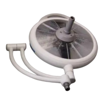
| 9 | DESCRIPTION S SERIES The S series surgical light (Standard Suspension) comprises the following : • Spacer tube (1). • Main arm (2) with balancing arm. • Coupola arm (3). • Type 4000 cupola (4). The S series comprises the following models: PRX 4001 S, 4401 S (ceiling-mounted), PRX 4002 S (wall-mounted), PRX 4003 S (mobile). - Page 10 | 10 | LA SERIE ACS The A.C.S. series (Automatic Compensated Suspension) comprises (Fig. 5.3): • A single, double or triple suspension com- prising one, two or three main arms (1). • One or two compensation units (4). • A balancing arm (2) when the light carries a 4000 satellite (3).
- Page 11 | 11 | CODING PRINCIPLE Codes used with PRISMALIX surgical lighting system: • The code for a surgical light model is formed as follows: • 3-letter symbol + 4 numbers + a combination of 3 to 8 letters • For example: PRX 6601 ACS / DF /CFF Interpretation: • Symbol: PRX (contraction of PRISMALIX) • Numbers...
-
Page 12: Acs Series
| 12 | CLASSIFICATION OF PRISMALIX CONFIGURATIONS BY FAMILY S SERIES SA SERIES ACS SERIES 6001 ACS/T 4001 S/DF/T 2001 6101 ACS/SUP 4001 S/SF/T 3001 SA 4002 S/DF/T 4001 SAI/DF/T 6201 ACS/T 4002 S/SF/T 4001 SAI/SF/T 6401 ACS/DF/CFF 4003 S/SF/T 4001 SAD/DF/T 6401 ACS/SF/CFF 6401 ACS/DF/VZ... -
Page 13: Technical Specifications
Low voltage consumption Voltage at bulb terminals (RMS) Number of MAQUET SA 23V/100W(***) 1 23V/100 W halogen bulbs *** Class 1 - type B (***) Bulbs specially designed for MAQUET SA. Prismalix | Technical manual | EN | 01132 | 04 |... - Page 14 | 14 | ELECTRICAL CONNECTIONS Connection from : to : Voltage Type of connection Electrical cabinet ENERGIX power 100/120 V or 3 x 2,5 mm2,per module 220/230 V module Electrical cabinet Cupola 23 Veff. ajustable Refer to NTR ENERGIX ref. 0612301 ENERGIX power module Control knob/pilot light...
-
Page 15: Technical Sheets Of Models
| 15 | TECHNICAL SHEETS OF MODELS 7.1.1 PRISMALIX 4001 S/DF/T 800 (31.5) 860 (33.9) Ø355 (14) Ø506 (20) Specifications Cupola 4000 Minimum height of room for clearance of 2717 2000 mm Position range of cupola 2045 Maximum reaction torque of the configuration m.DaN Weight (without suspension tube) 7.1.2... - Page 16 | 16 | 7.1.3 PRISMALIX 4001 SAX/DF 850 (33.5) 860 (33.9) Ø547 (21.6) Ø506 (20) Specifications Cupola 4000 Minimum height of room for clearance of 2591 2000 mm Position range of cupola 2095 Maximum reaction torque of the configuration m.DaN Weight (without suspension tube) 7.1.4 PRISMALIX 4002 S/SF...
- Page 17 | 17 | 7.1.5 PRISMALIX 4301 SA/DF 915 (36.1) 900 (35.5) 750 (29.6) 915 (36.1) Ø547 (21.6) Ø506 (20) Specifications Cupola 4000 Minimum height of room for clearance of 2825 2000 mm Position range of cupola 2169 Maximum reaction torque of the configuration m.DaN Weight (without suspension tube) 7.1.6...
- Page 18 | 18 | 7.1.7 PRISMALIX 4401 SAI DOUBLE FORK 915 (36.1) 900 (35.5) 750 (29.6) 915 (36.1) Ø547 (21.6) Ø506 (20) Ø506 (20) SINGLE FORK 872 (34.4) 900 (35.5) 750 (29.6) 852 (33.6) Ø547 (21.6) Ø506 (20) Ø506 (20) Specifications Cupola 4000 Cupola 4000 Minimum height of room for clearance of...
- Page 19 | 19 | 7.1.8 PRISMALIX 4401 SAX/SF 852 (33.6) 850 (33.5) 1000 (39.4) 852 (33.6) Ø547 (21.6) Ø506 (20) Ø506 (20) Specifications Cupola 4000 Cupola 4000 Minimum height of room for clearance of 2491 2000 mm Position range of cupola 2291 2441 Maximum reaction torque of the configuration...
- Page 20 | 20 | 7.1.10 PRISMALIX 4441 SAD/SF 872 (34.4) 1050 (41.4) 900 (35.5) 852 (33.6) 750 (29.6) Ø547 (21.6) Ø506 (20) Ø506 (20) Ø506 (20) 852 (33.6) Specifications Cupola Cupola Cupola 4000 4000 4000 Minimum height of room for clearance 2743 of 2000 mm Position range of cupola...
- Page 21 | 21 | 7.1.12 PRISMALIX 6201 SAL 1200 (47.3) 1350 (53.2) 1000 (39.4) Ø547 (21.6) 754 (29.7) Ø703 (27.7) Specifications Cupola 6000 Minimum height of room for clearance of 2000 mm 2971 Position range of cupola 2867 Maximum reaction torque of the configuration m.DaN (with 34 kg load) Weight...
- Page 22 | 22 | 7.1.14 PRISMALIX 6401 ACS DOUBLE FORK 190 (7.5) 950 (37.4) 1200 (47.3) 915 (36.1) Ø547 (21.6) 210° Ø703 (27.7) Ø506 (20) SINGLE FORK 190 (7.5) 950 (37.4) 1200 (47.3) 872 (34.4) Ø547 (21.6) 210° Ø506 (20) Ø703 (27.7) Specifications Cupola 6000 Cupola 4000...
- Page 23 | 23 | 7.1.15 PRISMALIX 6401 SA/SF 950 (37.4) 1200 (47.3) 872 (34.4) Ø547 (21.6) Ø506 (20) Ø703 (27.7) Specifications Cupola 6000 Cupola 4000 Minimum height of room for clearance of 2802 2000 mm Position range of cupola 2617 2660 Maximum reaction torque of the configura- m.DaN tion...
- Page 24 | 24 | 7.1.17 PRISMALIX 6411 SAL/DF 915 (36.1) 1200 (47.3) 1200 (47.3) 915 (36.1) 950 (37.4) Ø547 (21.6) Ø703 (27.7) Ø506 (20) 754 (29.7) Specifications Cupola 6000 Cupola 4000 Minimum height of room for clearance of 3034 2000 mm Position range of cupola 2617 2500...
- Page 25 | 25 | 7.1.19 PRISMALIX 6441 SA/SF 950 (37.4) 1200 (47.3) 872 (34.4) Ø547 (21.6) Ø506 (20) Ø703 (27.7) Specifications Cupola 6000 Cupola 4000 Cupola 4000 Minimum height of room for clea- 2934 rance of 2000 mm Position range of cupola 2617 2660 2660...
- Page 26 | 26 | 7.1.21 PRISMALIX 8421 ACS/DF 1000 (39.4) 1350 (53.2) 1200 (47.3) 915 (36.1) 190 (7.5) 950 (37.5) Ø547 (21.7) 210° Ø901 (35.5) Ø506 (20) Specifications Cupola 8000 Cupola 4000 Cupola 4000 Minimum height of room for clea- 3132 rance of 2000 mm Position range of cupola 2774...
- Page 27 | 27 | 7.1.23 PRISMALIX 2001 1350 (53.2) 1000 (39.4) Ø547 (21.6) Specifications 2001 Minimum height of room for clearance of 2000 mm 2868 Position range of cupola 2801 Maximum reaction torque of the configuration m.DaN (with 34 kg load) Weight (with 34 kg load) 7.1.24...
-
Page 28: Installation
| 28 | INSTALLATION INSTALLATION RECOMMENDATIONS Refer to the installation recommendations manual for the PRX surgical lighting systems Ref. 011363001. S SERIES INSTALLATION MANUAL Por installation of an S series surgical lighting system, refer to the installation manual for sim- plified suspensions Ref. -
Page 29: Cleaning / Disinfection / Sterilisation
Users must contact their hospital's sanitary specialists. The recommended products and procedures must be applied. Should there be any doubt concerning the compatibility of active agents to be used, contact the local Maquet customer service department. CLEANING AND DISINFECTING THE SURGICAL LIGHT RECOMMENDATION Check that the power is switched off and the light has cooled down before starting cleaning. -
Page 30: Cleaning And Sterilising The Handles
| 30 | CLEANING AND STERILISING THE HANDLES 9.2.1 BEFORE CLEANING Use a soft cloth immediately after use to wipe away soiling from the handle surface. Store handles in a place that keeps them moist to make further cleaning easier. Take care to store them in such a way that the inside does not get soiled. - Page 31 | 31 | 9.2.4 STERILISATION After cleaning, the handles must be steam sterilised as set out below: Countries Sterilisation Temperature Time Drying cycle [ °C ] [min] [ min ] USA & Canada Prevacuum 132 - 135 ATNC (Prion) France (Prevacuum) Other countries Prevacuum...
-
Page 32: General Maintenance
By a MAQUET technician or MAQUET-approved distributor during the guarantee period. By a MAQUET technician or MAQUET-approved distributor or by the hospital’s technical maintenance department outside the guarantee period (Contact your dealer to arrange the required technical training.) - Page 33 | 33 | Checks Check that the retaining ring is present and in the correct position on the lighthead spring arm. Check that spring ring is not worn and is in the correct position (remove and lubricate if necessary). Adjust the balance of the spring arm Adjust the vertical stop on the spring arm Check that all blanking plates are firmly attached to the spring arm.
- Page 34 | 34 | Checks Check the condition of the terminal block (not burnt) in the lighthead. Check the proper insertion of the female plugs on the male plugs. Check the condition of the complete electrical wiring. Tightening of the terminal block screws. Check that the lamp cover opens and closes correctly.
- Page 35 | 35 | Checks Check that the camera operates correctly (image and functions on VZ). Measure the earth bonding on all visible conductive metal parts with the earth bonding tester: R ≤ 0.1 Ohm Check that there are no sticky points when the main arm, ACS enclosure, spring arm and lighthead are moved.
- Page 36 | 36 | Checks Open the ENERGIX power supply enclosure and check that the connection terminal heads are tightly fastened. Turn on the lighthead. Simulate a power cut and check that the lighthead continues to operate, either on a UPS backup system or on batteries.
- Page 37 | 37 | Checks Check that the lighting is correctly configured on the control boards. Check that the battery module wires are tightly faste- ned. For PRX 4003, check that the casters are tightly faste- ned. For PRX 4003, the lamp must be vertical and stable. For PRX 4003, check the rotation of the spring arm.
-
Page 38: Remplacement De La Coupole
| 38 | 10.3 REMPLACEMENT DE LA COUPOLE 10.3.1 CLEANING THE 4000 CUPOLA: MPRX NO. 001 See drawing No.1 Before starting any repair operation, ensure the cupola has cooled down. The following operations can be performed with the cupola mounted on its arm . Cut off the circuit breaker situated upstream from output module. - Page 39 | 39 | 10.3.2 CHANGING PRISMS OF 4000 CUPOLA OR UNDERSIDE: MPRX NO. 002 See drawing No.1 The following repair operations are performed with the cupola mounted on its arm. Tools required: 4 mm Allen wrench, TORX 10 wrench, OPM No. 055, OPM No. 058. • Remove the sterilizable handle.
- Page 40 | 40 | 10.3.3 CLEANING THE 6000 CUPOLA: MPRX NO. 003 See drawing 2 The following repair operations can be performed with the cupola mounted on its arm. Tools required: 4 mm Allen wrench, 3 mm Allen wrench, 2.5 Allen wrench, flat tip screwdriver. • Secure the cupola in the low position using the transport screw.
- Page 41 | 41 | 10.3.4 REPLACING 6000 CUPOLA PRISMS OR UNDERSIDE: MPRX NO. 004 See drawing 2 The following repair operations can be performed with the cupola mounted on its arm. Tools required: 4 mm Allen wrenc, TORX 10 wrench, OPM No. 055, OPM No. 058. • Remove the 3 CHC screws (20) securing the lower cover (30) and remove the lower cover.
- Page 42 | 42 | • Clean the mirror and the intermediate athermal belt. • Clean the intermediate condenser (680). • Remove the 3 screws (650) and washers (660) and disassemble the lower part. • Clean the mirror and the lower athermal belt. • Clean the lower condenser (580);...
-
Page 43: Replacement Of Electrical Socket (410) On Closing Plate
| 43 | 10.4 REPLACEMENT OF ELECTRICAL SOCKET (410) ON CLOSING PLATE (380): MPRX NO. 007 See drawings 1, 2, ou 3 The following repair operations can be performed with the cupola mounted on its arm. Tools required: 4 mm Allen wrench, 3 mm Allen wrench. Secure the cupola in the low position using the lock or transport screw. -
Page 44: Replacing Rotating Contact On 6000 Cupola: Mprx No. 008
| 44 | 10.5 REPLACING ROTATING CONTACT ON 6000 CUPOLA: MPRX NO. 008 Drawings 7 and 2 Tools required: 3 mm Allen wrench, 4 mm Allen wrench, 3 mm Allen driver, 2.5 mm Allen driver, crimping pliers, stripping pliers, centering OPM for seal, Torx screwdriver No. 10, flat tip screwdriver. Cupola arm side: drawing 7A • Remove the screw (160) and cover (150). -
Page 45: Replacing Acs Cupola Arm: Mprx No. 010
| 45 | 10.7 REPLACING ACS CUPOLA ARM: MPRX NO. 010 Drawings 11 and 7 The female rotating contact (item 70, drawing 7A) of cupola arm cannot be repaired on site. Tools required: 3 mm Allen wrench, 4 mm Allen wrench. • Secure the compensation unit in the low position using the transport screw (160). -
Page 46: Replaciing Bearing Subassembly (505) On 6000 Or 8000 Cupola: Mprx No
| 46 | 10.10 REPLACING BEARING SUBASSEMBLY (505) ON 6000 OR 8000 CUPO- LA: MPRX NO. 013 Drawing 2 or 3 Tools required: 4 mm Allen wrench, flat tip screwdriver. Disassembly of cupola (drawing 7): • Secure the compensation unit in the low position using the transport screw (160, Drawing 11). -
Page 47: Replacing Brake On Main Arm, Compensation Unit Side: Mprx No
| 47 | 10.13 REPLACING BRAKE ON MAIN ARM, COMPENSATION UNIT SIDE: MPRX NO. 013 Drawing 13 Tools: 4 mm Allen wrench, flat tip screwdriver. RECOMMANDATION Disassemble the cupola, the cupola arm and the compensation unit referring to the installa- tion manual 011543001, chapters 6 to 8 • Loosen the brake adjustment screw (290). -
Page 48: Repair Kits And Subassemblies
| 48 | 10.16 REPAIR KITS AND SUBASSEMBLIES Description Quantity References MAQUET SA logo repair kit 3 672 01 555 MAQUET SA cupola label Arm and housing label Label 6000/8000 cupola band Cover and stop segment repair kit 3 672 02 555... - Page 49 | 49 | 10.17 RECOMMENDED SPARE PARTS AND CONSUMABLES Description Quantity References Kit with 10 halogen bulbs 23V/100W ECL 0001 3 672 02 038 Lamp support for 4000 cupola 3 672 02 489 Lamp support for 6000 cupola 3 672 02 488 Lamp support for 8000 cupola 3 672 02 487 1-liter can of antistatic cleaning product, ECL NET...
- Page 50 | 50 | PARTS LISTS AND DRAWINGS PARTS LIST 1 4000 CUPOLA Reference Description REF. 567236998 4000 cupola with SF arm 567236993 4000 cupola with DF arm 567202041 Sterilizable handle sleeve 567202257 Lower cover assembly 567202514 Tilt control S/A 567203998 NTSC camera S/A 567203996 PAL camera S/A...
- Page 51 | 51 | DRAWING 1 4000 CUPOLA Prismalix | Technical manual | EN | 01132 | 04 |...
- Page 52 | 52 | PARTS LIST 2 6000 CUPOLA Reference Description REF. 567237998 6000 cupola 567202041 Sterilisable handle sleeve 567202257 Equipped lower cover S/A 567202516 Tilt control S/A 145A 567240998 Equipped cover S/A, comprend (rep.150A, 160A, 170A et 180A) 210A 567202251 Hinge 225A 367202374...
- Page 53 | 53 | DRAWING 2 6000 CUPOLA Prismalix | Technical manual | EN | 01132 | 04 |...
- Page 54 | 54 | PARTS LIST 3 8000 CUPOLA Reference Description REF. 567238998 8000 cupola 567202041 Sterilisable handle sleeve 567202257 Equipped lower cover S/A 567202515 Tilt control S/A 145A 567240998 Equipped cover S/A comprising (items 150 A, 160A, 170A and 180A) 210A 567202251 Hinge...
- Page 55 | 55 | DRAWING 3 8000 CUPOLA Prismalix | Technical manual | EN | 01132 | 04 |...
- Page 56 | 56 | PARTS LIST 4 4000 SF CUPOLA ARM Reference Description REF. 567235998 4000 SF cupola arm 567202351 Stopper 567204998 Repair S/A Cable assembly, comprising (items 20A, 40A and 60A) 657700001 Lock screw 100A 567202048 Stop ring Prismalix | Technical manual | EN | 01132 | 04 |...
- Page 57 | 57 | DRAWING 4 4000 SF CUPOLA ARM VERSION VIDEO Prismalix | Technical manual | EN | 01132 | 04 |...
- Page 58 | 58 | PARTS LIST 5 4000 DF CUPOLA ARM Reference Description REF. 567234998 4000 DF cupola arm 110A 567202351 Stopper 145A 367203998 Repair S/A Cable assembly, comprising (items 120A and 140A) 160A 657700001 Lock screw 170A 567202048 Stop ring Prismalix | Technical manual | EN | 01132 | 04 |...
- Page 59 | 59 | DRAWING 5 4000 DF CUPOLA ARM Prismalix | Technical manual | EN | 01132 | 04 |...
- Page 60 | 60 | PARTS LIST 6 6000 SA CUPOLA SWIVEL ARM Reference Description REF. 567232996 6000 SA cupola swivel arm 367206998 Repair S/A Rotating contact, comprising (items 20A, 40A, 60A and 75A) 100A 567202351 Stopper Prismalix | Technical manual | EN | 01132 | 04 |...
- Page 61 | 61 | DRAWING 6 6000 SA CUPOLA SWIVEL ARM Prismalix | Technical manual | EN | 01132 | 04 |...
- Page 62 | 62 | PARTS LIST 7 ACS 6000/8000 CUPOLA ARM Reference Description REF. 567232998 ACS 6000 cupola 567233998 ACS 8000 cupola 567202351 End piece 567201263 Cupola arm handle 100A 600780616 Thin-head CHc screw M6x16 115A 367207998 Repair S/A Rotating contact, comprising (Items 110A, 130A and 70A) 180A 367201555...
- Page 63 | 63 | DRAWING 7 BRAS DE COUPOLE 6000/8000 ACS Prismalix | Technical manual | EN | 01132 | 04 |...
- Page 64 | 64 | PARTS LIST 8 4000 S CUPOLA BALANCING ARM Reference Description REF. 567214995 4000 S DF balancing arm 567207995 4000 S SF balancing arm 367208555 Repair S/A Rotating contact comprising (items 110A, 130A and 70A) 940000177 Arm cover (comprising items 190A and 200A) 367246555 End piece arm cover (comprising items 170A and 180A) 367202555...
- Page 65 | 65 | DRAWING 8 4000 S CUPOLA BALANCING ARM Prismalix | Technical manual | EN | 01132 | 04 |...
- Page 66 | 66 | PARTS LIST 9 BALANCING ARM, SA/ACS 4000 CUPOLA Reference Description REF. 567214995 4000 SA/ACS DF 367222995 Bushing (to order) 567211995 Video 4000 DF 567218995 4000 SA/ACS SF 567212995 Video 4000 SF 567008002 Brake 9204850 Reach adjustment cover 940000047 Bottom metal plate ref.
- Page 67 | 67 | DRAWING 9 BALANCING ARM, SA/ACS 4000 CUPOLA Prismalix | Technical manual | EN | 01132 | 04 |...
- Page 68 | 68 | PARTS LIST 10 6000 CUPOLA BALANCING ARM Reference Description REF. 567216995 6000 cupola balancing arm 367233555 Kit of spring arm lower inspection cover 367245555 Repair kit (Stop segment + cover) 367237555 Kit of 5 spring arm brakes 100A 567201084 Rotating contact wire bundle assembly...
- Page 69 | 69 | DRAWING 10 6000 CUPOLA BALANCING ARM Prismalix | Technical manual | EN | 01132 | 04 |...
- Page 70 | 70 | PARTS LIST 11 6000/8000 COMPENSATION UNIT Reference Description REF. 567230996 6000 cupola compensation 567231996 8000 cupola compensation 567230995 6000 video cupola 367202998 Dia. 50 brake repair S/A (comprising items 30A, 440A and 540A) 1 567201555 Logo S/A 160A 600560835 CHc screw, flat tip...
- Page 71 | 71 | DRAWING 11 6000/8000 COMPENSATION UNIT Prismalix | Technical manual | EN | 01132 | 04 |...
- Page 72 | 72 | PARTS LIST 12 SAI/SAD 4400 ARM Reference Description REF. 567266998 SAI 4400 arm 567288998 SAD 4400 arm 130A 567201045 7-track brush D50 150A 567203973 CFF camera power sply S/A 210A 567201102 4000 main arm cable assembly (male) 220A 639404502 Retaining ring T81 D50...
- Page 73 | 73 | DRAWING 12 BRAS 4400 SAI/SAD Prismalix | Technical manual | EN | 01132 | 04 |...
- Page 74 | 74 | PARTS LIST 13 SUPPORT SPRING ARM Reference Description REF. 567226995 Support spring arm 110A 688000005 Articulation mask 140A Stop segment 150A Segment mask Prismalix | Technical manual | EN | 01132 | 04 |...
- Page 75 | 75 | DRAWING 13 SUPPORT SPRING ARM Prismalix | Technical manual | EN | 01132 | 04 |...
- Page 76 | 76 | PARTS LIST 14 FLAT PANEL MONITOR HOLDER Reference Description REF. 567206001 Upper frame 567206002 Lower frame 625025202 Friction ring 567202351 Bumper 567203976 Sterilizable handle PRX 602980021 Spring washer 601860051 Notched nut 567206003 Flat panel cable* 622302503 Thin washer 567208001 Handle support 567206004...
- Page 77 | 77 | DRAWING 14 FLAT PANEL MONITOR HOLDER Prismalix | Technical manual | EN | 01132 | 04 |...
- Page 78 | 78 | PARTS LIST 15 SUPPORT MAIN ARM Reference Description REF. 567277994 Main arm 567201154 50mm dia. brake 250A 567226008 Cover (two parts) 260A 567226017 Shaft stop 340A 513601803 Set PMC brake 410A 567201011 Plug 420A 567226024 Stop label Prismalix | Technical manual | EN | 01132 | 04 |...
- Page 79 | 79 | DRAWING 15 SUPPORT MAIN ARM 200 190 Prismalix | Technical manual | EN | 01132 | 04 |...
- Page 80 | 80 | PARTS LIST 16 EQUIPMENT SUPPORT Reference Description REF. 567226994 Equipment support 567206001 Tray 567206002 Plastic washer 625025202 Plastic support 567202351 Washer 25 567203976 Handle Prismalix | Technical manual | EN | 01132 | 04 |...
- Page 81 | 81 | DRAWING 16 EQUIPMENT SUPPORT Prismalix | Technical manual | EN | 01132 | 04 |...
- Page 82 | 82 | PARTS LIST 17 S/A SINGLE MAIN ARM SAX Reference Description REF. 204820 Male contact fixation screw 204815 Male contact support 180362 Male contact 204823 Arm cable harness 204855 Spring arm brake 204862 Access plate fixation screw 204858 Washer 204826 Brush assy access plate...
- Page 83 | 83 | DRAWING 17 S/A SINGLE MAIN ARM SAX Prismalix | Technical manual | EN | 01132 | 04 |...
- Page 84 | 84 | PARTS LIST 18 S/A DOUBLE MAIN ARM SAX Reference Description REF. 204820 Male contact fixation screw 204815 Male contact support 180362 Male contact 204823 Outer arm cable harness 204855 Spring arm brake 204822 Center arm cable harness 204862 Access plate fixation screw 204858...
- Page 85 | 85 | DRAWING 18 S/A DOUBLE MAIN ARM SAX Prismalix | Technical manual | EN | 01132 | 04 |...
- Page 86 | 86 | PARTS LIST 19 S/A TRIPLE MAIN ARM SAX Reference Description REF. 204820 Male contact fixation screw 204815 Male contact support 180362 Male contact 204823 Outer arm cable harness 204855 Spring arm brake 204822 Center arm cable harness 204862 Access plate fixation screw 204858...
- Page 87 | 87 | DRAWING 19 S/A TRIPLE MAIN ARM SAX Prismalix | Technical manual | EN | 01132 | 04 |...
- Page 88 | 88 | PARTS LIST 20 6400 MAIN ARM Reference Description REF. 567264998 6400 main arm 130A 567201045 7-track brush D50 150A 567203991 CFF camera power sply S/A 190A 567203058 VD 4000 arm cable 220A 639404502 Retaining ring T81 D50 290A 367202998 50mm dia.
- Page 89 | 89 | DRAWING 20 6400 MAIN ARM Prismalix | Technical manual | EN | 01132 | 04 |...
- Page 90 | 90 | PARTS LIST 21 REINFORCED FLANGE Reference Description REF. 513899999 Anchoring plate (ECL 016) 567260998 Flange (ECL 2001) 567201348 Suspension tube à 567201361 568037999 Curved cover - 2 items (ECL 1011) 568038999 Flat cover - 2 items (ECL 1012) 567260999 Curved cover - 1 item (ECL 1013) 567260997...
- Page 91 | 91 | DRAWING 21 BRIDE RENFORCÉE Prismalix | Technical manual | EN | 01132 | 04 |...
- Page 92 | 92 | PARTS LIST 22 SUSPENSION FOR 4001 S DR. REF. Reference Description 567211111 Suspension arm for 4001 S, SF (See drawing 9) 567211211 Suspension arm for 4001 S, DF (see drawing 9) 10A à 120A 567203995 Spacer 130A à 150A 567205995 Main arm 160A à...
- Page 93 | 93 | DRAWING 22 SUSPENSION FOR 4001 S Prismalix | Technical manual | EN | 01132 | 04 |...
- Page 94 | 94 | PARTS LIST 23 SUSPENSION FOR 4401S DR. REF. Reference Description 567212111 Suspension arm for 4401S, SF (see drawing 9) 567212211 Suspension arm for 4401S, DF (see drawing 9) 10A, 80A, 130A, 140A 567219995 Spacer 90A, 100A, 150A 567206995 Main arm 180A,110A,120A, 210A 567214995...
- Page 95 | 95 | DRAWING 23 SUSPENSION FOR 4401S Prismalix | Technical manual | EN | 01132 | 04 |...
- Page 96 | 96 | PARTS LIST 24 SUSPENSION FOR 4002 SF OR DF DR. REF. Reference Description 567213111 Suspension arm for 4002 SF, S, (see drawing 9) 567213211 Suspension arm for 4002 DF, S, (see drawing 9 10A, 20A 567201995 Spacer 30A, 40A, 50A 567202995 Main arm...
- Page 97 | 97 | DRAWING 24 SUSPENSION FOR 4002 SF OR DF Prismalix | Technical manual | EN | 01132 | 04 |...
- Page 98 | 98 | Prismalix | Technical manual | EN | 01132 | 04 |...
- Page 99 May be corrected on short term. Taking out of service is recommended. Remarks ..................................................................................................................................Signature Name: ..............Name: ..............Date: ..............Function: .............. Installer/Technician authorized by MAQUET Customer Prismalix | Technical manual | EN | 01132 | 04 |...
- Page 100 | 100 | Measuring equipment used Type: Voltmeter S/N: ......Calibration valid until: ......IEC 62353 compatible control units Type: Luxmeter S/N: ......Calibration valid until: ......Type: Megohmeter S/N: ......Calibration valid until: ......Type: ....S/N: ......Calibration valid until: ......Electrical safety test The protective earth resistance is to be measured between point and the point...
- Page 101 | 101 | Installation Delivery verification Delivery complies with Purchase Order Installation manual included User manual included Visual inspection Rotating contact and circlips General aspect and cleaness ...
- Page 102 | 102 | Place sub-assembly stickers here Please remove the identification sticker from the packaging and place it in one of the below window frame. Cupola 1 with S/N Cupola 2 with S/N Cupola 3 with S/N Note: if applicable, please staple the delivery note with this docu- ment.
- Page 103 S/N : .......... Replacement of : ........... S/N : .......... Replacement of : ........... S/N : .......... Maquet batteries replaced Remarks .................................................................................................................................... Illumination verification → Minimum value : 40 000 lux, maximum value allowed : 160 000 lux ...
- Page 104 | 104 | Settings Balance of the spring arm Vertical stop of the spring arm Test the equipment is easy to handle. Checkings Hardness of the suspension by shaking the configuration Verticality of the suspension tube ...
- Page 105 | 105 | Tightening Collar around the power supply connector at the ceiling tube Wires on the power supply connector at the ceiling tube Ceiling covers + proper positioning Wires on the connectors’ terminal heads inside the WPS ...
- Page 106 | 106 | Prismalix | Technical manual | EN | 01132 | 04 |...
- Page 107 | 107 | RETURN THIS COPY CHECKLIST TO YOUR MAQUET DISTRIBUTOR SERVICE PROTOCOL For use during Installation / Servicing Prismalix Contract Order n°....... Chargeable Other:............ Installation Delivery date: ..... Installation date: ....... Commissioning date: .........
- Page 108 | 108 | Measuring equipment used Type: Voltmeter S/N: ......Calibration valid until: ......IEC 62353 compatible control units Type: Luxmeter S/N: ......Calibration valid until: ......Type: Megohmeter S/N: ......Calibration valid until: ......Type: ....S/N: ......Calibration valid until: ......Electrical safety test The protective earth resistance is to be measured between point and the point...
- Page 109 | 109 | Installation Delivery verification Delivery complies with Purchase Order Installation manual included User manual included Visual inspection Rotating contact and circlips General aspect and cleaness ...
- Page 110 | 110 | Place sub-assembly stickers here Please remove the identification sticker from the packaging and place it in one of the below window frame. Cupola 1 with S/N Cupola 2 with S/N Cupola 3 with S/N Note: if applicable, please staple the delivery note with this docu- ment.
- Page 111 S/N : .......... Replacement of : ........... S/N : .......... Replacement of : ........... S/N : .......... Maquet batteries replaced Remarks .................................................................................................................................... Illumination verification → Minimum value : 40 000 lux, maximum value allowed : 160 000 lux ...
- Page 112 | 112 | Settings Balance of the spring arm Vertical stop of the spring arm Test the equipment is easy to handle. Checkings Hardness of the suspension by shaking the configuration Verticality of the suspension tube ...
- Page 113 | 113 | Tightening Collar around the power supply connector at the ceiling tube Wires on the power supply connector at the ceiling tube Ceiling covers + proper positioning Wires on the connectors’ terminal heads inside the WPS ...
- Page 114 | 114 | SAFETY PARTS TO BE REPLACED EVERY 6 YEARS Safety screws: Maquet recommends replacing the safety screws every six years as a precaution. TUBES BUSHINGS ADAPTERS SA suspension arm cap TUB 60 ADPT 120 TO 60 ARD515088999 SUSP. BLUE 30-80 SUSP.
- Page 115 | 115 | Prismalix | Technical manual | EN | 01132 | 04 |...
- Page 116 DVT prevention, medical beds, therapeutic surfaces and diagnostics, Getinge for For your local contact: infection control and prevention within Healthcare and Life Science Please visit our website and Maquet for Surgical Workplaces, Cardiovascular and Critical www.maquet.com Care. Prismalix | Technical manual...
Need help?
Do you have a question about the Prismalix 4000 and is the answer not in the manual?
Questions and answers