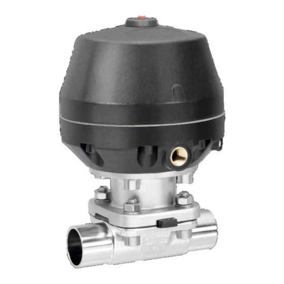
GEM 650 Special function J Operating Instructions Manual
Pneumatically operated diaphragm valve
Hide thumbs
Also See for 650 Special function J:
- Installation, operating and maintenance instructions (44 pages) ,
- Installation, operating and maintenance instruction (52 pages) ,
- Operating instructions manual (136 pages)

Related Manuals for GEM 650 Special function J


Summary of Contents for GEM 650 Special function J
- Page 1 GEMÜ 650 / 687 Special function J Pneumatically operated diaphragm valve Operating instructions Special function J...
- Page 2 All rights including copyrights or industrial property rights are expressly reserved. Keep the document for future reference. © GEMÜ Gebr. Müller Apparatebau GmbH & Co. KG 11.10.2023 GEMÜ 650 / 687 Special function 2 / 52 www.gemu-group.com...
-
Page 3: Table Of Contents
15.4 Stroke limiter ..........4 Description ............16 Commissioning ............ 650 BioStar, special function J version ....17 Operation ............. 5 GEMÜ 650 product description ......18 Troubleshooting ..........Design ............Description ............. 19 Inspection and maintenance ........ Function ............ -
Page 4: General Information
Symbol Meaning 1.3 Definition of terms Danger of explosion! Working medium The medium that flows through the GEMÜ product. Control function Corrosive chemicals! The possible actuation functions of the GEMÜ product. Control medium The medium whose increasing or decreasing pressure causes Hot plant components! the GEMÜ... -
Page 5: Safety Information
Prior to commissioning: 1. Transport and store the product correctly. The GEMÜ 650 and 687 2/2-way diaphragm valve with special function J is suitable for operating pressures of up to 16 bar. 2. Do not paint the bolts and plastic parts of the product. -
Page 6: Biostar, Special Function J Version
Description The GEMÜ 650 BioStar 2/2-way diaphragm valve has a stainless steel piston actuator and is pneumatically operated. The valve is designed for use in a sterile environment. All actuator parts are made from stainless steel (except seals). It is available with a... -
Page 7: Gemü 650 Product Description
(see Conexo informa- data (example): tion) The month of manufacture is encoded in the traceability num- CONEXO actuator RFID ber and can be obtained from GEMÜ. The product was manu- chip factured in Germany. (see Conexo informa- tion) 5.2 Description The GEMÜ... -
Page 8: Order Data
90° offset to flow direction Flange ANSI Class 125/150 RF, Actuator size 3TA face-to-face dimension FTF EN 558 series 1, ISO 5752, basic series 1, length only for body configuration D GEMÜ 650 / 687 Special function 8 / 52 www.gemu-group.com... -
Page 9: Order Example
Only for types 650 and 687 Only for diaphragm sizes 10 to 50 Only for forged bodies and block material bodies Only for seal code 5M Only with special actuator 11 CONEXO Without www.gemu-group.com 9 / 52 GEMÜ 650 / 687 Special function... -
Page 10: Technical Data
PTFE diaphragms exposed to high temperature fluctuations. The maintenance cycles must be adapted accordingly. GEMÜ 555 and 505 globe valves are particularly suitable for use in the area of steam generation and distribution. The following valve arrangement for interfaces between steam pipes and process pipes has proven itself over time: A globe valve for shutting off steam pipes and a diaphragm valve as an interface to the process pipes. -
Page 11: Pressure
Therefore the Kv values may exceed the tolerance limits of the stand- ard. The Kv value curve (Kv value dependent on valve stroke) can vary depending on the diaphragm material and dur- ation of use. www.gemu-group.com 11 / 52 GEMÜ 650 / 687 Special func- tion J... -
Page 12: Product Compliance
HFT (Hardware Fault Tolerance): 0 MTTR (Mean Time To Restora- 24 hours tion): Product description: GEMÜ diaphragm valve 650_687with GEMÜ 032x pilot solenoid valve Device type: Fail safe function: Due to the fail safe function, the diaphragm valve is placed in the closed position (with control function 1). -
Page 13: Dimensions
G 1/4 M16x1 32, 40 3TA, 3RA 223.0 52.0 144.0 G 1/4 M16x1 Dimensions in mm, MG = diaphragm size * CT = A + H1 (see body dimensions) www.gemu-group.com 13 / 52 GEMÜ 650 / 687 Special func- tion J... -
Page 14: Body Dimensions
Code 60: Spigot ISO 1127/DIN EN 10357 series C (2014 edition)/DIN 11866 series B 2) Valve body material Code 40: 1.4435 (F316L), forged body Code 42: 1.4435 (BN2), forged body, Δ Fe < 0.5% Code F4: 1.4539, forged body GEMÜ 650 / 687 Special function 14 / 52 www.gemu-group.com... - Page 15 Code 65: Spigot ANSI/ASME B36.19M schedule 40s 2) Valve body material Code 40: 1.4435 (F316L), forged body Code 42: 1.4435 (BN2), forged body, Δ Fe < 0.5% Code F4: 1.4539, forged body www.gemu-group.com 15 / 52 GEMÜ 650 / 687 Special func- tion J...
- Page 16 Code 37: Spigot SMS 3008 2) Valve body material Code 40: 1.4435 (F316L), forged body Code 42: 1.4435 (BN2), forged body, Δ Fe < 0.5% Code F4: 1.4539, forged body GEMÜ 650 / 687 Special function 16 / 52 www.gemu-group.com...
- Page 17 1) Connection type Code 6: Threaded spigot DIN 11851 2) Valve body material Code 40: 1.4435 (F316L), forged body Code 42: 1.4435 (BN2), forged body, Δ Fe < 0.5% www.gemu-group.com 17 / 52 GEMÜ 650 / 687 Special func- tion J...
- Page 18 1) Connection type Code 6K: Cone spigot and union nut DIN 11851 2) Valve body material Code 40: 1.4435 (F316L), forged body Code 42: 1.4435 (BN2), forged body, Δ Fe < 0.5% GEMÜ 650 / 687 Special function 18 / 52 www.gemu-group.com...
- Page 19 Code 8: Flange EN 1092, PN 16, form B, face-to-face dimension FTF EN 558 series 1, ISO 5752, basic series 1, length only for body configur- ation D 2) Valve body material Code 40: 1.4435 (F316L), forged body Code 42: 1.4435 (BN2), forged body, Δ Fe < 0.5% www.gemu-group.com 19 / 52 GEMÜ 650 / 687 Special func- tion J...
- Page 20 Code 39: Flange ANSI Class 125/150 RF, face-to-face dimension FTF EN 558 series 1, ISO 5752, basic series 1, length only for body config- uration D 2) Valve body material Code 40: 1.4435 (F316L), forged body Code 42: 1.4435 (BN2), forged body, Δ Fe < 0.5% GEMÜ 650 / 687 Special function 20 / 52 www.gemu-group.com...
- Page 21 Code 8T: Clamp DIN 32676 series C, face-to-face dimension FTF EN 558 series 7, length only for body configuration D 2) Valve body material Code 40: 1.4435 (F316L), forged body Code 42: 1.4435 (BN2), forged body, Δ Fe < 0.5% Code F4: 1.4539, forged body www.gemu-group.com 21 / 52 GEMÜ 650 / 687 Special func- tion J...
- Page 22 Code 8E: Clamp ISO 2852 for pipe ISO 2037, clamp SMS 3017 for pipe SMS 3008, face-to-face dimension FTF EN 558 series 7, length only for body configuration D 2) Valve body material Code 40: 1.4435 (F316L), forged body Code 42: 1.4435 (BN2), forged body, Δ Fe < 0.5% Code F4: 1.4539, forged body GEMÜ 650 / 687 Special function 22 / 52 www.gemu-group.com...
-
Page 23: Special Function J Version
- Wide range of adaptation options for add-on components and accessories Description The GEMÜ 687 2/2-way diaphragm valve has a low-maintenance plastic membrane actuator and is pneumatically operated. The valve has a metal distance piece. It is available with a "Normally Closed (NC)" control function. -
Page 24: Gemü 687 Product Description
(example): CONEXO body RFID chip The month of manufacture is encoded in the traceability num- (see Conexo informa- ber and can be obtained from GEMÜ. The product was manu- tion) factured in Germany. CONEXO actuator RFID chip (see Conexo informa- tion) 9.2 Description... -
Page 25: Order Data
DIN 11866 H5, basic series 1, mechanically polished internal, length only for body configuration D *) for inner pipe diameters < 6 mm, in the spigot Ra ≤ 0.38 μm www.gemu-group.com 25 / 52 GEMÜ 650 / 687 Special function... -
Page 26: Order Example
Only for types 650 and 687 Only for diaphragm sizes 10 to 50 Only for forged bodies and block material bodies Only for seal code 5M Only with special actuator 11 CONEXO Without GEMÜ 650 / 687 Special function 26 / 52 www.gemu-group.com... -
Page 27: Technical Data
PTFE diaphragms exposed to high temperature fluctuations. The maintenance cycles must be adapted accordingly. GEMÜ 555 and 505 globe valves are particularly suitable for use in the area of steam generation and distribution. The following valve arrangement for interfaces between steam pipes and process pipes has proven itself over time: A globe valve for shutting off steam pipes and a diaphragm valve as an interface to the process pipes. - Page 28 Therefore the Kv values may exceed the tolerance limits of the stand- ard. The Kv value curve (Kv value dependent on valve stroke) can vary depending on the diaphragm material and dur- ation of use. GEMÜ 650 / 687 Special function 28 / 52 www.gemu-group.com...
-
Page 29: Mechanical Data
(with control function 1). HFT (Hardware Fault Tolerance): MTTR (Mean Time To Restoration): 24 hours Product description: GEMÜ diaphragm valve 650_687with GEMÜ 032x pilot solen- oid valve Device type: Fail safe function: Due to the fail safe function, the diaphragm valve is placed in the closed position (with control function 1). -
Page 30: Dimensions
170.0 59.0 G 1/4 171.0 208.0 75.0 G 1/4 211.0 244.0 90.0 G 1/4 Dimensions in mm MG = diaphragm size * CT = A + H1 (see body dimensions) GEMÜ 650 / 687 Special function 30 / 52 www.gemu-group.com... -
Page 31: Body Dimensions
Code 60: Spigot ISO 1127/DIN EN 10357 series C (2014 edition)/DIN 11866 series B 2) Valve body material Code 40: 1.4435 (F316L), forged body Code 42: 1.4435 (BN2), forged body, Δ Fe < 0.5% Code F4: 1.4539, forged body www.gemu-group.com 31 / 52 GEMÜ 650 / 687 Special func- tion J... - Page 32 Code 65: Spigot ANSI/ASME B36.19M schedule 40s 2) Valve body material Code 40: 1.4435 (F316L), forged body Code 42: 1.4435 (BN2), forged body, Δ Fe < 0.5% Code F4: 1.4539, forged body GEMÜ 650 / 687 Special function 32 / 52 www.gemu-group.com...
- Page 33 Code 37: Spigot SMS 3008 2) Valve body material Code 40: 1.4435 (F316L), forged body Code 42: 1.4435 (BN2), forged body, Δ Fe < 0.5% Code F4: 1.4539, forged body www.gemu-group.com 33 / 52 GEMÜ 650 / 687 Special func- tion J...
- Page 34 MG = diaphragm size 1) Connection type Code 6: Threaded spigot DIN 11851 2) Valve body material Code 40: 1.4435 (F316L), forged body Code 42: 1.4435 (BN2), forged body, Δ Fe < 0.5% GEMÜ 650 / 687 Special function 34 / 52 www.gemu-group.com...
- Page 35 Code 6K: Cone spigot and union nut DIN 11851 2) Valve body material Code 40: 1.4435 (F316L), forged body Code 42: 1.4435 (BN2), forged body, Δ Fe < 0.5% www.gemu-group.com 35 / 52 GEMÜ 650 / 687 Special func- tion J...
- Page 36 Code 8: Flange EN 1092, PN 16, form B, face-to-face dimension FTF EN 558 series 1, ISO 5752, basic series 1, length only for body configur- ation D 2) Valve body material Code 40: 1.4435 (F316L), forged body Code 42: 1.4435 (BN2), forged body, Δ Fe < 0.5% GEMÜ 650 / 687 Special function 36 / 52 www.gemu-group.com...
- Page 37 Code 39: Flange ANSI Class 125/150 RF, face-to-face dimension FTF EN 558 series 1, ISO 5752, basic series 1, length only for body config- uration D 2) Valve body material Code 40: 1.4435 (F316L), forged body Code 42: 1.4435 (BN2), forged body, Δ Fe < 0.5% www.gemu-group.com 37 / 52 GEMÜ 650 / 687 Special func- tion J...
- Page 38 Dimensions in mm MG = diaphragm size 1) Valve body material Code 40: 1.4435 (F316L), forged body Code 42: 1.4435 (BN2), forged body, Δ Fe < 0.5% Code F4: 1.4539, forged body GEMÜ 650 / 687 Special function 38 / 52 www.gemu-group.com...
- Page 39 MG = diaphragm size 1) Valve body material Code 40: 1.4435 (F316L), forged body Code 42: 1.4435 (BN2), forged body, Δ Fe < 0.5% Code F4: 1.4539, forged body www.gemu-group.com 39 / 52 GEMÜ 650 / 687 Special func- tion J...
-
Page 40: Manufacturer's Information
▶ Risk of burns Only work on plant that has cooled 4. Do not store solvents, chemicals, acids, fuels or similar ● down. fluids in the same room as GEMÜ products and their spare parts. CAUTION 13.4 Delivery Exceeding the maximum permissible pressure. -
Page 41: Installation Position
6. Reassemble the valve body and the actuator with dia- Fig. 4: Flanged connection phragm (see "Mounting the actuator" chapter). 7. Re-attach or reactivate all safety and protective devices. 8. Flush the system. www.gemu-group.com 41 / 52 GEMÜ 650 / 687 Special function... -
Page 42: After The Installation
8. Use all flange holes. 9. Re-attach or reactivate all safety and protective devices. Connector 2 10. Tighten the bolts diagonally. 14.7 After the installation ● Re-attach or reactivate all safety and protective devices. GEMÜ 650 / 687 Special function 42 / 52 www.gemu-group.com... -
Page 43: Connecting The Control Medium
2. Flush the piping system of new plant and following repair NOTICE work (the product must be fully open). ▶ For GEMÜ 687, there must not be a stroke limiter fitted. ð Harmful foreign matter has been removed. ð The product is ready for use. -
Page 44: Troubleshooting
Threaded connections / unions loose Tighten threaded connections / unions Sealing material faulty Replace sealing material Valve body leaking Valve body leaking or corroded Check valve body for damage, replace valve body if necessary GEMÜ 650 / 687 Special function 44 / 52 www.gemu-group.com... -
Page 45: Inspection And Maintenance
CAUTION Servicing and maintenance work must only be performed ● by trained personnel. Do not extend hand lever. GEMÜ shall assume no liability ● whatsoever for damages caused by improper handling or third-party actions. In case of doubt, contact GEMÜ prior to commissioning. -
Page 46: Spare Parts For The 687
2. Clean all parts of remains of product and contaminants. Do not scratch or damage parts during cleaning. 3. Check all parts for potential damage. 4. Replace damaged parts (only use genuine parts from GEMÜ). GEMÜ 650 / 687 Special function 46 / 52 www.gemu-group.com... - Page 47 Place the compressor loosely on the actuator spindle, fit the recesses D into the guides C and A into B. It must be possible to move the compressor freely between the guides. www.gemu-group.com 47 / 52 GEMÜ 650 / 687 Special function...
- Page 48 The compressor is loose on diaphragm sizes 25–50 (DN 15– 1. Move the actuator A to the closed position. 65). 2. GEMÜ 650: Diaphragm sizes 10, 40, Diaphragm size 25–50 (DN 15–65): GEMÜ 687: Diaphragm sizes 25, 40, 50 Place the compressor loosely on the actuator spindle, fit Compressor and actuator flange seen from below: the recesses D into the guides C.
-
Page 49: Removal From Piping
If 1. Move the actuator A to the open position. no return delivery note is included with the product, GEMÜ 2. Position the actuator A with the mounted diaphragm 2 on cannot process credits or repair work but will dispose of the the valve body 1. -
Page 50: Eu Declaration Of Incorporation According To The Ec Machinery Directive 2006/42/Ec, Annex Ii B
EC Machinery Directive 2006/42/EC, Annex II B Machinery Directive introductory text We, the company GEMÜ Gebr. Müller Apparatebau GmbH & Co. KG Fritz-Müller-Strasse 6–8 74653 Ingelfingen-Criesbach, Germany hereby declare under our sole responsibility that the below-mentioned product complies with the relevant essential health and safety requirements in accordance with Annex I of the above-mentioned Directive. -
Page 51: Eu Declaration Of Conformity In Accordance With 2014/68/Eu (Pressure Equipment Directive)
Information for products with a nominal size ≤ DN 25: The products are developed and produced according to GEMÜ's in-house process instructions and standards of quality which comply with the requirements of ISO 9001 and ISO 14001. According to Article 4, Paragraph 3 of the Pressure Equipment Direct- ive 2014/68/EU, these products must not be identified by a CE-marking. - Page 52 GEMÜ Gebr. Müller Apparatebau GmbH & Co. KG Fritz-Müller-Straße 6-8, 74653 Ingelfingen-Criesbach, Germany Subject to alteration Phone +49 (0) 7940 1230 · info@gemue.de www.gemu-group.com 10.2023 | 88887281...
Need help?
Do you have a question about the 650 Special function J and is the answer not in the manual?
Questions and answers