
Related Manuals for Soler & Palau TRCeN500/V


Summary of Contents for Soler & Palau TRCeN500/V
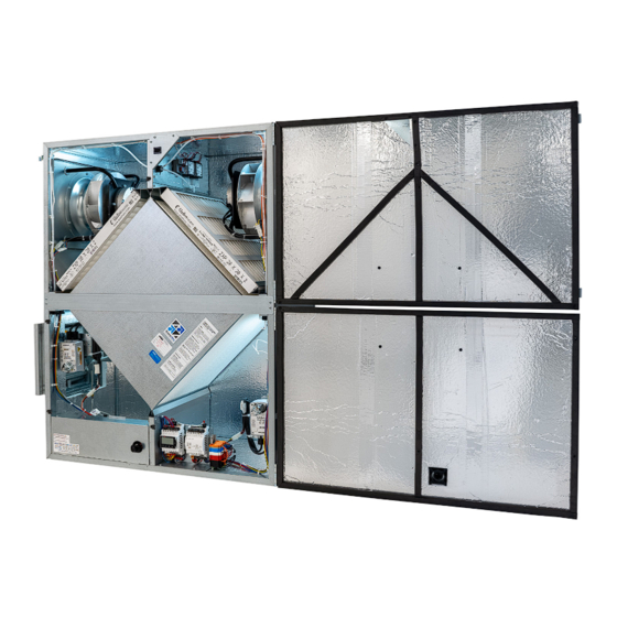
- Page 1 INSTALLATION, OPERATION & MAINTENANCE MANUAL ENERGY RECOVERY VENTILATOR TRCeN500/V TRCeN800/V Model: TRCeN800V shown...
- Page 2 TRCeN-Series WARNING AVERTISSEMENT Les moteurs EC (ECM) ne conviennent PAS pour une EC motors (ECM) are NOT suitable for use with solid state utilisation avec un contrôle de vitesse à semi-conducteurs. speed control. They already have speed control built into the motor electronics.
- Page 3 OWNER INFORMATION TRCeN-Series READ AND SAVE THIS MANUAL/LIRE ET CONSERVER CE MANUEL NOTICE NOTE: This unit is an Energy Recovery This manual contains space for maintaining written records of unit maintenance and/ Ventilator, or ERV. or repairs. See Section 7.7 Maintenance Records. At the time the ERV is commissioned, a It is commonly referred to maintenance schedule should be developed by the user to incorporate monthly and seasonal throughout this manual as...
-
Page 4: Table Of Contents
6.2.6 Inspect and Clean the Cabinet Interior .......20 3.1 UNIT WEIGHTS AND DIMENSIONS ......8 6.2.7 Inspect Ductwork Connections ..........20 3.1.1 TRCeN500/V Unit Dimensions and Weight: ......8 6.3 UNIT START UP .............20 3.1.2 TRCeN500/V Maximum Shipping Dimensions and Weight..8 6.3.1 Starting Up ECM Units............20 3.1.3 TRCeN800/V Unit Dimensions and Weight: ......8... - Page 5 Figure 6.4.1 Initial Pressure Drop of MERV 8 Filters, Supplied with TRCeN500/V ........ 22 Figure 6.4.2 Initial Pressure Drop of MERV 13 Filters, Available as a TRCeN500/V Accessory ..... 22 Figure 6.4.3 Initial Pressure Drop of MERV 8 Filters, Supplied with TRCeN800/V ........ 23 Figure 6.4.4 Initial Pressure Drop of MERV 13 Filters, Available as a TRCeN800/V Accessory .....
-
Page 6: Overview
OVERVIEW TRCeN-Series 1.0 OVERVIEW 1.1 DESCRIPTION The TRCeN-Series Energy Recovery Ventilator (ERV) is a device for recovering both sensible energy (heat) and latent energy (moisture) from the Exhaust Air from an Occupied Space and injecting those energies into an incoming Outside Air stream. It accomplishes this task by forcing the two airstreams through enthalpic cores, where the energy exchange takes place. -
Page 7: Component Descriptions
COMPONENT DESCRIPTIONS TRCeN-Series 2.0 COMPONENT DESCRIPTIONS 2.1 CABINET The cabinet for the TRCeN-Series is made of 20 gauge galvanized steel and has 1" thick high- density, foil-backed insulation on the inside. Units are available in either single-wall or double- wall construction. Doors are hinged and are fitted with stainless steel machine screws through the faces to prevent accidental opening of the doors when the unit is in operation. -
Page 8: Filters
TRCeN-Series 2.5 FILTERS All TRCeN500/V units come equipped with two MERV 8 14" x 20" x 2" (nominal) pleated filters. All TRCeN800/V units come equipped with two MERV 8 20" x 20" x 2" (nominal) pleated filters. MERV 13 filters can be ordered as an accessory and are shipped loose. -
Page 9: Rigging And Center Of Gravity
SHIPPING/RECEIVING TRCeN-Series 3.2 RIGGING AND CENTER OF GRAVITY 3.2.1 TRCeN-Series Hoisting Weights and COG Spreader bars and straps are recommended in order to avoid damage to the unit. BASIC UNIT WEIGHTS (lbs.) Motors UNIT Standard (1P/208-230V) Intermediate (1P/208-230V) Advanced (1P/115V) 36.45 (W) Advanced (1P/208-230V) ADDITIONAL WEIGHTS FOR OPTIONS (lbs.) -
Page 10: Receiving
SHIPPING/RECEIVING TRCeN-Series BASIC UNIT WEIGHTS (lbs.) Motors UNIT Standard (1P/208-230V) Advanced (1P/115V) 36.46 (W) Advanced (1P/208-230V) Advanced (3P/460V) ADDITIONAL WEIGHTS FOR OPTIONS (lbs.) Options UNIT Double Wall 21.5 21.5 21.5 21.5 Bypass RA or EA Damper OA or FA Damper 20.49 (A) Total Selected Weights INDICATES LOCATIONS AT WHICH CORNER WEIGHTS ARE... -
Page 11: Storage
UNIT PLACEMENT TRCeN-Series 3.4 STORAGE Units that must be stored prior to installation should be left on their pallets and protected from weather and physical damage. Units must be placed on a level surface to prevent wracking of the pallet and the TRCeN. All access doors must be secured with all available hardware (door latches and securing bolts) and all openings into the cabinet must be sealed to prevent entry of dust, dirt and debris. -
Page 12: Figure 4.2.1 Trcen500V Service Clearances, Top View
UNIT PLACEMENT TRCeN-Series 17 1/2" Overall Door Swing 36 1/2" Minimum Service Area FIGURE 4.2.1 TRCeN500V SERVICE CLEARANCES, TOP VIEW TOP VIEW 15 7/8" Pressure 23 3/4" Case Ports (4) T 1 1/4" Duct Overall 12"x12" Duct Flanges, 37 5/8" Case 1 7/8", Typ. -
Page 13: Sound Attenuation
INSTALLATION TRCeN-Series 4.3 SOUND ATTENUATION Take these simple steps to attenuate noise from the unit. 4.3.1 Ducts Make sure the ductwork at the unit outlets is stiff enough to resist the flexure and resulting booming associated with system start up and shut off, as well as the turbulent flow conditions at the impeller outlets. -
Page 14: Floor Installation
INSTALLATION TRCeN-Series 5.2 FLOOR INSTALLATION Most units are installed in a location specified by others. In general, it’s preferable to install the NOTE: To prevent unit on a flat, reasonably level surface, such as a concrete floor. The factory-installed leveling the entry of rain legs are to be used to level the unit before connecting ductwork. -
Page 15: Hanging Bracket Kit
INSTALLATION TRCeN-Series 5.3.3 Hanging Bracket Kit The TRCeN-Series ERV can also be mounted to structural members using the Hanging Bracket Kit, available as an accessory. Remove the four adjustable legs and use the included 3/8"-16 bolts and washers to attach the hanging brackets to the unit as shown in Figure 5.3.1. The hanging brackets may be attached directly to a structural member or used in combination with threaded rod and the hanging vibration isolators described in section 5.3.2. -
Page 16: Factory-Recommended Electric Service Entry
INSTALLATION TRCeN-Series 5.4.1 Factory-Recommended Electric Service Entry NOTE: Your unit is The TRCeN-Series has an internal E-box in the lower left corner of the unit. 7/8" knockouts equipped with EC are provided on the sides and bottom of the unit for high-voltage power and low-voltage Motors (ECM). -
Page 17: How To Reset The 24Vac Circuit Breaker
INSTALLATION TRCeN-Series CAUTION 1. Connect only to components intended for use with 24VAC power. NOTICE 2. Do not undersize the low-voltage wires connected to this device. Observe the wire length If primary-side voltage and gauge limits indicated in this manual. is 230VAC, move black primary-side lead from 3. -
Page 18: Wiring Schematics
INSTALLATION TRCeN-Series 5.5 WIRING SCHEMATICS FIGURE 5.5.0 TRCeN-SERIES WIRING DIAGRAM WWW.SOLERPALAU-USA.COM INSTALLATION, OPERATION AND MAINTENANCE MANUAL 1.800.961.7370... -
Page 19: External Control Connections
N(L-) 0-10 V N(L-) INSTALLATION TRCeN-Series 5.6 EXTERNAL CONTROL CONNECTIONS NOTE: The sim- plified schematics below show only the relevant portions of the 24VAC 24VAC low-voltage control circuit in the ERV unit and 24VAC DOORKILL1 DOORKILL1 24VAC 24VAC representational external 24VAC DOORKILL1 24VAC... -
Page 20: Operation
OPERATION TRCeN-Series 6.0 OPERATION 6.1 PRINCIPLE OF OPERATION The TRCeN-Series ERV has one basic purpose: to exhaust air from a structure and bring in SA from outside, while transferring heating or cooling energy from the EA to the SA. The TRCeN-Series ERV is a very simple device, and will accomplish this purpose as long as the impeller is able to move air through the enthalpic core. -
Page 21: Balancing Airflow
OPERATION TRCeN-Series IMPORTANT It is important to balance the airflows after the unit is operational and all ductwork has been installed. Balancing the airflows is typically required by state and/or local codes, and is often specified by the HVAC design engineer. NOTE: ERV airflows Optimum efficiency of the enthalpic cores is achieved when the airstreams are properly balanced. -
Page 22: Filter Pressure Drop
FIGURE 6.4.1 INITIAL PRESSURE DROP OF MERV 8 FILTERS, SUPPLIED WITH TRCeN500/V Initial Pressure Drop of MERV 13 Filters (available option) Unit Airflow (CFM) FIGURE 6.4.2 INITIAL PRESSURE DROP OF MERV 13 FILTERS, AVAILABLE AS A TRCeN500/V ACCESSORY WWW.SOLERPALAU-USA.COM INSTALLATION, OPERATION AND MAINTENANCE MANUAL 1.800.961.7370... -
Page 23: Normal Operation
OPERATION TRCeN-Series Initial Pressure Drop of MERV 8 Filters supplied with this unit NOTE: Clean filter pressure drop is in- cluded in unit airflow D_APR16 20x20x2 MERV 13 (IOM) performance tables. 1000 Unit Airflow (CFM) Initial Pressure Drop of MERV 13 Filters FIGURE 6.4.3 INITIAL PRESSURE DROP OF MERV 8 FILTERS, SUPPLIED WITH TRCeN800/V (available option) 1000... -
Page 24: Operation In Extreme Cold Weather
MAINTENANCE TRCeN-Series 6.6 OPERATION IN EXTREME COLD WEATHER TRCeN-Series units are capable of operating without internal frosting at temperatures down to -10°F, with indoor humidity below 40%. The units can operate under more severe conditions occasionally with little or no impact on their performance. At lower humidities, they can operate at still lower outside temperatures without freezing the enthalpic cores. -
Page 25: Enthalpic Core
MAINTENANCE TRCeN-Series 7.6 ENTHALPIC CORE CAUTION RISK OF DAMAGE TO ENTHALPIC CORES Whenever working within the ERV cabinet, protect the enthalpic cores from accidental damage. The core media is subject to damage from dropped tools or other foreign objects. 7.6.1 Enthalpic Core Maintenance The enthalpic core media is a fibrous material that must be kept clean at all times. -
Page 26: Service Parts
MAINTENANCE TRCeN-Series 7.8 SERVICE PARTS FIGURE 7.8.0 TRCeN500/V SERVICE PARTS WWW.SOLERPALAU-USA.COM INSTALLATION, OPERATION AND MAINTENANCE MANUAL 1.800.961.7370... -
Page 27: Troubleshooting
FACTORY ASSISTANCE TRCeN-Series FIGURE 7.8.1 TRCeN800/V SERVICE PARTS 8.0 TROUBLESHOOTING If problems occur with a Soler & Palau ERV, the primary resources for troubleshooting are the unit as-built wiring schematics and the Sequence Of Operation (SOO) for each control scheme. WWW.SOLERPALAU-USA.COM INSTALLATION, OPERATION AND MAINTENANCE MANUAL 1.800.961.7370... - Page 28 (800) 961-7370 FAX: (800) 961-7379 6393 POWERS AVE JACKSONVILLE, FLORIDA 32217 USA WWW.SOLERPALAU-USA.COM CANADA (416) 744-1217 FAX: (416) 744-0887 6710 MARITZ DRIVE, UNIT 7 MISSISSAUGA, ON L5W 0A1, CANADA WWW.SOLERPALAUCANADA.COM 147640_000 (11/23)
Need help?
Do you have a question about the TRCeN500/V and is the answer not in the manual?
Questions and answers