Table of Contents
Advertisement
Quick Links
Advertisement
Table of Contents

Related Manuals for truflo UltraFlo 500 Series


Summary of Contents for truflo UltraFlo 500 Series
- Page 1 UltraFlo ® 500 Series Clamp-On Ultrasonic Flow Meter UltraFlo 500 Series ® Clamp-On Ultrasonic Flow Meter Operating Manual Read the user's manual carefully before starting to use the unit. Producer reserves the right to implement changes without prior notice.
-
Page 2: Table Of Contents
UltraFlo ® 500 Series Clamp-On Ultrasonic Flow Meter Table of Contents Safety Information Product Description Features Exploded View Working Principle Technical Specifications Components Installation and Connection Panel Function Keypad Functions Powering ON Display Description Setup Menu Pipe Parameter Setup Menu System Setting Setup Menu Calibration Setup Menu Output Setting Setup Menu... -
Page 3: Safety Information
The manufacturer reserves the right to revise, alter, or modify the flow meter to the most current technology without special prior notice. Further information about the latest updates and potential additions to these operating instructions are available from Truflo. Product Description... -
Page 4: Features
UltraFlo ® 500 Series Clamp-On Ultrasonic Flow Meter Features Pipe Sizes ½ to 4" Under 2 Minute Installation Time No Contact with Liquid No Moving Parts Simple to Install-No Cutting of Pipe 4-20mA | RS485 Output Flow Rate + Totalizer | Resettable Simple Programming Large Blue OLED Low Light Display Wide Dynamic Flow Range... -
Page 5: Working Principle
UltraFlo ® 500 Series Clamp-On Ultrasonic Flow Meter Working Principle M12 Quick Connection Upper Bracket Sensor Body Flow Flow Lower Bracket Signal B Signal A Technical Specifications General Accuracy 2.0% Repeatability 0.8% Data Storage Day, Month and Year Flow Totalizer Response Time Analog Output 4 ~20mA... -
Page 6: Components
UltraFlo ® 500 Series Clamp-On Ultrasonic Flow Meter Components Sensor Body Upper Bracket Lower Bracket M12 Cable Installation and Connection Display Upper Bracket Lower Bracket Screw Pipe Align the Upper Bracket to the pipe position. Magnets will hold brackets in place. Make sure no dirt, paint, or other Using the mounting screws connect the stains on the surface of the tube. -
Page 7: Panel Function
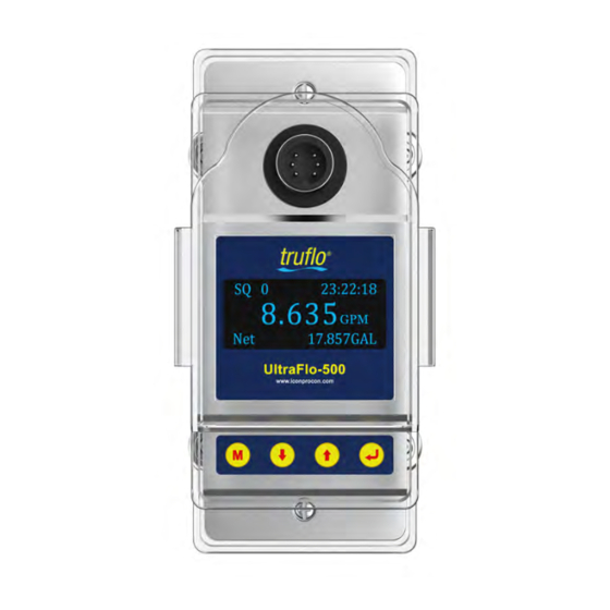
UltraFlo ® 500 Series Clamp-On Ultrasonic Flow Meter Panel Function Mounting Screw M12 Connector Flow Rate 23:22:18 SQ 0 Bright LCD Display 8.635 723.58 GAL Net Totalizer UltraFlo-500 www.iconprocon.com Keypad Mounting Screw Keypad Functions Follow these Guide Lines when using the Flow Meter Keypad: Press to Enter the Programming Mode or to return to the previous menu during programming. -
Page 8: Display Description
UltraFlo ® 500 Series Clamp-On Ultrasonic Flow Meter Display Description STEPS DISPLAY OPERATION SQ 99 12:30:18 When power is on, the flow meter will display Flow Rate / Net Totalizer. Main Display 3.368 Signal quality & Time. 768.89 GAL Press Runtime 216h Press... -
Page 9: Pipe Parameter Setup Menu
UltraFlo ® 500 Series Clamp-On Ultrasonic Flow Meter Pipe Parameter Setup Menu STEPS DISPLAY OPERATION Press to display Setup menu. Setup menu The following options are available (using the buttons) 0. Pipe parameter Setup menu 1. System setting 0. Pipe Parameter 2. - Page 10 UltraFlo ® 500 Series Clamp-On Ultrasonic Flow Meter STEPS DISPLAY OPERATION Previous Page 5. System lock System setting 0. System Unit System lock System Unlocked ENT key word System lock 1. Flow Rate Unit System Unlocked ENT to lock 0000 System locked OK System Setting 2.
-
Page 11: Calibration Setup Menu
UltraFlo ® 500 Series Clamp-On Ultrasonic Flow Meter Calibration Setup Menu STEPS DISPLAY OPERATION to display Setup Menu. Press Setup menu The following options are available (using the buttons) 0. Pipe parameter Setup Menu 0. Pipe parameter 1. System setting 1. -
Page 12: Output Setting Setup Menu
UltraFlo ® 500 Series Clamp-On Ultrasonic Flow Meter Generally, pipes made of SS304 or SS316 are with wall thickness of Previous Page more than 2mm. In practical use, it will receive false signals due to Calibration the interference of pipe wall signals, It is recommended that the low 0. - Page 13 UltraFlo ® 500 Series Clamp-On Ultrasonic Flow Meter STEPS DISPLAY OPERATION 2. Alarm Value (Optional) Previous Page Output setting Alarm value 0. RS485 Setup 0. Low value 1. 4-20mA range Output Setting 1. High value 2. Alarm value Enter the low alarm value; any measured flow lower than the low value, 3.
-
Page 14: Data Logging Setup Menu
UltraFlo ® 500 Series Clamp-On Ultrasonic Flow Meter Data Logging Setup Menu STEPS DISPLAY OPERATION Press to display Setup menu. Setup menu The following options are available (using the buttons) 0. Pipe parameter 0. Pipe parameter 1. System setting Setup Menu 1. -
Page 15: Warranty, Returns & Limitations
1) There is evidence of a potentially hazardous material present with the product; 2) The product has remained unclaimed at Truflo for more than 30 days after Icon Process Controls has dutifully requested disposition. This warranty contains the sole express warranty made by Truflo in connection with its products. ALL IMPLIED WARRANTIES, INCLUDING WITHOUT LIMITATION, THE WARRANTIES OF MERCHANTABILITY AND FITNESS FOR A PARTICULARPURPOSE, ARE EXPRESSLY DISCLAIMED.
Need help?
Do you have a question about the UltraFlo 500 Series and is the answer not in the manual?
Questions and answers