
Subscribe to Our Youtube Channel
Related Manuals for Still MX-X


Summary of Contents for Still MX-X
- Page 1 Original instructions Order picking truck MX-X 2332 2334 5231 804 2502 EN - 04/2020...
-
Page 3: Table Of Contents
Table of contents Foreword General ............EC declaration of conformity . - Page 4 Table of contents Overview Industrial-truck view ........... Standard design of labelling .
- Page 5 Table of contents Driving ............. Braking, driving and steering .
- Page 6 Table of contents Optispeed versions ........... Split operating panel .
- Page 7 Table of contents Mounting system for auxiliary components ....... . . USB charging station .
- Page 9 Foreword...
-
Page 10: Foreword General
Foreword General General Our industrial trucks comply with applicable European regulations. Any other applicable country-specific regulations or operating con- ditions for the use of industrial trucks must al- so be observed. The aim of this manual is to inform you about how to safely handle your industrial truck and how to keep it operational. -
Page 11: Ec Declaration Of Conformity
Foreword EC declaration of conformity EC declaration of conformity Declaration STILL GmbH Berzeliusstraße 10 D-22113 Hamburg Germany We declare that the Industrial truck according to these operating instructions Model according to these operating instructions conforms to the most recent version of EC Machinery Directive 2006/42/EC and the most re- cent version of EMC Directive 2014/30/EU for industrial trucks implemented in accordance with harmonised standard EN 12895:2015. -
Page 12: Safety Instructions
Foreword Safety instructions Safety instructions Explanations of the terms used in this manual: DANGER There is the risk of fatality to the operator. The procedures indicated should be complied with in full in order to avoid this danger. WARNING There is a hazard that could cause major damage to property or to the health of the operator. -
Page 13: Truck Identification, Factory Nameplate
Foreword Truck identification, Factory nameplate Truck identification, Factory nameplate The nameplate is fitted in the area of the driv- ing seat and contains the following details: Factory nameplate CE symbol. The CE symbol confirms that Nominal loading capacity the EU machine guidelines and all the rele- Unladen weight vant guidelines, which are valid for this prod- Battery voltage... -
Page 14: Product Documentation
Foreword Product documentation Product documentation This includes: Spare parts list ● Operating and maintenance manual ● Any additional documentation for the driv- ● er's seat Any additional documentation for an attach- ● ment Any additional documentation for the bat- ●... -
Page 15: Safe-Keeping And Passing On
Internet address and QR code The information can be accessed at any time by pasting the address https://m.still.de/vdma in a web browser or by scanning the QR code. Safe-keeping and passing on These operating and maintenance instruc- ●... -
Page 16: Copyright And Proprietary Rights
Foreword Copyright and proprietary rights Copyright and proprietary rights This manual - and any excerpts thereof - may not be reproduced, translated or tansmitted in any form to third parties without the express written permission of the manufacturer. 5231 804 2502 EN - 04/2020... -
Page 17: Operator, Form Of Address
Foreword Operator, Form of address Operator, Form of address Our products are suitable for use by male or If these industrial trucks are operated by per- female operators. However, these instructions sons who do not meet the criteria specified in use only the masculine form of address, here- EN ISO 3411, the following effects must be inafter "operator", to simplify the text. - Page 18 Foreword Operator, Form of address 5231 804 2502 EN - 04/2020...
-
Page 19: Safety
Safety... -
Page 20: Working Safely
Safety Working safely Working safely The industrial truck must be operated exclu- Safe working environment ● sively from the driver's compartment People must not encroach into the working ● If industrial trucks are equipped for pedes- ● area (danger area) of the industrial truck; If trian mode or with external operating pan- a person does enter the danger area, all els, the industrial trucks may be operated... -
Page 21: Vibrations
Safety Vibrations Vibrations The vibrations of the machine must be deter- Tests have indicated that the amplitude of the mined on an identical machine in accordance hand and arm vibrations on the steering wheel with the EN 13059 standard "Vibration meas- or on the operating devices in the truck is less urements on industrial trucks". -
Page 22: Special Safety Information About Load Pick Up
Safety Special safety information about load pick up Special safety information about load pick up Recognising danger is half the battle! Before every load pick up, make sure that ● the load to be picked up does not exceed the load capacity of the truck (refer to the load capacity diagram) or the maximum permissible dimensions as specified on the... -
Page 23: Safe Handling Of Operating Media
Safety Safe handling of operating media Safe handling of operating media The following operating media are used in this truck: Gear oill ● Hydraulic oil ● Battery acid ● The handling of these materials is governed by comprehensive safety regulations. The most important points include: For gear and hydraulic oil DANGER... - Page 24 DANGER Danger of explosion – When charging batteries, an explosive gas mix- ture can be generated which can still remain present for a long period after completion of the charging process. Ensure adequate ventilation. – Within a 2 metre area of charged batteries, smok- ing, fires and open flames are strictly prohibited.
-
Page 25: Risk Assessment
Safety Risk assessment Risk assessment Within the scope of validity of the CE guide- lines, the operating company must create op- erating instructions on the basis of a risk as- sessment. The purpose of the risk assess- ment is to identify dangers and the associated risks that could occur due to the product or the application of the product in the specific place of use and under the application conditions at... -
Page 26: Application Area
Safety Application area may be necessary for another test to be car- ried out. The operating company is responsible for checking whether the country in which this in- dustrial truck is used requires regular safety checks to be carried out on the industrial truck by a specialist. -
Page 27: Narrow Aisle Vehicles
Safety Narrow aisle vehicles WARNING Restrictions in the applicational area. The industrial trucks described here must not be used: – in areas at risk from fire – in areas at risk from explosions – iin areas with atmospheres conducive to corrosion –... -
Page 28: Directives And Guidelines
Safety Directives and guidelines caused by the use of non-original parts and accessories. Directives and guidelines In most countries, the national directives and guidelines for proper usage of these trucks must be observed. We therefore ask you to please contact the relevant authorities or speak to the authorised representatives for more information. -
Page 29: Personal Protective Equipment
Safety Personal protective equipment well as in operating manuals and workshop manuals Mount a durable and easily visible label on ● the industrial truck providing details of the type of alteration or conversion, alteration or conversion date and name and address of the organisation entrusted with this task Personal protective equip- ment... - Page 30 Safety Personal protective equipment 5231 804 2502 EN - 04/2020...
-
Page 31: Overview
Overview... -
Page 32: Industrial-Truck View
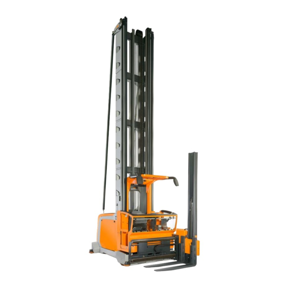
Overview Industrial-truck view Industrial-truck view (1) Overhead guard (2) Operating panel (3) Auxiliary lift mast (4) Load forks (5) Load wheel (6) Front guide rollers (7) Rear guide roller and support screws (8) Battery compartment or battery compart- ment doors* (9) Barrier or cab doors* (10) Control compartment (11) Portable lamp*... -
Page 33: Standard Design Of Labelling
Overview Standard design of labelling Standard design of labelling Danger! High voltage c. It is not permitted for people to sit or stand Foot switch on the load, on the load support, underneath a. Do not transport people on the load or on a raised load or to be carried as passengers. - Page 34 Overview Standard design of labelling Lifting point for crane loading Risk of crushing feet The container is under hydraulic pressure, Disconnect the battery male connector be- hydraulic cylinder. fore removing the control compartment Storage space for the abseil system hood. (Only for the 80-V version) A number of information signs are fitted on ev- ery industrial truck depending on the family to draw attention to hazards, technical data or re-...
-
Page 35: Labelling For Special Equipment
Overview Labelling for special equipment Labelling for special equipment It is not permitted for people to sit or stand Seat heater on/off switch on the load or the load support, or to be car- Switch in "switched off" position ried as passengers Switch in "switched on"... - Page 36 Overview Labelling for special equipment Truck with customised software. Only the standard software may be installed in the customer's special version and not the truck control unit. The pictograms shown here replace the picto- grams for the standard version or are fitted in addition to the standard pictograms.
-
Page 37: Intended Use
Overview Intended use Intended use The order picker truck is designed for narrow aisle operation. It permits pallets to be entered into and removed from storage, as well as or- der picking from the rack compartments. Observe the instructions in the paragraph "safety". -
Page 38: Operating Panel
Overview Operating panel order picking work. The auxiliary lift must al- ways remain in the lowest position when trav- elling. Outside the aisles (transfer aisle), the industri- al trucks can be driven freely with the load lowered (transportation mode). The load must be lifted only sufficiently high (clear of the ground) that no part of the load touches the ground. - Page 39 Overview Operating panel (3) Enable button (e.g. for releasing the brake (15) Selection key for lifting or lowering the in an automatic braking system or as bridging cab lift and auxiliary lift together, in connection for the intermediate lift cut-out and for ac- with pulling or pushing the operating lever (1), knowledging errors that can be acknowl- or the selection key for swivelling the fork syn-...
-
Page 40: Displays
Overview Displays Displays Emergency off switch pressed Not used Foot switch required *MPSE in operation Two-hand operation on the left re- *MPSE has detected a fault quired Two-hand operation on the right re- Not used quired Barrier open *Navigation, combination operation *Navigation, destination is located on the PIN entry expected left-hand side... -
Page 41: Operating The Display
Overview Operating the display Operating the display NOTE To emphasise the functionality, the following images have been simplified. Display in the operating panel Display in the case of split operation Function Operating statuses and information relevant for operation are shown on the display. Using the display, it may be possible to switch func- tions on and off or to switch between defined statuses. - Page 42 Overview Operating the display Half of the display can be occupied by a mes- sage window (1). This window is automatically inserted from the right-hand side. The informa- tion which was previously displayed centrally is then shown in the left-hand section of the display.
- Page 43 Overview Operating the display Left field Centre field Right field Configure favourites Truck settings Lift height preselection Approach lift heights Enter lift heights Clear lift heights Service Message list Top status bar The status bar at the top of the display is divi- ded into three fields: Left field (1) ●...
- Page 44 Overview Operating the display Procedure – Push button (7). The menu in area (1) opens. – Press key sequence (6), (3) and (5). – Select the status bar field using button (2), (3) or (4). – In the list, use buttons (2) to (6) to select the desired information.
- Page 45 Overview Operating the display Changes the view to the main page with the menu shown in the right-hand menu bar. If a settings page is displayed, the current setting can be saved. The function of membrane keys (1) to (10) is ...
- Page 46 Overview Operating the display Scrolling through the menu bar If an arrow appears in area (1) or (2), then the list contains additional entries. The arrow keys (3) can be used to scroll through the menu. If there is no longer an arrow in area (1), the start of the list has been reached.
- Page 47 Overview Operating the display Procedure – Push button (7). The menu in area (1) opens. – Press key sequence (6) and (4). – Use buttons (1)(10) to select the position for the favourite function. – Select the desired function in the list using buttons (6) to (10).
-
Page 48: Operating Instructions
Overview Operating instructions Brightness setting The brightness is automatically adjusted by a light sensor (1) below the display. NOTE For the automatic brightness feature to func- tion correctly, the sensor must not be covered or contaminated. Operating instructions The controller assists the operator in operating the industrial truck effectively. -
Page 49: Swivel Shift Fork
Overview Swivel shift fork Swivel shift fork The movements of the turret head are auto- matically braked before the turret head rea- ches its mechanical stop. The end positions are signalled to the controller by switches. The industrial truck drives at the maximum speed approved for the lift height only if the turret head is located in the right or left end position. - Page 50 Overview Other attachments Additional operating instructions and mainte- nance instructions from our suppliers may also apply. *Option 5231 804 2502 EN - 04/2020...
-
Page 51: Operation
Operation... -
Page 52: General Commissioning
Operation General commissioning General commissioning Initial commissioning NOTE Observe the section entitled Safe handling of consumables . Prior to initial commissioning, make sure that the entire industrial truck is properly assem- bled. All electrical and hydraulic connections must be checked. Mechanical connections that were removed for transportation must be reconnected with particular care. - Page 53 Operation General commissioning Delivery in units Specified weights apply only to the standard design. Determine or request the weights of special designs. Narrow aisle trucks can be disassembled into the following units: attachment, driver's cab in- cluding carriage, lift mast, battery and chassis. When assemblies comprised of multiple com- plete units are transported, the weights of the individual units must be added together so...
-
Page 54: Transporting And Loading
Operation General commissioning Overall mast height Weight <6 m <3,500 kg >6 m <4,300 kg Weight of the battery The weight of the battery is specified on the nameplate on the battery. NOTE The installed battery must as a minimum weigh the value stipulated on the nameplate on the truck. - Page 55 Operation General commissioning Hooking on the lift mast To hook the lift mast onto the crane hook, use the bores intended for this purpose at the top end of the lift mast (1). Harnesses suitable for this purpose must be used (shackle or lifting device).
- Page 56 Operation General commissioning Hooking the lift mast on horizontally If the lift mast needs to be crane-loaded in a horizontal position (2), suitable shackles must be used in the indicated bores at the top end of the mast (3). 5231 804 2502 EN - 04/2020...
- Page 57 Operation General commissioning Lift mast, lower lifting point At the lower end, a textile strap can be wound around the middle crosspiece in the beam support of the cab (4). Loading the chassis Electronic elements such as sensors and an- tennas can be installed at different places in the chassis according to the truck design.
- Page 58 Operation General commissioning Transportation safety device on glass doors Cab doors made of glass* are supplied with a transportation safety device. This transporta- tion safety device prevents the glass doors from inadvertently opening during transporta- tion and becoming damaged as a result. –...
-
Page 59: Support Screws
Operation General commissioning Wheel nuts WARNING Wheel nuts can loosen after initial commissioning. After the first eight operating hours, tighten the wheel nuts to 210 Nm. Support screws The setting of the support screws must be checked during initial commissioning and each time maintenance is performed. -
Page 60: Safe Handling Of The Traction Battery
Operation General commissioning Safe handling of the traction battery The dangers described below can arise indi- vidually or collectively depending on the type of battery in use. Batteries with liquid electrolyte DANGER Risk of explosion – An explosive gas mixture can form when charging batteries. - Page 61 Operation General commissioning 80-V version WARNING In the 80-V version, there is risk of electric shock if the live connections are touched. Before removing the control compartment cover or the battery compartment cover, disconnect the bat- tery male connector. Handling the battery The installation, removal and transport of trac- tion batteries always involves the handling of...
-
Page 62: Battery Compartment Cover, Service Flap
Operation General commissioning Battery compartment cover, Service flap The battery compartment cover covers the en- tire battery compartment. The cover is held by four clamping holders. The cover can be removed by applying light pressure from underneath near the corners. NOTE As an option, the industrial truck can be equip- ped with lateral battery compartment doors. - Page 63 Operation General commissioning updated. These narrow aisle trucks are equip- ped with an integrated battery discharge indi- cator that is set for normal wet lead batteries (PzS) as standard. If a different battery type or different battery capacity is used, the author- ised service partner must adapt the battery discharge indicator.
-
Page 64: Permitted Batteries
Operation General commissioning Commissioning If your industrial truck is equipped with a Euro battery male connector, make sure that the voltage index pin is in the correct position. The set voltage can be read through a display win- dow (1). WARNING Risk of accident Risk of injury from crushing zone and shearing zone... -
Page 65: Replacing The Battery
Operation General commissioning battery or if it was supplied with a dry pre- charged battery because it had to be transpor- ted over a long distance (e.g. from overseas). Observe the information and guidelines from the battery manufacturer. If the battery was obtained separately to the industrial truck, the nominal voltage, the required minimum weight and the attached battery male connector must... -
Page 66: Function Checking
Operation General commissioning Battery replacement with change frame The industrial truck can be optionally equipped with roller channels so that the battery can be replaced using a crane or battery change frame. When using a battery change frame, observe the corresponding operating instructions for the change frame. -
Page 67: Daily Commissioning
Operation Daily commissioning Daily commissioning Checklist before starting work Before starting work, the driver must make – Check that all the operating devices are op- sure that the truck is in a safe operating con- erating correctly. dition. Checking the access control –... - Page 68 Operation Daily commissioning – Make sure that when the barrier or cab – Check the function of the lighting devices. door* is open neither the traction nor any – Check that all covers and flaps are closed. hydraulic function can be activated. –...
-
Page 69: Driver's Compartment
Operation Driver's compartment Driver's compartment Access to the driver's compartment Barriers DANGER Risk of crushing Only the area of the handle indicated must be used for opening and closing the barriers. WARNING Risk of falling When climbing in and out, it is important to note the difference in height between the floor of the driver's compartment and the ground. - Page 70 Operation Driver's compartment Doors DANGER Risk of crushing Only the area of the handle indicated may be used to open and close the glass door. WARNING Risk of falling When climbing in and out, it is important to note the difference in height between the floor of the driver's compartment and the ground.
-
Page 71: Operating Devices
Operation Operating devices Operating devices Initial driving exercises WARNING Before starting work, the Checklist before starting work must be completed. Observe all safety instructions. WARNING Risk of accident In order to become familiarised with the driving and braking characteristics of these trucks, driving exerci- ses must first be carried out in a flat, obstacle-free area of the warehouse. -
Page 72: Adjusting The Position Of The Operating Panel
Operation Operating devices Adjusting the position of the operat- ing panel WARNING The clamping device that is released for the settings described below must be retightened before starting work. In order to be able to optimally adapt the oper- ating panel to driver requirements, the panel can be adjusted by height, by tilting the con- sole and by tilting the operating panel. -
Page 73: Driver's Seat
Operation Operating devices Driver's seat NOTE In addition to the standard driver's seat, sever- al other models are available as options. The corresponding original operating instructions from the manufacturer are supplied with each model. Observe these operating instructions. WARNING Risk of accident Only apply settings in a stationary truck. - Page 74 Operation Operating devices design and operation. Observe the original op- erating instructions supplied. Optional versions Folding armrests ● Heatable ● 80 mm longitudinal adjustment ● Lumbar support ● Air suspension ● Leather upholstery ● 5231 804 2502 EN - 04/2020...
-
Page 75: Switching On
Operation Switching on Switching on Switching on the controller Battery male connector To plug in the battery male connector, open the service flap behind the lift mast. Get into the cab and close the barriers/cab doors. NOTE Barriers/cab doors are monitored by monitor- ing switches to ensure that they are complete- ly and correctly closed. - Page 76 Operation Switching on Emergency off switch, key switch Unlock the emergency off switch by turning it clockwise. Switch on the key switch or activate the elec- tronic access control*. If the truck is in an error-free state, the indica- tor for normal operation appears on the opera- tion status display (see "Operating status dis- play").
- Page 77 Operation Switching on Electronic access control There is also the option to have these industri- al trucks equipped with electronic access con- trol (PIN code, RFID chip, magnetic card sys- tem). See the section entitled "Special equip- ment". 5231 804 2502 EN - 04/2020...
-
Page 78: Driving
The ancillary movements can only be used when the industrial truck is at a stand- still and the foot switch is not actuated. Braking Releasing the foot switch while driving triggers the electrical reverse current braking. - Page 79 Operation Driving Driving The drive direction and the driving speed are selected using the right-hand operating lever. Move the operating lever in the direction of the fork (2) until the required driving speed in the fork direction has been reached. Move the operating lever in the direction of the lift mast (3) until the required driving speed in the direction of the lift mast has been reached.
- Page 80 Operation Driving Two-hand driving operation Operation of the industrial truck with two hands is required within the aisles once the controller has detected the corresponding sen- sor system. To drive, you also need to touch the sensor surface on the left-hand end of the operating panel (5) with your left hand.
-
Page 81: Types Of Guidance
Operation Driving Driving and auxiliary lift In order to execute the two functions driving and auxiliary lift simultaneously, both operat- ing levers must be moved accordingly. Press the button (10) to select the auxiliary lift. The degree of activation is always infinitely variable. -
Page 82: Mechanical Guidance Mzf
Operation Driving More detailed information can be found in the relevant dedicated chapter. Inductive guidance (IZF)* The industrial trucks can be guided inductively when travelling within aisles. To achieve this, a wire is embedded into the floor; this wire is live with current. - Page 83 Operation Driving aisle detection recognises the location of truck and re-enables the steering. Changing the aisle If the industrial truck needs to be driven out of one aisle and into another, the following notes must be observed: – Drive the industrial truck completely out of the aisle.
-
Page 84: Load Pick Up
NOTE This combined hydraulic function can still be combined with the driving function. To do this, move the right-hand operating lever as well. 5231 804 2502 EN - 04/2020... - Page 85 Operation Load pick up Ancillary movements All movements of the load apart from the main lift are categorised as ancillary movements. Standard functions are: Sliding the fork. ● Swivelling the fork. ● Lifting the auxiliary lift. ● Touch the right-hand sensor surface(4) and move the left-hand operating lever in the di- rection (5) or (6) to trigger the reach move- ment to the left or right.
- Page 86 Operation Load pick up Swivelling and sliding the swivel fork 90° synchronously This function moves the turret head to the front position through a synchronised move- ment involving shifting and swivelling. This means that the swivelling function automati- cally stops at a swivel angle of 90 and the sideshift automatically stops in a central posi- tion in front of the cab.
- Page 87 Operation Load pick up Underside of the operating panel On the top of the operating panel, there are four buttons on the right-hand end that are op- erated using the thumb on your right hand. There are also four buttons (18) and (19) on the underside of the operating panel.
-
Page 88: Load Capacity Diagram
Operation Load pick up Load capacity diagram Depending on the job, a load capacity diagram may be generated and mounted in the cab. To ensure that the stability of the industrial truck is not jeopardised in any way, the load capaci- ty diagram and the load capacity restrictions specified on this diagram for certain applica- tion conditions must be observed. -
Page 89: Fork Arms, Adjustable
Operation Load pick up Fork arms, adjustable The standard design features forged fork arms that are manually adjustable. This allows dif- ferent pallets and load supports with suitable dimensions to be picked up. As an option, these industrial trucks can also be equipped with hydraulically adjustable fork arms. -
Page 90: Emergency Operation
Operation Emergency operation Emergency operation Emergency lowering via the operat- ing panel In certain circumstances, the truck control unit prevents further lowering of the cab. (chain breakage or slack chain situation, or faults with chain monitoring, faulty height measuring system, faulty rev sensor on the pump motor). - Page 91 Operation Emergency operation Removing the control compartment hood DANGER Danger of electric shock (80-V version) Disconnect the battery male connector before removing the control compart- ment hood. – Open the two screw plugs (1). – Hold the hood at the ventilation openings (2), lift it off and then place it to one side.
- Page 92 Operation Emergency operation DANGER Risk of physical injury If the emergency lowering function has to be used because the operator has fallen unconscious, make sure that all parts of the operator’s body are fully within the driver's cab so that there is therefore no risk he may be injured during the lowering procedure.
-
Page 93: Securing The Load Support
Operation Emergency operation Securing the load support In order to secure the load support against lowering during maintenance work, the lower- ing movement can be locked by closing the shut-off valves. A notch in the block section in- dicates the valve position. The notch is pointing in the direction of the ●... - Page 94 Operation Emergency operation Removing the control compartment hood DANGER Danger of electric shock (80-V version) Before the control compartment hood is removed, the battery male connector must be disconnected. – Rotate the two screw plugs (1) in a clock- wise direction and remove them.
- Page 95 * Option Towing with operational steering If the steering of the industrial truck is still op- erational, once the brake has been released the industrial truck can be towed either with a rope or with the tow bar.
- Page 96 Operation Emergency operation Towing with non-operational steering WARNING Emergency steering movements may be carried out only when the truck is at a standstill. Make sure that the industrial truck is switched off. These industrial trucks are equipped with a mechanical emergency steering device.
- Page 97 Operation Emergency operation Attachment points (5) for towing with the drive unit leading, (6) for towing with the fork leading 5231 804 2502 EN - 04/2020...
-
Page 98: Emergency Abseil System
Operation Emergency operation Emergency abseil system Exiting the raised driver's compartment in the event of an emergency NOTE An emergency abseil system is only required if the driver's compartment can be raised higher than 3000 mm above the ground. NOTE Two versions are available. - Page 99 Operation Emergency operation DANGER Risk of falling – Before using the very narrow-aisle truck, the oper- ator must be instructed in using the abseil system by a technical expert. – The operating instructions located in the rucksack must be read and followed. –...
- Page 100 Operation Emergency operation The upper end is attached to the eyelet provi- ded in the overhead guard via a carabiner. The rucksack itself is sealed using a plastic seal. The original system must not be used for prac- tice, because this causes a certain amount of wear and the seal no longer serves as a moni- toring element.
- Page 101 Operation Emergency operation system for the maximum permissible service life (replacement state of wear). Once the last numbered seal has been used, the entire system must be replaced. Two-person cab Industrial trucks that feature a cab that permits two operators must also be equipped with two abseil systems.
-
Page 102: Parking, Decommissioning
Operation Parking, decommissioning Parking, decommissioning Parking and leaving the truck NOTE It is the operator's duty to remove the ignition key when he leaves the truck, thus securing the truck against unauthorised use. If the truck is equipped with an electronic access control, it must be reset and/or the device for control- ling access must be removed. - Page 103 Regular care and maintenance...
-
Page 104: Regular Care And Maintenance
Regular care and maintenance Regular care and maintenance Regular care and mainte- nance NOTE The regular care and maintenance of the in- ● dustrial truck will ensure that the truck is ready for operation and will maintain its val- WARNING Risk of injury and damage to property –... - Page 105 Regular care and maintenance Regular care and maintenance Maintenance In contrast, maintenance work must be per- formed only by appropriately trained person- nel. Special tools and the current service soft- ware are required. Therefore, these activities are described only briefly in the maintenance schedule.
-
Page 106: Special Versions, Special Equipment
Regular care and maintenance Special versions, special equipment Replacement interval for lifting chains CAUTION Risk of accident The main lift chains and the auxiliary lift chain must be replaced when the wear limit is reached or if im- permissible damage is present. The technical condi- tion of the chains from a safety perspective must be assessed by a competent person using the manu- facturer's documentation. -
Page 107: 1000-Hour Maintenance Schedule
Regular care and maintenance 1000-hour maintenance schedule 1000-hour maintenance schedule At operating hours Carried 1000 h 2000 h 3000 h 4000 h 5000 h 6000 h 7000 h 8000 h 9000 h 10000 h Preparatory tasks Industrial truck: clean or have it cleaned by the operating company. Nameplate: identify the industrial truck. - Page 108 Regular care and maintenance 1000-hour maintenance schedule At operating hours Carried 1000 h 2000 h 3000 h 4000 h 5000 h 6000 h 7000 h 8000 h 9000 h 10000 h Drive wheel, wheel nuts or wheel screws and cushion tyre: check for secure attach- ment.
- Page 109 Regular care and maintenance 1000-hour maintenance schedule At operating hours Carried 1000 h 2000 h 3000 h 4000 h 5000 h 6000 h 7000 h 8000 h 9000 h 10000 h Load wheels: check the brake clearance by freewheeling. Load wheels: check the condition and thickness of the brake lining.
- Page 110 Regular care and maintenance 1000-hour maintenance schedule At operating hours Carried 1000 h 2000 h 3000 h 4000 h 5000 h 6000 h 7000 h 8000 h 9000 h 10000 h Fuses: check the values. Heat sink and fan: clean. Height measuring system for the main lift: check the function and condition of the measuring tape and check that the component is securely mounted.
-
Page 111: 2000-Hour Maintenance Schedule
Regular care and maintenance 2000-hour maintenance schedule At operating hours Carried 1000 h 2000 h 3000 h 4000 h 5000 h 6000 h 7000 h 8000 h 9000 h 10000 h Lift mast rollers: lubricate with all-purpose grease. If necessary, install lubricating nipples. -
Page 112: Battery Maintenance
Regular care and maintenance Battery maintenance Battery maintenance instructions from the respective manufacturer DANGER must be observed. Incorrect handling or incorrect use of batteries and chargers can cause serious damage. This can also Lithium-ion batteries lead to serious hazards for the operator. For each type of battery, the instructions provided by To ensure safe operation, industrial trucks that the battery manufacturer regarding proper use, care... -
Page 113: Lubricants
Regular care and maintenance Lubricants Lubricants CAUTION Danger of damage to property Trucks for cold store operation must be lubricated using different lubricants. Observe the operating in- structions for cold-store trucks. The following lubricants must be used: Hydraulic system Hydraulic oil HLP DIN 51524/T2 ●... -
Page 114: General Information About Fuses
Regular care and maintenance General information about fuses General information about fuses If a fuse needs to be replaced: Disconnect the system by pulling out the ● battery male connector Only use fuses that are identical in size and ●... - Page 115 Technical data...
-
Page 116: Technical Data
Technical data Technical data Technical data The technical data for this truck depends on the order. You will therefore receive a data- sheet specially prepared for your truck when it is delivered. Please use this accompanying datasheet to find all the technical data. Sound level, driver’s ear 66dB(A) 5231 804 2502 EN - 04/2020... -
Page 117: Special Equipment
Special equipment... -
Page 118: Additional Documentation
Special equipment Additional documentation Additional documentation Most of the options that can be ordered ac- cording to the price list are described below. Some options are self-explanatory and can be operated intuitively and safely without a de- scription. Some options, on the other hand, require ex- tensive documentation. -
Page 119: Optispeed Versions
Special equipment Optispeed versions Optispeed versions "Optispeed" denotes the various versions of the speed optimisation system. To make the work processes more economical and reliable, the industrial truck can be equipped in stages with additional components. The result is a considerable expansion of the range of func- tions. - Page 120 Special equipment Optispeed versions Automatic side shift limitation improves the po- sitioning of the loads on the rack. Version 3.4 Auxiliary equipment Load weight measurement ● Physical load detection ● Advanced software functions ● The "intelligent load capacity diagram" shows the operator dynamically how high the load that is currently on the load fork may be lifted.
-
Page 121: Split Operating Panel
Special equipment Split operating panel Split operating panel (1) Operating lever for hydraulics (in conjunc- tion with the selection keys) (2) Horn (3) Enable button (for example, as a brake re- lease button in an automatic braking system, as an override for the intermediate lift cut out and to acknowledge errors that can be ac- knowledged)*. - Page 122 Special equipment Split operating panel (22) Sensor surface for two-hand driving with- in the aisle *Option 5231 804 2502 EN - 04/2020...
-
Page 123: Inductive Guidance Izf
Special equipment Inductive guidance IZF Inductive guidance IZF System description General If an industrial truck is guided using inductive steering control, the shift button (1) must be pressed before the industrial truck is driven in- to and out of the aisle. All other operation pro- cesses correspond to the standard design. - Page 124 Special equipment Inductive guidance IZF Entering the aisle Guidance procedure – Drive the industrial truck towards the wire groove (induction track). Stop in front of the wire groove. – The angle of the industrial truck relative to the wire groove must not be greater than 60°.
- Page 125 Special equipment Inductive guidance IZF NOTE The more precisely the driver drives the mid- dle of the industrial truck onto the wire groove, the faster the guidance procedure will be com- pleted. This means that several of the above steps can be skipped. Entering the aisle –...
-
Page 126: Automatic Floor Compensation Afc
Special equipment Automatic Floor Compensation AFC The automatic speed adaptation feature ad- justs the maximum possible driving speed ac- cording to the current situation. If an unsafe situation arises, for example an error occurs, the driving speed is limited or the driving func- tion is switched off completely. - Page 127 Special equipment Automatic Floor Compensation AFC NOTE The system is active only if the industrial ● truck moves under guidance Once the industrial truck is switched off, the ● system goes into a rest position after a short time. Reactions in the load wheel axle can be felt by the operator The system is fully automatic.
-
Page 128: Lift Cut-Out
Special equipment Lift cut-out Lift cut-out The lifting operation is stopped at a previously determined lift height. The ring around the en- able button (1) lights up. This cut-out can be overridden once the enable button has been pressed. This equipment is therefore necessa- ry if the truck is used in two (or three) build- ings of different height, for example. - Page 129 Special equipment Aisle entry assistant guide wire for inductive guidance in the centre of the aisle and with guide rails for mechanical guidance. The induction guide extends ap- prox. 5 m into the aisle. The trucks are also equipped with the End of aisle slow down and stop (ZAG) option.
-
Page 130: Battery On A Roller Channel
Special equipment Battery on a roller channel Battery on a roller channel Description The battery rests on roller channels and can be installed and removed from the side of the truck using a battery change frame*. The bat- tery is secured with clamping devices on both sides and held in position in this way. - Page 131 Special equipment Battery on a roller channel Setting the battery lock CAUTION Risk of crushing and damage to property An improperly fixed battery may fall out of the truck when cornering and put people and property at risk. If the battery cannot be clamped securely, the re- sponsible service centre must be called.
- Page 132 The truck must not be used if the battery is not securely locked. Doing so would result in the risk of accidents and damage. – When the clamping has been carried out, a thread must still be visible at (5) and (6). 5231 804 2502 EN - 04/2020...
-
Page 133: Electronic Access Control
Special equipment Electronic access control Electronic access control As an option, these industrial trucks can also be equipped with electronic access control in place of the key switch. These systems are available as options: PIN code input ● RFID chip ●... - Page 134 Special equipment Electronic access control – Enter the correct PIN code. NOTE Each time the industrial truck is switched on ● using the operator panel button, the PIN code must be entered again. If the industrial truck cannot be switched on ●...
- Page 135 Special equipment Electronic access control – Hold the RFID chip or card in front of the reading device. The industrial truck is now ready for use. Configuration levels Additional configuration levels are available, which are based on the electronic access prin- ciple.
-
Page 136: Automatic Braking Systems
Special equipment Automatic braking systems Automatic braking systems Automatic braking systems ensure operational safety. They make it easier for the operator to pay better attention to on-site restrictions and specifications due to the work process. Auto- matic braking systems therefore also make an important contribution to increasing handling performance. - Page 137 Special equipment Automatic braking systems distance measurement. In racking, there may be areas in which the functions of the industri- al truck need to be restricted or locked. Such areas include those in which the truck must brake or even stop for occupational safety rea- sons, e.g.
- Page 138 Special equipment Automatic braking systems RFID technology The RFID transponders are embedded in the hall floor. They are located in approx. 10 mm holes slightly outside the centre of the aisle at different intervals. The RFID writing/reading device is mounted to the load wheel axle un- der the driver's cab.
- Page 139 Special equipment Automatic braking systems Reflective light switches and reflectors Reflective light switches attached to the indus- trial truck detect the reflectors in both drive di- rections while the truck is in motion. The re- flectors are attached to the uprights approx. 170 –...
-
Page 140: Personal Protection System (Mpse)
Special equipment Personal protection system (MPSE) Personal protection system (MPSE) The purpose of mobile personal protection systems is to protect people who have entered the braking area of the truck without warning. One safety laser scanner for each drive direc- tion scans the braking area and triggers brak- ing in the truck as soon as a person or object is detected in this area (protective field). -
Page 141: Safety Laser Scanner
Special equipment Safety laser scanner Interface X99 The plug X99 represents the interface be- tween the truck control unit and the personal protection system. All signals defined by us are allocated in this plug. The scope of deliv- ery of a very narrow aisle truck includes the bridging plug X99, which can be fitted instead of the MPSE connector plug if an internal de- fect in the MPSE controller has caused failure... -
Page 142: Personal Protection System, Preparation
Special equipment Personal protection system, preparation CAUTION Functional impairment – Observe the operating instructions provided by the scanner manufacturer. – Observe cleaning instructions. – Do not adjust the scanner or cover the openings. Personal protection system, preparation Preparation for immediate installation With this option, industrial trucks are prepared for installation of a personal protection system. -
Page 143: Tilt Barrier
Special equipment Tilt barrier Tilt barrier Description When in a reclined position, the tilt barrier opens out to the side towards the racking. This means that the distance to the racking is reduced, which facilitates order picking. If the operator releases the tilt barrier, it is automati- cally returned to the initial position by spring force. -
Page 144: Mirror And Lighting Module
Special equipment Mirror and lighting module Mirror and lighting module If an industrial truck is equipped with this mod- ule, additional operating instructions are sup- plied ex works. These instructions describe in detail how to assemble and configure the module. -
Page 145: Camera System
Special equipment Camera system Camera system Modern video cameras on the industrial truck and colour monitors in the driver's cab provide the operator with a better overview of the working area. The cameras can only perform the desired function if they are set correctly. To achieve an optimum image display, the cameras must be adjusted individually. -
Page 146: Lift Height Preselection
Special equipment Lift height preselection the two monitors. This system therefore makes it easier to enter the aisle guidance. Camera system for monitoring the road- One camera mounted on the load wheel axle under the driver's cab. Shows the roadway in the load direction. -
Page 147: Driver's Cabs, Special Versions
Special equipment Driver's cabs, special versions Driver's cabs, special ver- sions Special versions of driver's cab are available for special applications. There are driver's cabs With safety glass all around below the rail ● height With a windscreen made of safety glass or ●... -
Page 148: Wind Deflector Cab
Special equipment Wind deflector cab Wind deflector cab The driver's cab is equipped with a removable plastic panel on the load side. This panel must be removed if the driver needs to abseil from the cage in an emergency; see the section en- titled "Emergency abseiling". - Page 149 Special equipment Wind deflector cab Emergency abseiling Removing the windscreen – Remove two knurled nuts (4) on both sides and remove the clamping plates. – Detach the windscreen from the Velcro strips and bring it inside the cab. – Stow it at the rear of the cab. –...
-
Page 150: Intercom System
Special equipment Intercom system Intercom system If the ambient conditions in the storage area make it necessary, closed driver's cabs can be equipped with an intercom system. – Press and hold down the red push button (1) (audio out) on the console while speak- ing. -
Page 151: Protective Roof Cover
Special equipment Protective roof cover Protective roof cover The standard overhead guard meets the cur- rent standards in terms of stability and the dis- tance between the roof struts. However, if heavy objects that are small enough to fit through the roof struts of the overhead guard are transported in a storage area, there is a danger that if they fall from a considerable... -
Page 152: Overhead Guard Switch
Special equipment Overhead guard switch Overhead guard switch The overhead guard switch fitted on the over- head guard can detect obstacles above the overhead guard using its ultrasonic sensor. If it detects an obstacle, further lifting and thus a collision between the driver's cab and the ob- stacle is prevented. -
Page 153: Safety Light Safety Headlight
Safety headlights are available in different colours. DANGER The driver of the industrial truck still has full duty of care in relation to pedestrians and other industrial trucks, regardless of whether this safety headlight is fitted to their truck. - Page 154 Special equipment Safety Light safety headlight It is therefore essential that the functionality specified for the place of use is: Included in the operating instructions appli- ● cable for the storage area Explained to the warehouse staff and ● That the warehouse staff are made aware ●...
-
Page 155: Acoustic Alarm
Special equipment Acoustic alarm Place of attachment and retrofitting Attach the safety headlight to the highest pos- sible part of the industrial truck using the as- sembly material supplied. During installation, ensure that the safety headlight is located within the truck contour. Because this safety headlight can be fitted to industrial trucks with a wide range of different designs, no precise specifications can be provided here regarding... -
Page 156: Antistatic Version
Special equipment Antistatic version made aware of the industrial truck and can re- act in good time. As the work procedures can vary in every stor- age area, the need for acoustic signals also varies. For this reason, they are configured according to the customer's specifications. -
Page 157: Guard Plate On Rack Rail
Special equipment Guard plate on rack rail Guard plate on rack rail When goods are transported in sacks or bags, they often protrude from the outer edge of the pallet or load carrier. There is therefore a danger of these sacks or bags being damaged by the sharp edges of the rack rail, e.g. -
Page 158: Other Attachments
Special equipment Other attachments Do not subject to extreme atmospheric con- ● ditions The inspection and maintenance intervals ● are shortened in volatile and very damp en- vironments. Do not subject to shear forces, e.g. shifting ● of the load with the fork profile extended in a longitudinal and lateral direction. -
Page 159: Trucks For Use In Cold Storage
Special equipment Trucks for use in cold storage *Option Trucks for use in cold storage Trucks for use in cold storage are provided with extensive extra equipment, in order to guarantee full functioning at low temperatures (-30°C). Special instructions for the operation of these trucks must be observed, which are not contained in this operating manual Trucks designed for operation in refrigerated environ-... -
Page 160: Usb Charging Station
Special equipment USB charging station CAUTION Risk of accident due to the foot switch getting stuck (service brake). If your industrial truck is fitted with auxiliary equip- ment for handling small load carriers, only the origi- nal containers may be used in it. Other containers cannot be held correctly and may fall to the floor. -
Page 161: Mms Interface
Special equipment MMS interface MMS interface Additional components in the driver's cab re- quire galvanically isolated power supplies. Each power supply has a separate fuse. The customer's printer or terminals can there- fore be supplied with voltage. The mounting position and number, as well as the voltage supplied, are order-specific. -
Page 162: Two-Person Cab
Special equipment Two-person cab Two-person cab Provided a driver's cab is equipped according- ly, two people may be in it at the same time during normal operation. The additional equip- ment usually consists of: Key switch to switch from one-person oper- ●... - Page 163 Special equipment Two-person cab CAUTION Reduction in the load capacity. Negative effect on stability. If the actual body weight of the operator and passen- ger combined exceeds 114.1 kg, the maximum load weight must be reduced by the difference compared with the information on the load capacity diagram.
- Page 164 Special equipment Two-person cab Handholds Two handholds (3) are provided so that the passenger is able to hold on with both hands at all times, thus keeping the passenger's body in a safe position. For monitoring purpo- ses, the passenger must always actuate both buttons (4).
- Page 165 Special equipment Two-person cab Foot switch One or two additional foot switches (5) force the passenger to adopt a safe position. If the passenger releases one of the foot switches during travel, the truck will stop immediately. Further equipment Depending on the lift mast design and cab di- mensions, protection against accidental con- tact with the lift cylinder situated behind the...
-
Page 166: Working Platforms
Special equipment Working platforms If this does not restore the correct function and the error message disappears, call the author- ised service centre. Working platforms The use of working platforms in conjunction with industrial trucks is regulated by national law. - Page 167 Index Battery discharge indicator... . Battery lock....57, 122 Abseil system..... . 154 Battery lock, setting.
- Page 168 Index Counterweight..... . Entering the aisle....115 Cup holder.
- Page 169 Index Hooking on the chassis....Load stabilisation, dynamic... Hooking on the lift mast....46 Load weight detection.
- Page 170 Index Occupational safety....144 Plugging in the battery male connector. . . 67 Oil-containing wastes....15 Product documentation.
- Page 171 Index Securing the load support..82, 85 Traffic supervisor....12 Sensor surface....70, 76, 113 Training.
- Page 172 Index Weight, driver's cab....44 Working range..... . 12 Weight, lift mast.
- Page 174 STILL GmbH 5231 804 2502 EN - 04/2020...
Need help?
Do you have a question about the MX-X and is the answer not in the manual?
Questions and answers
Появляется ошибка 106 подскажите как бороться с этой проблемой.