Sign In
Upload
Download
Table of Contents
Contents
Add to my manuals
Delete from my manuals
Share
URL of this page:
HTML Link:
Bookmark this page
Add
Manual will be automatically added to "My Manuals"
Print this page
×
Bookmark added
×
Added to my manuals
Manuals
Brands
Maico Manuals
Fan
ER GH
Mounting instructions
Maico ER GH Mounting Instructions
Shell mounting for recess-mounted exhaust air systems
Hide thumbs
1
2
Table Of Contents
3
4
5
6
7
8
9
10
11
12
13
14
15
16
17
18
19
20
21
22
23
24
25
26
27
28
29
30
31
32
page
of
32
Go
/
32
Contents
Table of Contents
Bookmarks
Table of Contents
Table of Contents
1 Scope of Delivery
2 Specialist Installer Qualifications
3 Intended Use
4 Safety Instructions and Warnings
5 Operating the Fan
6 System and Product Information
Certificates of Approval
Installation Conditions
Permitted Exhaust Air Systems
Possible Combinations
7 Environmental Conditions and Operating Limits
Regulations for Operation with Fireplaces
8 Technical Data
9 Storage
10 Mounting Preparations
Requirements in Line with Approval
Preparations for Wall Installation
Ceiling Installation Preparations
Preparations for the Electrical Connection
Preparing the Shutter
Conversion of Exhaust Socket for Air Outlet Towards Rear
Conversion of Exhaust Adapter for Air Outlet Towards Rear
11 Housing Installation
Installing er GH Housing
12 Electrical Connection
13 Final Assembly
Attaching Fan Insert
Attaching Cover
Key Lock
14 ER-AS Extraction Socket for WC Odour Extraction
15 Spare Parts
16 System and Accessory Components
System Components
Accessory Components
Air Filter
17 Dismantling
18 Environmentally Responsible Disposal
19 Wiring Diagrams
Advertisement
Quick Links
Download this manual
Mounting instructions for
UK
ER shell mounting
For ER EC recess-mounted exhaust air
systems (according DIN 18017-3)
w w w . m a i c o - v e n t i l a t o r e n . c o m
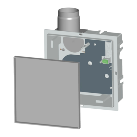
ER GH recessed-
mounted housing
for
ER EC systems
Table of
Contents
Previous
Page
Next
Page
1
2
3
4
5
Advertisement
Table of Contents
Need help?
Do you have a question about the ER GH and is the answer not in the manual?
Ask a question
Questions and answers
Related Manuals for Maico ER GH
Fan Maico ER GH AP Installation And Operating Instructions Manual
(125 pages)
Fan Maico ERM 18 Ex e Operating Instructions Manual
Semi-centrifugal duct fans for use in potentially explosive atmospheres (145 pages)
Fan Maico ERM 18 Ex e Operating Instructions Manual
Semi-centrifugal duct fans for potentially explosive atmospheres (121 pages)
Fan Maico ERM 18 E Ex e Instructions Manual
Semi-centrifugal duct fans (23 pages)
Fan Maico ERK 150 Mounting And Operating Instructions
Duct fans (14 pages)
Fan Maico ERK 200 Mounting And Operating Instructions
Duct fans (14 pages)
Fan Maico ER-A Mounting And Operating Instructions
Covers for er ec recess-mounted exhaust air systems (20 pages)
Fan Maico ER-A Installation And Operating Instructions Manual
Er ec covers for er ec flush-/surface-mounted exhaust air systems (according din 18017-3) (16 pages)
Fan Maico ERM 15 Mounting & Operating Instructions
Semi-centrifugal duct fans (8 pages)
Fan Maico ERH 10-04 Installation And Operating Instructions Manual
(32 pages)
Fan Maico ER 60 E Mounting And Operating Instructions
Recess-mounted exhaust air system (45 pages)
Fan Maico ERR 10/1 Series Installation And Operating Instructions Manual
(40 pages)
Fan Maico ERR 10 Series Mounting & Operating Instructions
Centrifugal duct fans (20 pages)
Fan Maico ERR 10/1 Series Installation And Operating Instructions Manual
(48 pages)
Fan Maico ERV 120 Installation And Operating Instructions Manual
(17 pages)
Fan Maico ECA 100 ipro Series Safety Instruction
Small room fans (6 pages)
This manual is also suitable for:
Er ec
0084.0350
0084.0360
Table of Contents
Print
Rename the bookmark
Delete bookmark?
Delete from my manuals?
Login
Sign In
OR
Sign in with Facebook
Sign in with Google
Upload manual
Upload from disk
Upload from URL


Need help?
Do you have a question about the ER GH and is the answer not in the manual?
Questions and answers