Advertisement
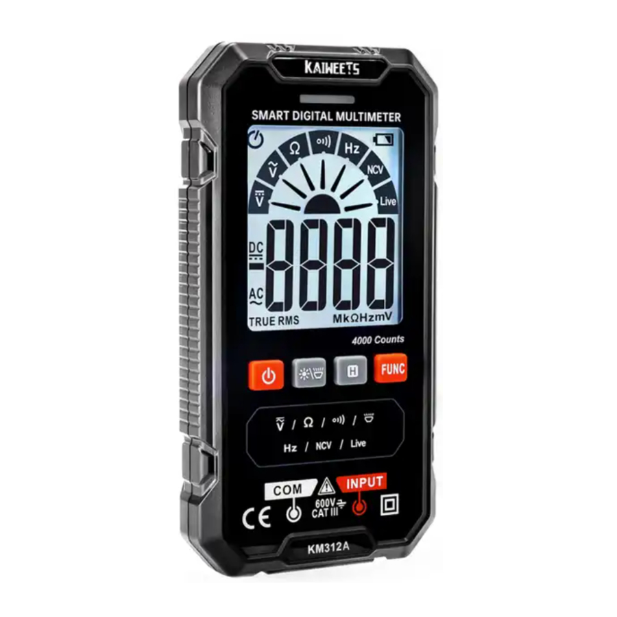
Product Familiarization
Overview

- Indicator Light
- Display
- Buttons
- Jacks
- Flashlight
- NCV Detection Sensor
Features
| Button | Function |
 | Press and hold the '  ' button for about 2 seconds to turn on/off the meter. ' button for about 2 seconds to turn on/off the meter. |
 | Press '  ' button to turn on/off backlight. ' button to turn on/off backlight.Press '  ' button for about 2 seconds to turn on/off flashlight. ' button for about 2 seconds to turn on/off flashlight. |
 | Press 'H' to turn on/ off data holding. Note: Data hold function is invalid in NCV / Live test. |
 | Power on is in SMART mode by default. Press the 'FUNC' button to manual mode. Then press again to switch measurement modes. Press and hold the 'FUNC' key for about 2 seconds to return to the SMART (auto) mode, In SMART Mode, the 'AUTO' signal will be displayed on the screen. |
Display
| Symbol | Description |
 | AC Voltage |
 | DC Voltage |
 | Resistance Test |
 | Audible Continuity Test |
| Hz | Frequency Test |
| NCV | Non-contact Voltage Detection |
| Live | Live Wire Detection |
 | Low Battery |
 | Double insulated |
 | Auto power off It will be on by default and ' ' symbol will be displayed. Without any operation in about 15 minutest the meter will automatically tum off.Press and hold both 'FUNC' and '  ' button to tum on meter, the auto power off function will be canceled. ' button to tum on meter, the auto power off function will be canceled.The ' ' symbol is not displayed. |
SMART (AUTO) Measurement Mode
The Meter defaults to SMART mode. In the SMART mode, the Meter can test DC voltage, AC voltage, resistance, continuity, it selects the range with the best resolution automatically.
Turn on & Ready to use
- Long press the '
![]() ' button for about 2 seconds to turn on the meter, '
' button for about 2 seconds to turn on the meter, ' ![]() ' will be displayed on the screen, and the pointer will swing by itself, indicating the SMART mode.
' will be displayed on the screen, and the pointer will swing by itself, indicating the SMART mode.

- Insert the red probe into 'INPUT' jack and the black probe into the 'COM' jack.

- Touch the red test lead and the black test lead to check whether they are normal. The buzzer will beep and the indicator light will be on if normal.
 ' button for about 2 seconds to turn on the meter, '
  ' will be displayed on the screen, and the pointer will swing by itself, indicating the SMART mode.

Smart mode

Connect the test leads with both ends of the circuit or resistance(in parallel), the Meter automatically selects measurement based on the input.
NOTE:
The minimum measurable voltage in SMART mode is 0.8V.
MANUAL Measurement Mode
The Meter defaults to SMART mode. In the SMART mode, press the 'FUNC' button to switch to manual mode and select function from left to right.
AC/DC voltage measurement
- Turn on & Ready to use
- Press the 'FUNC' button to '
![]() ' setting, '
' setting, ' ![]() ' signal will be displayed on the screen, indicating DC voltage measurement
' signal will be displayed on the screen, indicating DC voltage measurement - Press the 'FUNC' button to '
![]() ' setting, '
' setting, ' ![]() ' signal will be displayed on the screen, indicating AC voltage measurement.
' signal will be displayed on the screen, indicating AC voltage measurement.
 ' setting, '
  ' signal will be displayed on the screen, indicating DC voltage measurement
 ' setting, '
  ' signal will be displayed on the screen, indicating AC voltage measurement.
Resistance measurement
- Turn on & Ready to use
- Press ' FUNC ' button to select '
![]() ' gear. '
' gear. ' ![]() ' signal will be displayed on the screen, indicating the resistance measurement.
' signal will be displayed on the screen, indicating the resistance measurement.
 ' gear. '
 NOTE:
- Do not test parallel circuits. The accuracy of the measurement will be affected.
- Do not directly measure the internal resistance of micrometers, galvanometers, batteries, and other instruments.
Continuity test
- Turn on & Ready to use
- Press ' FUNC ' button to '
![]() ' setting, indicating the continuity measurement.
' setting, indicating the continuity measurement. - Connect the test leads to both ends of the circuit under test (in parallel).
- If the resistance of the circuit or resistor under test is less than 50Ω and the circuit is on position, the buzzer will beep and an indicator light will light up, and the screen will display the measured resistance value.
 ' setting, indicating the continuity measurement.
Frequency measurement
- Turn on & Ready to use
- Press the 'FUNC' button to 'Hz' setting, 'Hz' signal will be displayed on the screen, indicating Frequency testing.
Non-contact voltage detection
- Turn on & Ready to use
- Press the 'FUNC' button to 'NCV' setting, '
![]() ' signal will be displayed on the screen
' signal will be displayed on the screen![]()
- Place the NCV probe closer to the point to be tested gradually.
 ' signal will be displayed on the screen
Live wire detection
- Turn on & Ready to use
- Press the 'FUNC' button to 'Live' setting, '
![]() ' signal will be displayed on the screen.
' signal will be displayed on the screen. - Insert the red probe into the 'INPUT' jack and remove the black probe.

- Touch the object under test with the test lead point.
- When the indicator light lights up that
![]() means the measured position for the fire line, please be careful!
means the measured position for the fire line, please be careful!

When the Meter detects a weak signal, the green indicator will light up, the buzzer will beep in a slow tone, and '--L' will be displayed on the screen.

When the meter detects a strong signal, the red Indicator will light up, the buzzer will beep in a fast tone, and '--H' will be displayed on the screen.

Specifications
| Display Counts: 4000 counts |
| Power: 2 x 1.5V AAA batteries, |
| Sampling Speed: 3 times/second. |
| Environmental conditions: CAT. Ill 600V; Pollution level 2; Altitude < 2000m |
| Working temperature and humidity: 0~40°C(<80% RH, <10°C non condensing) |
| Storage temperature and humidity: -10~60°C(<70% RH, remove the battery) |
| Temperature coefficient: 0.1 x accuracy /°C (<18°C or >28°C) |
| MAX. Voltage between terminals and earth ground: 600V |
Accuracy Specifications
Accuracy is specified for 1 year after calibration, at operating temperatures of 18°C to 28°C, with relative humidity at 0% to 80%.
Accuracy ± ([% of Reading] + [Counts])
| DC voltage | ||
| Range | Resolution | Accuracy |
| 4V | 0.001V | ±(0.5% +3) |
| 40V | 0.01V | |
| 400V | 0.1V | |
| 600V | ||
| AC voltage | ||
| Range | Resolution | Accuracy |
| 4V | 0.001V | ±(0.8% +3) Frequency Response: 40Hz-1 kHz; TRMS |
| 40V | 0.01V | |
| 400V | 0.1V | |
| 600V | ||
| Continuity | ||
 | < Approx. 50Ω, Buzzer will sound and the indicator light will be on. | |
| Resistance | ||
| Range | Resolution | Accuracy |
| 4KΩ | 1Ω | ±(1.0% +5) |
| 40KΩ | 0.01KΩ | |
| 400KΩ | 0.1KΩ | |
| 4MΩ | 0.001MΩ | |
| 40MΩ | 0.01 MΩ | ±(1.5% +10) |
| Overload protection; 250V | ||
| Frequency | ||
| Range | Resolution | Accuracy |
| 4Hz | 0.001Hz | ±(1.0% +3) Overload protection: 250V |
| 40Hz | 0.01Hz | |
| 400Hz | 0.1Hz | |
| 4KHZ | 0.001KHz | |
| 40kHz | 0.01 kHz | |
| 200kHz | 0.1kHz | |
Maintenance
Cleaning
Turn off the power to the Meter and remove the test leads.
Wipe the case with a damp cloth and mild detergent. Dirt or moisture in the terminals can affect readings.
Install Batteries
- Remove test leads from the Meter before opening the case or battery door,
![]() Remove the screw and remove the battery door.
Remove the screw and remove the battery door.- Install 2 x 1.5V AAA batteries,
*Please pay attention to the battery polarity. ![]() Then inserted into the battery door. Install and tighten the battery door screw.
Then inserted into the battery door. Install and tighten the battery door screw.
Safety Information
The meter conforms to IEC61010-1 CATTIII 600V over voltage safety standard and pollution level 2.
A warning identifies conditions and procedures that are dangerous to the user.


To prevent possible electrical shock, fire, or personal injury:
- Read all safety information before you use the product
- Do not alter the product and use only as specified, or the protection supplied by the product can be compromised.
![shock hazard]() Comply with local and national safety codes. Use personal protective equipment (approved rubber gloves, face protection, and flame-resistant clothes) to prevent shock and arc blast injury where hazardous live conductors are
Comply with local and national safety codes. Use personal protective equipment (approved rubber gloves, face protection, and flame-resistant clothes) to prevent shock and arc blast injury where hazardous live conductors are ![]() exposed.
exposed.- Limit operation to the specified measurement category, voltage, or amperage ratings.
- Use Product-approved measurement category (CAT), voltage, and amperage-rated accessories (probes, test leads, and adapters) for all measurements.
- Do not touch voltages >30 V ac RMS, 42 V ac peak, or 60 V DC,
- Use the correct terminals, function, and range for measurements.
- Do not use the product around explosive gas, vapor, or in damp or wet environments.
- Do not operate the product with covers removed or the case open.
Hazardous voltage exposure is possible. - Examine the case before you use the product. Look for cracks or missing plastic. Carefully look at the insulation around the terminals.
- Disconnect power and discharge all high-voltage capacitors before you measure resistance, continuity, capacitance, or a diode junction.
- Do not apply more than the rated voltage, between the terminals or between each terminal and earth ground,
 Comply with local and national safety codes. Use personal protective equipment (approved rubber gloves, face protection, and flame-resistant clothes) to prevent shock and arc blast injury where hazardous live conductors are
 Contact us: support@kaiweets.com

@kaiweetstools
Documents / ResourcesDownload manual
Here you can download full pdf version of manual, it may contain additional safety instructions, warranty information, FCC rules, etc.
Advertisement


Need help?
Do you have a question about the KM312AB and is the answer not in the manual?
Questions and answers