Advertisement
Product Familiarization
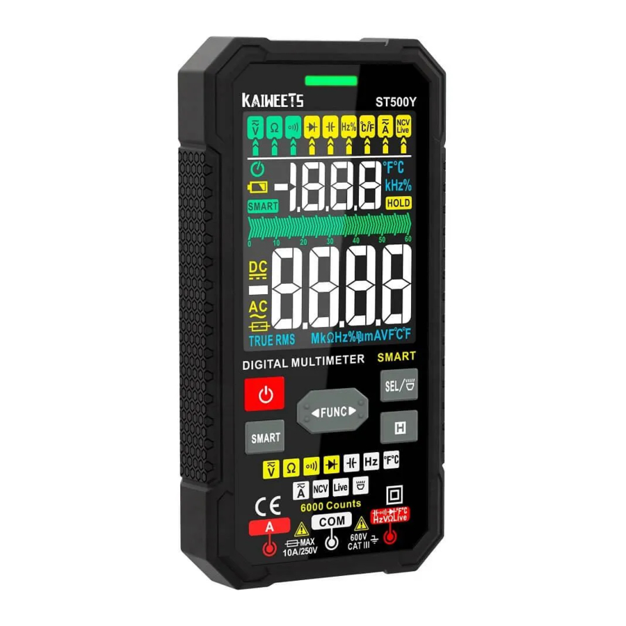
Overview

- Alarm Indicator
- LCD Screen
- Function Buttons
- Current Input Jack
- COM Jack
- Jack for other functions
- NCV Sensor
- Flashlight
Features


Making Measurements
When connecting the test leads to the circuit or device, connect the common (COM) test lead before connecting the live lead: when removing the test leads, remove the live lead before removing the common test lead![]()
- Do not measure the voltage higher than 600V, otherwise, the Meter may be damaged.
![shock hazard]() Pay attention when measuring high voltage to avoid electric shock or personal injury.
Pay attention when measuring high voltage to avoid electric shock or personal injury.- Before use, test the known voltage or current to confirm that the Meter is in good condition.
Turn on & Ready to use
- Long press for about 2 seconds the '
![]() ' button to turn on the Meter, '
' button to turn on the Meter, ' ![]() ' will be displayed on the screen, and the pointer will swing by itself, indicating the SMART mode.
' will be displayed on the screen, and the pointer will swing by itself, indicating the SMART mode.
![]()
- Insert the red probe into '
![]() ' jack and the black probe into the ' COM ' jack.
' jack and the black probe into the ' COM ' jack. - Touch the red test lead and the black test lead to check whether they are normal. The buzzer will beep and the indicator light will be on if normal.
 ' button to turn on the Meter, '
  ' will be displayed on the screen, and the pointer will swing by itself, indicating the SMART mode.
 ' jack and the black probe into the ' COM ' jack.
SMART (AUTO) Measurement Mode
The Meter defaults to SMART mode. In the SMART mode, the Meter can test DC voltage, AC voltage, resistance, continuity, it selects the range with the best resolution automatically.
Smart Mode
Connect the test leads with both ends of the circuit or resistance(in parallel), the Meter![]() automatically selects measurement based on the input,
automatically selects measurement based on the input,
 mode")
NOTE:
The minimum measurable voltage in SMART mode is 0.8V.
When measuring resistance, if the resistance value is less than 50Q, the Meter will beep and the indicator will light up.
MANUAL Measurement Mode
The Meter defaults to SMART mode. In the SMART mode, press the '  ' button to switch to manual mode and select fünction.
AC/DC Voltage Measurement
- Tum on & Ready to use.
- Press the '
![]() ' button to '
' button to ' ![]() ' setting
' setting - '
![]() ' signal will be displayed on the screen, indicating DC voltage measurement.
' signal will be displayed on the screen, indicating DC voltage measurement. - Press the '
![]() ' button to AC voltage test, '
' button to AC voltage test, ' ![]() ' signal will be displayed on the screen, indicating AC voltage measurement.
' signal will be displayed on the screen, indicating AC voltage measurement.
 ' button to '
  ' setting
 ' signal will be displayed on the screen, indicating DC voltage measurement.
 ' button to AC voltage test, '
  ' signal will be displayed on the screen, indicating AC voltage measurement.
Resistance Measurement
- Turn on & Ready to use.
- Press '
![]() ' button to select '
' button to select ' ![]() ' gear.'
' gear.' ![]() ' signal will be displayed on the screen, indicating the resistance measurement.
' signal will be displayed on the screen, indicating the resistance measurement.
 ' gear.'
 NOTE:
Do not directly measure the internal resistance of micrometers, galvanometers, batteries, and other instruments.
Continuity Test
- Tum on & Ready to use.
- Press '
![]() ' button to '
' button to ' ![]() ' setting, indicating the continuity measurement.
' setting, indicating the continuity measurement. - Connect the test leads to both ends of the circuit under test (in parallel),
- If the resistance of the circuit or resistor under test is less than 50Q2 and the circuit is on position, the buzzer will beep and an indicator light will light up, and the screen will display the measured resistance value.
 ' setting, indicating the continuity measurement.
Frequency/Duty Measurement
- Turn on & Ready to use.
- Press the '
![]() ' button to 'Hz%' sefting, 'Hz' signal and ' %' signal will be displayed on the screen, indicating Frequency/Duty Ratio testing.
' button to 'Hz%' sefting, 'Hz' signal and ' %' signal will be displayed on the screen, indicating Frequency/Duty Ratio testing.
![]()

Diode Test
- Tum on & Ready to use
- Press '
![]() ' button to '
' button to ' ![]() ' setting, indicating the diode testing.
' setting, indicating the diode testing. - Connect red test lead with the positive polarity of the diode, black test lead with the negative polarity of the diode.

- If the test leads are connected reversely with the diode polarity, ' OL ' will be displayed.
 ' setting, indicating the diode testing.
Capacitance Measurement
- Turn on & Ready to use
- Press '
![]() ' button to '
' button to ' ![]() ' setting, 'nF' signal will be displayed on the screen, indicating capacitance testing.
' setting, 'nF' signal will be displayed on the screen, indicating capacitance testing.
 ' setting, 'nF' signal will be displayed on the screen, indicating capacitance testing.
* Before measuring the capacitor, discharge the capacitor to avoid damage to the Meter.
* If the capacitance is large, it may take a long time for the reading to stabilize.
Temperature Measurement
- Turn on & Ready to use
- Insert the positive pole of the K-type thermocouple into the '
![]() ' jack and the negative pole into the ' COM ' jack.
' jack and the negative pole into the ' COM ' jack. - Press the '
![]() ' button to '°C/°F' setting, '°C' signal and '°F' signal will be displayed on the screen, indicating temperature testing.
' button to '°C/°F' setting, '°C' signal and '°F' signal will be displayed on the screen, indicating temperature testing. - Touch to the object being measured.
- The reading may take few seconds to be stable.
 ' jack and the negative pole into the ' COM ' jack.
Non-contact AC Voltage Detection
- Turn on & Ready to use
- Press the'«FUNC" button to " NCY * setting, ' NCV ' signal will be displayed on the screen.
- Place the NCV probe closer to the point to be tested gradually.
When the Meter detects a weak signal, the green indicator will light up, the buzzer will beep in a slow tone, and ' --L ' will be displayed on the screen.

When the Meter detects a strong signal, the red indicator will light up, the buzzer will beep in a fast tone, and ' --H " will be displayed on the screen.

Live Wire Detection
- Turn on & Ready to use
- Press the '
![]() ' button to '
' button to ' ![]() '
' - Press the 'SEL' button to 'LIVE' mode.
- Insert the red probe into the '
![]() ' jack and remove the black probe.
' jack and remove the black probe. - Touch the object with the test lead point.
- When the indicator light lights up that means the measured position for the fire line, please be careful!
 '
' ' jack and remove the black probe.
AC/DC Current Measurement
- Tum on & Ready to use
- Insert the red probe into the 'A' jack and the black probe into the 'COM' jack. The Meter will automatically adjust to the '
![]() ' gear.
' gear. - '
![]() ' and 'mA' signal will be displayed on the screen, indicating DC current measurement.
' and 'mA' signal will be displayed on the screen, indicating DC current measurement. - Press the ' SEL ' button, 'mA' signal and '
![]() ' signal will be displayed on the screen, indicating AC current measurement.
' signal will be displayed on the screen, indicating AC current measurement.
 ' gear.
 ' and 'mA' signal will be displayed on the screen, indicating DC current measurement.
 ' signal will be displayed on the screen, indicating AC current measurement.
Note:
- When measuring AC current, the frequency will be displayed, and when measuring DC current, the ambient temperature will be displayed on the screen.
- 'LEAD' signal will be displayed on the screen when the test leads are connected incorrectly, please insert the red test lead into 'A' Jack.
![]()
- The Meter will turn to the current testing when you insert the lead into 'A' Jack and 'COM' Jack. For safety, users cannot switch the functions.
- Do not measure current > 10 A in this gear, in case of the fuse burning.

Specifications

Accuracy Specifications
Accuracy is specified for 1 year after calibration, at operating temperatures of 18°C to 28°C, with relative humidity at 0% to 80%.
Accuracy ± ([% of Reading] + [Counts])

DC voltage

AC voltage

Temperature

Resistance

AC/DC current

Diode/Continuity

Capacitance

Frequency/Duty
Maintenance
Cleaning
- Turn off the power to the Meter and remove the test leads.
- Wipe the case with a damp cloth and mild detergent. Dirt or moisture in the terminals can affect readings.
![]()
Always keep the inside of the Meter clean and dry to prevent electric shock or damage.

Install Batteries
'  ' signal will be displayed on the screen when the battery is low.
- Remove test leads from the Meter before opening the case or battery door.
- Remove the screw and remove the battery door.
- Install 4 x 1.5V AAA batteries. *Please pay attention to the battery polarity.
- Then inserted into the battery door. Install and tighten the battery door screw.
![]()
To avoid electric shock or personal injury caused by wrong reading, please replace the battery immediately when the battery is low.- Do not discharge the battery by shorting it or reversing its polarity.
- To operate and maintain the Meter safely, please take out the battery when it is not used for a long time to prevent the battery leakage from damaging the product.
Replace Fuses
'  ' signal will be displayed on the screen when the fuses are blown, current testing function is not working, please change the fuses.
- Tum off the Meter power and remove the probes.
- Remove the screw fixing the back cover and remove the back cover.
- Remove the burnt-out fuse, replace it with a new one of the specification(F10A/250V fuse), and ensure that the fuse is installed in the safety clip and clamped tightly.
- Install the back cover and fix it with screws

- Use ONLY a fuse with the amperage, interrupt voltage, and speed ratings specified.
- Do not use the Meter if the back cover is opened.
Safety Information
The Meter conforms to IEC61010-1 CAT.III 600V overvoltage safety standard and pollution level 2.
A Warning identifies conditions and procedures that are dangerous to the user.
Warnings


To prevent possible electrical shock, fire, or personal injury:
- Read all safety information before you use the Product,
- Do not alter the Product and use only as specified. or the protection supplied by the Product can be compromised.
![shock hazard]() Comply with local and national safety codes. use personal protective equipment (approved rubber gloves, face protection, and flame-resistant clothes) to prevent shock and arc blast injury where hazardous live conductors are exposed.
Comply with local and national safety codes. use personal protective equipment (approved rubber gloves, face protection, and flame-resistant clothes) to prevent shock and arc blast injury where hazardous live conductors are exposed.- Limit operation to the specified measurement category, voltage, or amperage ratings.
- Use Product-approved measurement category (CAT), voltage, and amperage-rated accessories (probes, test leads, and adapters) for all measurements,
- Do not touch voltages >30V AC RMS, 42V AC peak, or 60V DC,
- Use the correct terminals, function, and range for measurements.
- Do not use the Product around explosive gas, vapor, or in damp or wet environments.
- Do not operate the Product with covers removed or the case open. Hazardous voltage exposure is possible.
- Examine the case before you use the Product. Look for cracks or missing plastic. Carefully look at the insulation around the terminals.
- Disconnect power and discharge all high-voltage capacitors before you measure resistance, continuity, capacitance, or a diode junction
![]()
- Do not apply more than the rated voltage, between the terminals or between each terminal and earth ground.
- Remove circuit power before you connect the Product in the circuit when you measure current, Connect the Product in series with the circuit.
- Measure a known voltage first to make sure that the Product operates correctly.
- Do not use test leads if they are damaged. Examine the test leads for damaged insulation, exposed metal, or if the wear indicator shows. Check test lead continuity.
- Remove the input signals before you clean the Product
- When measuring, please connect the null or ground wire first, then the live wire; when disconnected, please disconnect the live wire first, and then the null or ground wire,
- Remove the probe from the Meter before opening the case or battery cover. Do not use the Meter when the Meter is disassembled or the battery cover is opened.
- The Meter can only be used together with the probe provided to meet the requirements of the safety standard. If the probe is damaged and needs to be replaced, the probe of the same model and electrical specification.
Contact us: support@kaiweets.com

Documents / ResourcesDownload manual
Here you can download full pdf version of manual, it may contain additional safety instructions, warranty information, FCC rules, etc.
Advertisement


Need help?
Do you have a question about the ST500Y and is the answer not in the manual?
Questions and answers