Table of Contents
Advertisement
Advertisement
Table of Contents

Subscribe to Our Youtube Channel
Related Manuals for Kaiweets HT118A


Summary of Contents for Kaiweets HT118A
- Page 1 True-RMS Multimeter Model: HT118A...
-
Page 2: Table Of Contents
Table of Contents Statement................1 Safety Instructions............2 Symbols................ 5 Multimeter Features............6 FUNC. keys..............7 Data hold..............7 MIN MAX Measurement..........7 Backlight............... 7 Flashlight..............7 Sleep Mode..............8 LED-Terminal Indication..........8 High voltage prompt function........8 Measurement Operation............ 9 DC/AC voltage measurement........9 DC/AC voltage mV measurement......10 Frequency/Duty measurement....... - Page 3 Temperature Measurement........19 General Specifications............. 20 Accuracy Specifications........... 21 DC voltage..............21 AC voltage..............22 DC current..............22 AC current..............23 Resistance..............23 Capacitance............... 24 Frequency/Duty............24 Diode test..............26 Continuity test............26 Temperature...............26 Maintenance..............27 Clean................27 Replace Battery and Fuse........27...
-
Page 4: Statement
Statement In accordance with the international copyright law, without permission and written consent, do not copy the contents of this manual in any form (including storage and retrieval or translation into languages of other countries or regions). The manual is subject to change in future edition without prior notice. -
Page 5: Safety Instructions
Safety Instructions The instrument is designed according to the requirements of the international electrical safety standard IEC61010-1 for the safety requirements of the electronic testing instruments. The design and manufacture of instruments strictly comply with the requirements of IEC61010-1 CAT.III 1000V over voltage safety standards and pollution level 2. - Page 6 Before using the instrument, please check whether there is any crack or plastic damage in the instrument case. If you do, do not use it again. Before using the instrument, please check whether the probe is cracked or damaged. If so, please replace the same type and the same electrical specifications.
- Page 7 remove the probe on the instrument. Do not use the instrument in the circumstances that the instrument is taken apart or battery cover is opened. It only meets the safety standards when the instrument is used together with the supplied probe. If the probe is damaged and needs to replace, the probe with same model number and same electrical specifications must be used for replacement.
-
Page 8: Symbols
Symbols High voltage warning AC (Alternating Current) AC and DC DC (Direct current) Warning; Important information Earth ground Fuse Low Battery Double insulated Product complies with all relevant European laws Do not dispose of this product as unsorted municipal waste. Product is suitable for testing and measuring circuits directly connected CAT. -
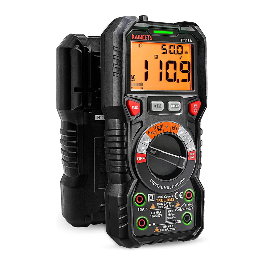
Page 9: Multimeter Features
Multimeter Features A new generation of high performance digital multimeter. The new display and function layout show clearer and better user experience. It is the best choice for professional electricians, enthusiasts or families. NCV probe Flashlight Red / green light LCD display (Dual color backlight) Function keys... -
Page 10: Func. Keys
FUNC. keys When there are multiple measuring functions on a gear, the FUNC. key switch function is adopted. Data hold Press”HOLD” key, enter/cancel data hold mode. MIN MAX Measurement Press the MAX/MIN key to enter the MIN MAX mode and then press the loop to display the maximum and minimum values. -
Page 11: Sleep Mode
Sleep Mode The Meter automatically enters sleep mode if there is no operation for 15 minutes to save battery energy. Pressing any button or turning the rotary switch awakes the Meter. If you press the "FUNC." button and turn on the meter, the sleep mode will be deactivated. -
Page 12: Measurement Operation
Measurement Operation DC/AC voltage measurement 1) Turn the knob to “ ” and switch DC/AC voltage function by "FUNC." key 2) Insert the probe in “ ” terminal, insert the black probe in “COM” terminal. 3) Connect the probe to the measured circuit (connect to the measured power supply or circuit in parallel), measure the voltage. -
Page 13: Dc/Ac Voltage Mv Measurement
DC/AC voltage mV measurement 1) Turn the knob to “ ” and switch AC/ DC voltage function by "FUNC." key 2) Insert the probe in “ ” terminal, insert the black probe in “COM” terminal. 3) Contact the probe to the measured circuit (connect to the measured power supply or circuit in parallel), measure the voltage. -
Page 14: Frequency/Duty Measurement
Frequency/Duty measurement 1) Turn the knob to “Hz%” and switch Frequency or Duty function by "FUNC." key 2) Insert the probe in “ ” terminal, insert the black probe in “COM” terminal. 3) Contact the probe to the measured circuit (connect to the measured power supply or circuit in parallel), measure the frequency and duty. -
Page 15: Dc/Ac Current Measurement
DC/AC current measurement 1) Turn the knob to “ ” or “ ” or “ ” and switch AC or DC current function by "FUNC." key 2) Insert the probe in “mA” terminal or “10A” terminal, insert the black probe in “COM” terminal. 3) Disconnect the power of the tested circuit;... -
Page 16: Resistance Measurement
Resistance measurement 1) Turn the knob to “ ” and switch resistance function by "FUNC." key 2) Insert the probe in “ ” terminal, insert the black probe in “COM” terminal. 3) Contact the probe to the measured circuit or resistance, measure the resistance. -
Page 17: Continuity Measurement
Continuity measurement 1) Turn the knob to “ ” and Switch to Continuity function by "FUNC." key. 2) Insert the probe in “ ” terminal, insert the black probe in “COM” terminal. 3) Contact the probe to the measured circuit or resistance, 4) If the resistance or circuit of the measured resistance is less than 30Ω, the buzzer will on and the green indicator lights up at the same time;... -
Page 18: Diode Measurement
Diode measurement 1) Turn the knob to “ ” and Switch to diode measurement function by "FUNC." key. 2) Insert the probe in “ ” terminal, insert the black probe in “COM” terminal. 3) Touch the diode anode with the red probe, the black probe contacts the diode cathode. -
Page 19: Capacitance Measurement
Capacitance measurement 1) Turn the knob to “ ”. 2) Insert the probe in “ ” terminal, insert the black probe in “COM” terminal. 3) Contact the probe to the measured circuit or Capacitance, measure the resistance. 4) Read the measurement result on the screen. 5) WARNING When measuring Capacitance on the line, disconnect the power supply and discharge all the high-voltage capacitors. -
Page 20: Ncv Test
NCV test 1) Turn the knob to the “ ” and Switch to NCV test function by "FUNC." key. Meter will display "NCV". 2) Then NCV probe gradually approaches the detected point. 3) When the meter senses weak AC signals, the green indicator lights up, at the same time, the beeps send out slow dips. -
Page 21: Live Test
Live test 1) Turn the knob to the “ ”, and Switch to live test function by "FUNC." key. Meter will display "LIVE". 2) Insert the probe in “ ” terminal, Then the probe contact to the test point 3) When the meter senses weak AC signals, the green indicator lights up, at same time, the beeps send out slow dips. -
Page 22: Temperature Measurement
Temperature Measurement 1) Turn the knob to the “ ”. 2) Insert the K-Type thermocouple into the meter. The thermocouple's positive (red) is inserted into the " " input, and the negative end (black) is inserted into the "COM" input. 3) Connect the measured object with the thermocouple probe and read the result from the display. -
Page 23: General Specifications
General Specifications Display 6000 counts, true RMS Measurements Safety Rating CAT. IV 600V ; CAT. III 1000V MAX. Voltage between terminals DC1000V/AC750V and earth ground mA : F600mA/250V fuse Fuse protection 10A : F10A/250V fuse Sampling rate: 3 times/second Terminal indication Auto Battery 2 x 1.5V AAA batteries... -
Page 24: Accuracy Specifications
Accuracy Specifications The accuracy applies within one year after the calibration. Reference condition: the environment temperature 18°C to 28°C, the relative humidity is no more than 80. Accuracy: ( reading + word) DC voltage Range Resolution Accuracy 600mV 0.1mV 0.001V ±(0.5% reading+3) 0.01V 600V... -
Page 25: Ac Voltage
AC voltage Range Resolution Accuracy 600mV 0.1mV 0.001V ±(0.8% reading+5) 0.01V 600V 0.1V 750V Input impedance:10MΩ; Maximum input voltage: 750V AC Overload protection: 1000V DC or 750V AC; Frequency Response : 10Hz ~ 1kHz ; True-RMS DC current Range Resolution... -
Page 26: Ac Current
AC current Range Resolution Accuracy 600A 0.1A 6000A 1A ±(1.5% reading+3) 60mA 0.01mA 600mA 0.1mA 0.01A Overload protection : A/mA : F600mA/250V fuse 10A : F10A/250V fuse Maximum input current : mA: 600mA ; A: 10A Frequency Response : 10Hz ~ 1kHz ; True-RMS ... -
Page 27: Capacitance
Capacitance Range Resolution Accuracy 10nF 0.001nF 100nF 0.01nF 1000nF 0.1nF ±(4.0% reading+5) 10F 0.001F 100F 0.01F 1000F 0.1F 10mF 0.001mF ±(5.0% reading+5) 100mF 0.01mF Overload protection : 250V Note: the parameters do not include errors caused by the capacitance of the pen capacitor and the substrate. - Page 28 Hz/duty : 1) Range : 0 ~ 10MHz 2) Voltage sensitivity : 0.2~10V AC 3) Overload protection : 250V; V : 1) Range : 0 ~ 100 kHz 2) Voltage sensitivity : 0.5~600V AC3); A 、 mA 、 A : 1) Range :...
-
Page 29: Diode Test
Diode test Forward DC current is about 2.5mA Function Reverse DC voltage is about 3V It displays the approximate Overload protection:250V forward voltage value of the diode. Continuity test Function Reverse voltage about 3V The resistance is <30, the buzzer will Overload protection:250V sound and the indicator light is green. -
Page 30: Maintenance
Maintenance Clean If there’s dust on the terminal or the terminal is wet, it may cause measurement error. Please clean the instrument according to the steps below: 1) Switch off the power supply of the instrument, and remove the test probe. 2) Turn over the instrument and shake out the dust accumulated in the input terminal. - Page 31 the battery cover with screws. 4) WARNING o prevent electric shock or personal injury caused by error reading, please replace the battery promptly when the battery power is low. Please do not make battery short circuit or reverse battery polarity to discharge the batteries. ...
- Page 32 5) WARNING To avoid possible electric shock, personal injury or instrument damage, please use the fuse with same specifications or specified specifications. EN18118AV10...
Need help?
Do you have a question about the HT118A and is the answer not in the manual?
Questions and answers