Advertisement
- 1 Product Description
- 2 Operating Introduction
-
3
Measurement Operation
- 3.1 Smart Measurement Mode
-
3.2
Professional measurement
- 3.2.1 ACIDC voltage measurement
- 3.2.2 AC/DC current measurement
- 3.2.3 Resistance measurement
- 3.2.4 Continuity test
- 3.2.5 AC/DC mV voltage measurement
- 3.2.6 Frequency/Duty measurement
- 3.2.7 Capacitance measurement
- 3.2.8 Diode test
- 3.2.9 Temperature measurement
- 3.2.10 Non-contact AC voltage detection
- 3.2.11 Live wire detecting
- 4 General Technical Specifications
- 5 Accuracy Specifications
- 6 Maintenance
- 7 Safety Specification
- 8 Documents / Resources
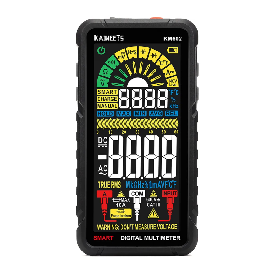
Product Description
Overview

- Charging Port
- Power Button
- Select Button
- FUNC Button
- LCD Display Screen
- Current Jack
- COM Jack
- Input Jack
- Flashlight/Hold Button
- MAX/MIN Button
- Flashlight
- FUSE Location
Function buttons
 | Press and hold the button for about 2 seconds to turn the power on or off. |
 | Press the FUNC button to select the appropriate measurement function. Long press the FUNC button to enter the smart measurement mode. |
 | Press the SEL button to select specific functions of the composite function. For example, you can press "  " button to select " " button to select " " gear, and then press the " " gear, and then press the " " button to select AC voltage or DC voltage. " button to select AC voltage or DC voltage. |
 | Press the button briefly to activate/cancel data hold on function. Long press the button for about 2 seconds to turn on/off the Flashlight. |
 | Short press the button to enter the maximum and minimum measurement function, while displaying the maximum value. Another short press to cycle through the maximum and minimum values. Another long press for about 2 seconds to return to normal measurement. |
Display

Operating Introduction
Gear selection
Press the " " button to activate the manual gear selection mode to choose a suitable measurement function.
Press the " " button to choose AC or DC mode when measuring AC/DC voltage and AC/DC current.
Press and hold the " " button for 2 seconds in any position to return to AUTO mode,
Power on default in SMART (AUTO) measurement mode.
Fuse broken indication
The LCD display shows " " symbol when the fuse is blown and a lead is inserted in the A-jack and no further measurements will be taken.

Replace fuse
- Turn off the meter power and remove the probes.
- Remove the screw fixing the back cover and remove the back cover.
- Remove the burnt out fuse, replace it.
- With a new one of the same specification, and ensure that the fuse is installed in the safety clip and clamped tightly.
- Install the back cover and fix it with screws.
 Note: After opening the back cover, don't use the meter for measurement to prevent electric shock or damage.
Probe terminal prompt
When changing gears, the corresponding input jack light will flash 5 times, so convenient for you to insert the test leads into the correct jack.
Automatic recognition of current measurement
When the current A jack is inserted, the meter jumps to " " gear and enters current measurement automatically, and gear switching is not allowed.
When manually switched to current gear with no lead in A-jack, LCD displays "LEAd" and no further measurement taken.
Automatic turn off
Press the " " button to power on, with automatic turn-off function by default and "" symbol displayed on LCD. After 15 minutes of inactivity, the device will turn off automatically to save battery energy.
When the device is turned off, pressing and holding the " " and "" buttons at the same time, then power on the device to cancel the automatic turn-off function. The "" symbol is not displayed, and an audible prompt when the automatic turn-off function is canceled.
Charging mode
When enter the charging mode, do not take measurements.
- CHARGE symbol is displayed on screen, analog bar scrolling with batter level percentage displayed.
- "WARNING: DON'T MEASURE VOLTAGE" displays at the bottom of the screen.


Note:
- About 3 hours to be fully charged
- Charger specification: 5V 1A
Measurement Operation

- Do not measure the voltage higher than 600V, otherwise the meter may be damaged.
- Pay special attention to safety when measuring high voltage to avoid electric shock or personal injury.
- Before use, test the known voltage with the meter to confirm that the meter is in good condition.
Smart Measurement Mode
The Meter defaults to SMART mode. In the SMART mode, AC/DC voltage, resistance, continuity can be measured, and the meter can automatically identify the measurement signal.
- Long press "
![]() " button for about 2 seconds to power on, display
" button for about 2 seconds to power on, display ![]() and enter the intelligent measurement mode.
and enter the intelligent measurement mode. - Insert the red probe into "INPUT" jack and the black probe into the "COM" jack.
- Connect the test leads With both ends of the circuit or resistance, the Meter automatically selects measurement based on the input.
- When measuring the resistance, the resistance value is less than about 500, the buzzer sounds.
- Read the results from the display.
 and enter the intelligent measurement mode.
Professional measurement
ACIDC voltage measurement
- Long press "
![]() " button for about 2 seconds to power on, display
" button for about 2 seconds to power on, display ![]() and enter the intelligent measurement mode.
and enter the intelligent measurement mode. - Press "
![]() " button to select "
" button to select "![]() " gear, press the "
" gear, press the "![]() " button to select DC voltage, "
" button to select DC voltage, "![]() " signal will be displayed on the screen, indicating DC voltage measurement.
" signal will be displayed on the screen, indicating DC voltage measurement. - Press "
![]() " button to select "
" button to select "![]() " gear, press the "
" gear, press the "![]() " button to select AC voltage, "
" button to select AC voltage, "![]() " signal will be displayed on the screen, indicating AC voltage measurement,
" signal will be displayed on the screen, indicating AC voltage measurement, - Insert the red probe into "INPUT" jack and the black probe into the "COM" jack.
- Contact the probe with both ends of the measured power supply.
- Read the results from the display.
 " button to select "
 " gear, press the "
 " button to select DC voltage, "
 " signal will be displayed on the screen, indicating DC voltage measurement.
 " signal will be displayed on the screen, indicating AC voltage measurement,
Resistance: about 10M
Frequency response: 40Hz~1kHz true RMS
AC/DC current measurement
- Long Press "
![]() " button for about 2 seconds to power on, display
" button for about 2 seconds to power on, display ![]() and enter the intelligent measurement mode.
and enter the intelligent measurement mode. - Press "
![]() " button to select "
" button to select "![]() " gear, Or insert the red probe into the A jack to automatically select the "
" gear, Or insert the red probe into the A jack to automatically select the "![]() " gear.
" gear. - Press "
![]() " button to switch AC or DC current measurement.
" button to switch AC or DC current measurement. - Insert the red probe into A jack and the black probe into the "COM" jack.
- Disconnect the measured power supply, connect the meter with the power supply, and then turn on the measured power supply.
- Read the results from the display.
 " gear, Or insert the red probe into the A jack to automatically select the "
 " gear.
 " button to switch AC or DC current measurement.
Overload protection: F10A/250V fuse
Response frequency: 40Hz~1kHz, True RMS
Resistance measurement
- Long press "
![]() " button for about 2 seconds to power on, display
" button for about 2 seconds to power on, display ![]() and enter the intelligent measurement mode.
and enter the intelligent measurement mode. - Press "
![]() " button to select "
" button to select "![]() " gear. "
" gear. "![]() " signal will be displayed on the screen, indicating the resistance measurement (the resistance value is less than about 50
" signal will be displayed on the screen, indicating the resistance measurement (the resistance value is less than about 50![]() The buzzer sounds).
The buzzer sounds). - Insert the red probe into "INPUT" jack and the black probe into the "COM" jack.
- Contact the probe with both ends of the measured resistance.
- Read the results from the display.
 " button to select "
 " gear. "
Overload protection: 250V
Continuity test
- Long press "
![]() " button for about 2 seconds to power on, display
" button for about 2 seconds to power on, display ![]() and enter the intelligent measurement mode.
and enter the intelligent measurement mode. - Press "
![]() " button to select "
" button to select "![]() " gear.
" gear. - Insert the red probe into "INPUT" jack and the black probe into the "COM" jack.
- Contact the probe with both ends of the measured resistance or circuit.
- When the resistance value is less than about 50
![]() the buzzer sounds.
the buzzer sounds.
 " gear.
AC/DC mV voltage measurement
- Long press "
![]() " button for about 2 seconds to power on, display
" button for about 2 seconds to power on, display ![]() and enter the intelligent measurement mode.
and enter the intelligent measurement mode. - Press "
![]() " button to select "
" button to select "![]() " gear; press the "
" gear; press the "![]() " button to select DC voltage, "
" button to select DC voltage, "![]() " signal will be displayed on the screen, indicating DC mV voltage measurement.
" signal will be displayed on the screen, indicating DC mV voltage measurement. - Press "
![]() " button to select "
" button to select "![]() " gear, press the "
" gear, press the "![]() " button to selectAC voltage, "
" button to selectAC voltage, "![]() " signal will be displayed on the screen, indicating AC voltage measurement.
" signal will be displayed on the screen, indicating AC voltage measurement. - Insert the red probe into "INPUT" jack and the black probe into the "COM" jack.
- Contact the probe with both ends of the measured power supply.
- Read the results from the display.
 " gear; press the "
 " signal will be displayed on the screen, indicating DC mV voltage measurement.
 " signal will be displayed on the screen, indicating AC voltage measurement.
Frequency/Duty measurement
- Long press "
![]() " button for about 2 seconds to power on, display
" button for about 2 seconds to power on, display ![]() and enter the intelligent measurement mode.
and enter the intelligent measurement mode. - Press "
![]() " button to select "
" button to select "![]() " gear, "Hz" signal and "%" will be displayed on the screen, indicating Frequency/Duty testing.
" gear, "Hz" signal and "%" will be displayed on the screen, indicating Frequency/Duty testing. - Insert the red probe into "lNPUT" jack and the black probe into the "COM" jack.
- Contact the probe with both ends of the measured power supply.
- Read the results from the display.
 " gear, "Hz" signal and "%" will be displayed on the screen, indicating Frequency/Duty testing.
Overload protection: 250M
Capacitance measurement
- Long press "
![]() " button for about 2 seconds to power on, display
" button for about 2 seconds to power on, display ![]() and enter the intelligent measurement mode.
and enter the intelligent measurement mode. - Press "
![]() " button to select "
" button to select "![]() " gear, "nF" signal will be displayed on the screen, indicating capacitance testing.
" gear, "nF" signal will be displayed on the screen, indicating capacitance testing. - Insert the red probe into "INPUT" jack and the black probe into the "COM" jack.
- Contact the probe With 50th ends of the measured capacitance.
- Read the results from the display.
 " gear, "nF" signal will be displayed on the screen, indicating capacitance testing.
Overload protection: 250V
Diode test
- Long press "
![]() " button for about 2 seconds to power on, display
" button for about 2 seconds to power on, display ![]() and enter the intelligent measurement mode.
and enter the intelligent measurement mode. - Press "
![]() " button to select "
" button to select "![]() " gear, indicating the diode testing.
" gear, indicating the diode testing. - Insert the red probe into "INPUT" jack and the black probe into the "COM" jack.
- The red probe contacts the anode of the diode and the black probe contacts the cathode of the diode.
- If the probe polarity is opposite to the diode polarity, the display will display "OL".
- Read the results from the display.
 " gear, indicating the diode testing.
Open circuit voltage: about 3V
Temperature measurement
- Long press "
![]() " button for about 2 seconds to power on, display
" button for about 2 seconds to power on, display ![]() and enter the intelligent measurement mode.
and enter the intelligent measurement mode. - Press "
![]() " button to select "oC/oF" gear, "oC" signal and "oF" signal will be displayed on the screen (Default is oF), indicating temperature testing.
" button to select "oC/oF" gear, "oC" signal and "oF" signal will be displayed on the screen (Default is oF), indicating temperature testing. - Insert the positive pole of the K-type thermocouple into the "INPUT" jack and the negative pole into the "COM" jack.
- The thermocouple probe contacts the measured object.
- Read the results from the display.
Non-contact AC voltage detection
- Long press "
![]() " button for about 2 seconds to power on, display
" button for about 2 seconds to power on, display ![]() and enter the intelligent measurement mode.
and enter the intelligent measurement mode. - Press "
![]() " button to select "NCV/Live" gear, "NCV" signal will be displayed on the screen, indicating the NCV testing.
" button to select "NCV/Live" gear, "NCV" signal will be displayed on the screen, indicating the NCV testing. - Place the NCV sensor area closer to the point to be tested gradually.
- When the weak electric field signal is detected, it will display "--L" the buzzer will sound slowly; when the strong electric field signal is detected, it will display "--H", the buzzer will sound quickly.
Live wire detecting
- Long press for "
![]() " button about 2 seconds to power on, display
" button about 2 seconds to power on, display ![]() and enter the intelligent measurement mode.
and enter the intelligent measurement mode. - Press "
![]() " button to select "NCV/Live" gear, press the "
" button to select "NCV/Live" gear, press the "![]() " button to switch to live wire measurement, the "LIVE" symbol will show on the screen, indicating the Live testing.
" button to switch to live wire measurement, the "LIVE" symbol will show on the screen, indicating the Live testing. - Insert the red probe into "INPUT" jack and remove the black probe.
- Use the red probe contact the conductor.
- When the weak electric field signal is detected, it will display "--L" and the buzzer will sound slowly;
- When the strong electric field signal is detected, it will display "--H"; the buzzer will sound quickly.
General Technical Specifications

Accuracy Specifications
The accuracy applies within one year after the calibration.
Reference condition: the environment temperature 18°C to 28°C, the relative humidity is no more than 80%.
Accuracy: ±(%reading + words)
DC Voltage

AC Voltage

Resistance

AC/DC Current

Capacitance

Frequency/Duty

Diode/Continuity

Temperature

Maintenance
Clean
When cleaning the meter, please follow the following Steps:
- Turn off the meter power and remove the probes.
- Wipe the case with a damp cloth or mild detergent. Do not use abrasives or solvents. Wipe the contacts in each input socket with a clean swab soaked in alcohol.
Note: Always keep the inside of the meter clean and dry to prevent electric shock or damage to the meter.
Safety Specification
To avoid possible electric shock or personal injury, please observe the following specifications:
- Please read this manual carefully and pay special attention to safety warning information before using the meter.
- Operate the meter according to the manual, otherwise the protection function provided by the instrument may be damaged or weakened.
- Take special care when measuring values that above 60M dc, 30V ac RMS, 42V peak. This kind of voltage has the danger of electric shock.
- Do not measure voltage higher than the rated value between terminals or between terminals and ground.
- Measure the known voltage to check whether the meter works normally. If it is not normal or damaged, please do not use it again.
- Before using the meter, please check whether there are cracks or damaged plastic parts in the instrument shell. If so, please do not use it again.
- Before using the meter, please check whether the probe is cracked or damaged. If so, please replace the probe with the same model and electrical specification.
- Please use the meter according to the measurement category, voltage or current rating specified in the meter or manual.
- Please observe local and national safety regulations. Wear personal protective equipment (such as approved rubber gloves, masks and flame retardant clothing, etc.) to prevent injury caused by electric shock and electric arc when dangerous live conductors are exposed.
- When the "
![]() " symbol is displayed on the meter, please charge battery in time to prevent measurement error.
" symbol is displayed on the meter, please charge battery in time to prevent measurement error. - Do not use the meter in the environment with explosive gas or steam or humid environment.
- When using the probe, please hold your fingers behind the probe finger guard.
- When measuring, please connect the null or ground wire first, then the live wire; when disconnected, please disconnect the live wire first, and then the null or ground wire.
- Remove the probe from the meter before opening the case or battery cover. Do not use the meter when the meter is disassembled or the battery cover is opened.
- The meter can only be used together with the probe provided to meet the requirements of the safety standard. If the probe is damaged and needs to be replaced, the probe of the same model and electrical specification must be replaced.
 " symbol is displayed on the meter, please charge battery in time to prevent measurement error.
Safety symbol meaning
| Simbols | Description | Simbols | Description |
| WARNING, RISK OF DANGER. |  | WARNING. RISK OF ELECTRIC SHOCK. |
 | Hazardous Voltage |  | Conforms to European Union directives |
| CAT Il | Suitable for testing circuits directly connected to power points (sockets and similarities) of low voltage power installations. | ||
| CAT III | Suitable for measuring Circuits connected to the distribution part of Iow voltage power supply devices in building | ||
| CAT IV | Suitable for measuring circuits connected to the power supply of low voltage power installations in buildings. | ||

Documents / ResourcesDownload manual
Here you can download full pdf version of manual, it may contain additional safety instructions, warranty information, FCC rules, etc.
Advertisement


Need help?
Do you have a question about the KM602 and is the answer not in the manual?
Questions and answers