Advertisement
Product Description
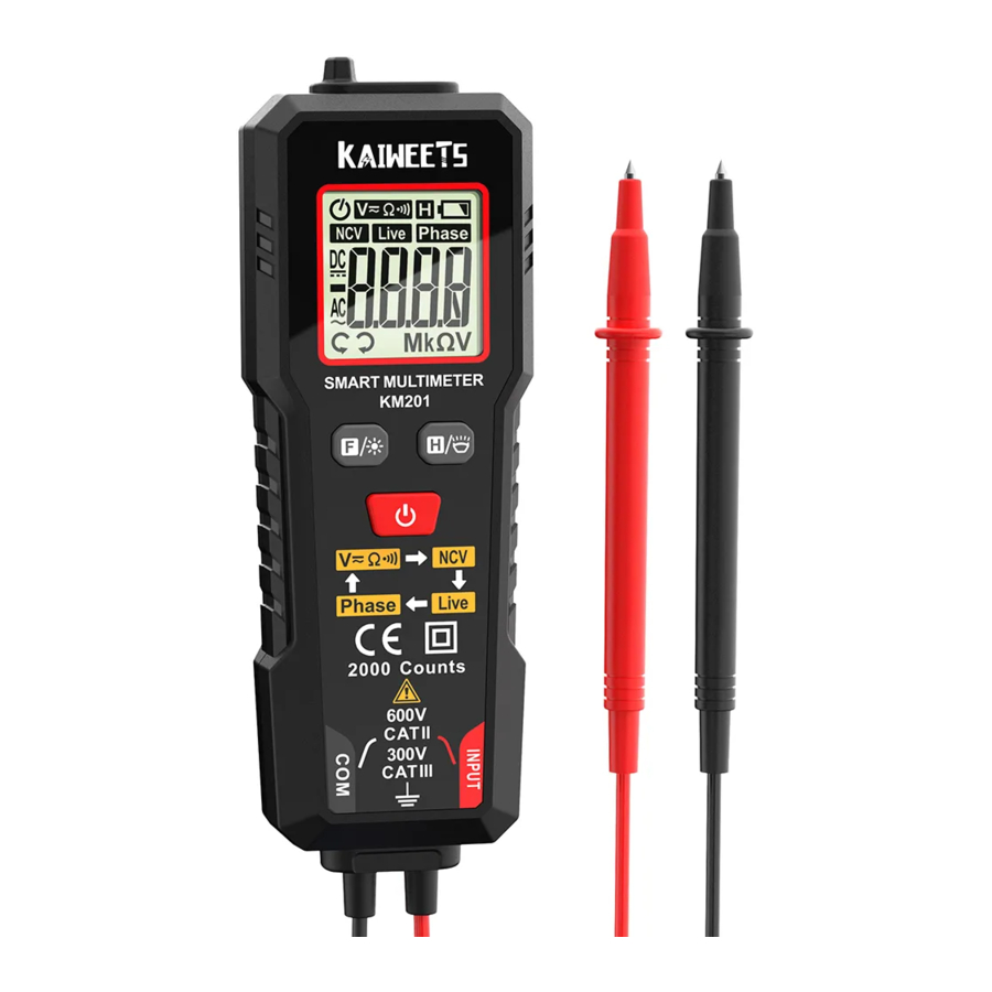
Safety Symbol Meaning

Multimeter Features

- NCV probe
- Flashlight
- Display
- Function buttons.
- Function indication description
- Com (black test lead)
- Input (red test lead)
Function buttons

Sleep Mode
The Meter automatically enters sleep mode if there is no operation in 15 minutes to save battery energy.
Press the "![]() ", then press the "
", then press the " " at the Same time to turn on the meter. Auto — off function Will be canceled.
Measurement operation
Auto Mode
 Don't use i t to test voltage over 600V, the meter may be damaged. Always test known voltage with the meter before using to confirm the instrument function is intact.
- Long press the "
![]() " to power on, and the display shows "AUTO", it defaults AUTO mode. Or Short press "
" to power on, and the display shows "AUTO", it defaults AUTO mode. Or Short press "![]() " to select AUTO mode.
" to select AUTO mode. - Connect the test leads o the source or load to be measured.
- The meter automatically recognizes voltage, resistance, and continuity.
- Read the measurement result from the display.
Note: If the resistance value of the measured resistor or circuit is less than 500Ω, the buzzer will beep and the green backlight will be lit.
NCV measurement
- Short press the "
![]() " button to switch to NCV function. The meter will display "NCV".
" button to switch to NCV function. The meter will display "NCV". - Then NCV probe gradually approaches the detected point.
- When the meter senses weak AC signals, the green backlight lits and meter beeps slowly. The display shows "---L".
- When the meter senses strong AC signals, the red backlight lits and meter beeps fast. The display shows "---H".
LIVE measurement
- Short press the "
![]() " button to switch to LIVE function. The meter will display "Live".
" button to switch to LIVE function. The meter will display "Live". - Connect the red test lead to the test point.
- When the meter senses weak AC signals, the green backlight lits and meter beeps slowly. The display shows "---L".
- When the meter senses strong AC signals, the red backlight lits and meter beeps fast. The display shows "---H".
Phase Measurement
- Short press the "
![]() " button to switch to Phase function. The meter will display "Phase".
" button to switch to Phase function. The meter will display "Phase". - The display flashes To show the "PA" symbol ("A" flashes), place the NCV sense probe against the first phase wire.
- The display flashes to show the "PAB" symbol ("A" is fixed, "B" Is flashing), place the NCV sense probe against the second phase wire.
- The display flashes the "PABC" symbol ("A"and "B" fixed, "C" flashing), place the NCV sense probe against the third phase wire.
- The test is finished and the measurement result is shown on the display:
"P --- L" symbol s on the display indicates phase sequence left rotation;
"P --- R" symbol is on the display indicates phase sequence right rotation.
Note:
- Keep the sensing probe close to the wire.
- Shielded wires/cables, thickness, type of insulation, or complete insulators have an effect on the detection.
- Please complete the test on the three lines Within 1 minute, otherwise, e detection timeout error will occur, prompted by the PABC symbol and the P letter flashing. When the timeout error occurs, please return to phase sequence detection to re-test.
- When the three-phase lines are very close, as far as possible separate the lines to detect, otherwise it is easy to misjudge.
General Specifications

Accuracy Specifications
Reference condition: environment temperature 18°C to 28°C, relative humidity not above 80%. Accuracy: ± (% reading + word).
AC/DC Voltage

Resistance

Continuity

Maintenance
Clean
If there's dust on the terminal or the terminal is wet, it may cause measurement error. Please clean the instrument according to the steps below:
- Switch off the power supply.
- Wipe the outer cabinet with a dam cloth and mild detergent. Wipe contacts in each input terminal with a clean cotton swab soaked in alcohol.

Always keep the inside of the instrument clean and dry to avoid electric shock or instrument damage.
Remove and Replace the Battery
- Tum off the power to the meter.
- Remove the battery cover by unscrewing the screw that holds the battery cover with a screwdriver.
- Remove the old battery and replace it with a new one of the same size, please pay attention to the battery polarity, there are positive and negative polarity marks for each battery in the battery box.
- Put the battery cover back to its original position and use the screws to fix the battery cover and lock it tightly.
- In order to avoid wrong reading, which may lead to electric shock or personal injury, please replace the battery immediately when the battery power is low.
- Do not discharge the battery by short-circuiting It or reversing its polarity.
- To ensure the safe operation and maintenance of this meter, remove the batteries when not in use for a long period of time to prevent damage to the product from battery leakage.
![]()

Safety Instructions
The design and manufacture of instruments strictly comply with the requirements of IEC61010-1 CAT.II 600V over-voltage safety standards and pollution level 2.
In order to avoid possible electric shock or personal injury and other safety accidents, please abide by the following specifications:
- Reed this manual before using the instrument, and pay special attention to safety warning information.
- Check Whether the instrument case is damaged.
- Comply with local and national safety code.
Safety Operating Procedures
- Remove probe before opening the outer cabinet or battery cover.
- Put your fingers behind the finger protector of the probe.
- Connect the neutral line or the ground line first, then connect the live wire.
- Disconnect the live wire first, then disconnect the neutral line and ground line.
- Replace the battery when it shows low battery indicator.

- Don't use the instrument around explosive gas, steam or in wet environment.
- The instrument is used with specified category, voltage or current rating.
- Be careful if the measurement exceeds 60V DC, 30V AC true RMS or 42V peak.
- By measuring the known voltage to check whether the meter work is normal, if it is not normal or damaged, do not use it again.
Contact us: support@kaiweets.com

Documents / ResourcesDownload manual
Here you can download full pdf version of manual, it may contain additional safety instructions, warranty information, FCC rules, etc.
Advertisement


Need help?
Do you have a question about the KM201 and is the answer not in the manual?
Questions and answers