
Related Manuals for Kaiweets KM100


Summary of Contents for Kaiweets KM100
- Page 1 DIGITAL MULTIMETER KM100 DIGITAL MULTIMETER KM100 Contact us: support@Kaiweets.com...
-
Page 2: Table Of Contents
Contents Introduction..........1 Safety Operation ......... 1 Meter Diagram ..........3 Production Information......4 Symbol Meaning............4 Button Functions............5 Auto Power Off ............6 Measurement Operation ......6 DC/AC voltage measurement ......6 DC current measurement........7 Resistance measurement........8 Continuity measurement........9 Diode measurement ........... - Page 3 Continuity&Diode..........15 Replace Battery and Fuse...... 16 Replace Battery ........... 16 Replace Fuse ............17 Maintenance..........17 Clean..............17...
-
Page 4: Introduction
Introduction Thank you for purchasing the KAIWEETS KM100 2000 Counts Digital Multimeter. The Digital Multimeter is designed to be safely and accurately used by professionals in a commercial setting or weekend DIYer ’s that need a little more utility from their standard digital multimeter. - Page 5 the probe is cracked or damaged. If so, please replace the same type and the same electrical specifications. The instrument shall be used in accordance with the specified measurement category, voltage or current rating. Please comply with local and national safety code. Wear personal protection equipment (such as approved rubber...
-
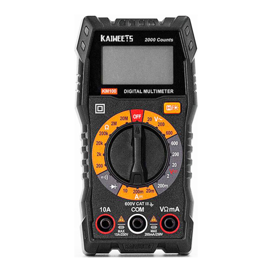
Page 6: Meter Diagram
Meter Diagram... -
Page 7: Production Information
Production Information Symbol Meaning AC (Alternating Current) DC (Direct Current) Continuity Diode Test Earth Ground Fuse Double Insulated Warning: Important Information Class III measurement is suitable for testing measuring circuits CAT. III connected to the distribution part of low voltage power supply devices... -
Page 8: Button Functions
Button Functions Use this switch to select the desired function and range for measurement. Press this button to lock the measurement results, press again to cancel it. Long press to turn on the backlight, long press again to turn off it. Plug the black test lead into this terminal. -
Page 9: Auto Power Off
Auto Power Off After turn on the meter, “ ” icon shows on display, it means the meter will auto power off after 15 minutes without operation, press any key to restore the working state of the instrument. Long press “ ”... -
Page 10: Dc Current Measurement
voltage to avoid electric shock or personal injury. Measure the known voltage or current before use to ensure that the instrument functions well. DC current measurement 1. Disconnect the circuit to be tested; 2. Turn the knob to “A⎓ ” and select the appropriate range;... -
Page 11: Resistance Measurement
the circuit without a load to measure. 5. Read the measurement result on display. If “OL” is displayed, it is out of range, select higher range. WARNING Pay special attention to safety when measuring high voltage to avoid electric shock or personal injury. -
Page 12: Continuity Measurement
NOTE: If the measured value is equal to the nominal resistance of the resistor or within the range of error, the resistor works correctly; If there is a large deviation between the nominal resistance and the resistance, the resistor is damaged;... -
Page 13: Diode Measurement
are connected normally, the buzzer will sound continuously; 5. Contact the probe to the measured circuit, measure the resistance; 6. If the resistance or circuit of the measured resistance is less than 50Ω, the built-in beep will sound and the value will be displayed on the LCD screen;... - Page 14 diode and the black test lead to the negative end, a beep sounds if connected the diode normally. Note: Generally the positive end of the diode is the longer one. 4. Read the result on the LCD display; 5. If there is no reading, switch the test leads to the opposite ends of the diode and measure again.
-
Page 15: Technical Specifications
Technical Specifications CAT.III 600V Pollution level:2 Altitude < 2000m Working environment: 0~40°C Environmental conditions (<80% RH, <10°C non condensing). Storage environment::-10~60°C (<70% RH, remove the battery). Temperature 0.1 accuracy/°C coefficient (<18°C or >28°C) MAX. Voltage 600V Fuse mA:F200mA/250V fuse protection 10A:F10A/250V fuse Sampling rate About 3 times/second... -
Page 16: Accuracy Specifications
Accuracy Specifications The accuracy is applicable within one year after the calibration. Reference condition: Environment temperature: 18°C to 28°C; Relative humidity: ≤80% Accuracy: ( reading + word) DC Voltage Range Resolution Accuracy 200mV 0.1mV 0.001V 0.01V ±(1.0% reading+5) 200V 0.1V 600V... -
Page 17: Ac Voltage
AC Voltage Range Resolution Accuracy 0.01V 200V 0.1V ±(1.0% reading+5) 600V Overload protection: 600V Maximum input voltage: 600V Frequency Response: 40Hz ~ 400Hz DC Current Range Resolution Accuracy 20mA 0.01mA ±(1.5% reading+5) 200mA 0.1mA 0.01A Overload protection: mA: F200mA/250V fuse A: F10A/250V fuse Maximum input current: mA: 200mA, A: 10A When measuring large current, continuous... -
Page 18: Resistance
Resistance Range Resolution Accuracy 200Ω 0.1Ω 2kΩ 0.001kΩ 20kΩ 0.01kΩ ±(1.2% reading+5) 200kΩ 0.1kΩ 2MΩ 0.001MΩ 20MΩ 0.01MΩ Overload protection: 250V Continuity&Diode The resistance is Open circuit voltage is <50, the buzzer about 2V will sound Overload protection:250V Displays the Reverse DC voltage is approximate about 2V... -
Page 19: Replace Battery And Fuse
Replace Battery and Fuse Replace Battery 1. Turn off the power supply of the instrument and remove the probe on the instrument; 2. Remove the screws fixing the battery cover, remove the battery cover; 3. Remove old batteries, replace them with fresh batteries (AAA, 1.5V x 2). -
Page 20: Replace Fuse
Replace Fuse 1. Turn off the power supply of the instrument and remove the probes on the instrument. 2. Remove the screws on the 4 corners fixing the back cover and remove the back cover. 3. Remove the burnt fuse, replace with new fuse of the same specifications (mA :... - Page 21 Three Years Warranty Garantía de 3 ANOS Drei-Jahren-Garantie Tre anni di garanzia Garantie de trois ans 3 年間の保証 support@Kaiweets.com @kaiweetstools...
Need help?
Do you have a question about the KM100 and is the answer not in the manual?
Questions and answers