
Subscribe to Our Youtube Channel
Related Manuals for Kaiweets True RMS 10000 Counts


Summary of Contents for Kaiweets True RMS 10000 Counts
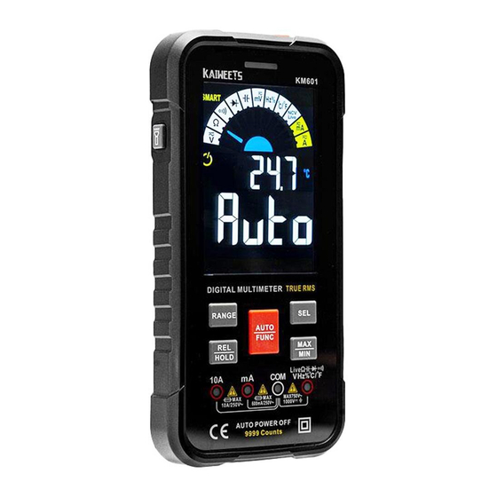
- Page 1 User Manual Smart Digital Multimete KM601 True RMS 10000 Counts November 2021 © 2021 Kaiweets Corporation. All rights reserved. Contact us: support@kaiweets.com...
-
Page 2: Table Of Contents
Contents Safety Information Warnings Product Familiarization Overview Features Display Terminals Making Measurements Warnings SMART (AUTO) Measurement Mode MANUAL Measurement Mode... - Page 3 AC/DC voltage measurement Resistance measurement Continuity test Diode test Capacitance measurement AC/DC mV voltage measurement Frequency/Duty measurement Temperature measurement Non-contact AC voltage detection Live wire detecting Ampere (A) current measurement mA current measurement Maintenance Cleaning...
- Page 4 Install Batteries Replace Fuses DC voltage AC/DC current Diode/ Continuity Resistance Frequency/Duty 3 years Warranty...
-
Page 5: Safety Information
Safety Information Warnings • • • • Carefully read all instructions. • • • adapters) for all measurements. •... - Page 6 • • • • terminals. • • • with the circuit. • • indicator shows. Check test lead continuity. •...
- Page 7 Symbols Symbols Symbols Description Description WARNING. RISK OF DANGER. WARNING. HAZARDOUS VOLTAGE. Risk of electric shock. Hazardous Voltage Conforms to European Union directives. Measurement Category II is applicable to test and measuring circuits connected directly to utilization points (socket outlets and similar points) of the low-voltage MAINS installation.
-
Page 8: Product Familiarization
Product Familiarization Overview... -
Page 9: Features
Features Button Button Function Function displayed. Then press again to switch measurement modes; seconds to return to the SMART (auto) mode. - Page 10 *This function is invalid in SMART mode. Then press to select range. return to autoranging. automatically enter the manual range mode. return to normal measurement. *Data hold function is invalid in NCV / Live test. NCV / live. Value measurement. automatically enter the manual range mode.
-
Page 11: Display
Display Symbol Description Symbol Description Symbol Description Voltage Current Low Battery AC ( Alternating Current ) DC (Direct Current) Diode Test Earth Resistance Test Capacitance Test Live Wire Detection Non-contact Voltage Detection Fuse Damaged Fuse Smart Mode Frequency / Duty Ratio Manual Mode... -
Page 12: Terminals
Terminals Jack indication light Input terminal for measuring ac and dc current to 10 A. Common (return) terminal for all measurements. -
Page 13: Making Measurements
Making Measurements Warnings • • • SMART (AUTO) Measurement Mode... - Page 14 Turn on & Ready to use mode.
- Page 15 Smart mode Volts AC Volts DC Resistance Continuity NOTE: • • •...
-
Page 16: Manual Measurement Mode
MANUAL Measurement Mode function from left to right. AC/DC voltage measurement Turn on & Ready to use ( look at page 10) Volts DC Volts AC NOTE: • • • Do not use the AC voltage test function to test DC voltage and vice versa. •... -
Page 17: Resistance Measurement
Resistance measurement Turn on & Ready to use ( look at page 10) indicating the resistance measurement. NOTE: • Do not change the resistance while taking measurements. • •... -
Page 18: Continuity Test
Continuity test Turn on & Ready to use ( look at page 10) value. -
Page 19: Diode Test
Diode test Turn on & Ready to use ( look at page 10) Forward Bias Reverse Bias Open Shorted Good Diode Bad Diode... -
Page 20: Capacitance Measurement
Capacitance measurement Turn on & Ready to use ( look at page 10) indicating capacitance testing. NOTE: • • a high-powered resistor. • •... -
Page 21: Ac/Dc Mv Voltage Measurement
AC/DC mV voltage measurement Turn on & Ready to use ( look at page 10) Volts DC mV indicating AC voltage measurement. Volts AC mV NOTE: • • • Do not use the AC voltage test function to test DC voltage and vice versa. •... -
Page 22: Frequency/Duty Measurement
Frequency/Duty measurement Turn on & Ready to use ( look at page 10) -
Page 23: Temperature Measurement
Temperature measurement Turn on & Ready to use ( look at page 10) NOTE:... -
Page 24: Non-Contact Ac Voltage Detection
Non-contact AC voltage detection Turn on & Ready to use ( look at page 10) indicating the NCV testing. displayed on the screen. -
Page 25: Live Wire Detecting
Live wire detecting Turn on & Ready to use ( look at page 10) screen. - Page 26 When the Meter detects When the meter detects on the screen. This means displayed on the screen. please test again after full connection.
-
Page 27: Ampere (A) Current Measurement
Ampere (A) current measurement Turn on & Ready to use ( look at page 10) measurement. indicating of AC current measurement. - Page 28 NOTE: • screen. • • The meter will turn on the current testing function when you insert the red test • function correctly. •...
-
Page 29: Ma Current Measurement
mA current measurement Turn on & Ready to use ( look at page 10) measurement. indicating of AC current measurement. - Page 30 NOTE: • screen. • LEAD • The meter will turn on the current testing function when you insert the red test • function correctly. •...
-
Page 31: Maintenance
Maintenance Cleaning Install Batteries... - Page 32 Remove the screw under the flashlight and remove the...
-
Page 33: Replace Fuses
Cleaning change the fuses. To avoid shock, injury, or damage to the Meter: • •... - Page 34 Remove the screw under the flashlight and remove the remove the cover. loaded into the fuse clip and clamped tightly.
- Page 35 Display Counts Power Sampling Speed Weight 3 Times / Second LCD Dimensions Dimensions Range Selection Auto range Environmental conditions Range Selection Automatically MAX. Voltage between terminals and earth ground Displayed Fuse protection Range Selection Work Environment Low Battery Indication Storage Temperature Damaged Fuse Indication Jack Indication...
-
Page 36: Dc Voltage
DC voltage AC voltage Range Resolution Accuracy Range Resolution Accuracy 0.01mV 0.01mV 0.1mV 0.1mV Input Impedance: Input Impedance: 0.001V 0.001V Frequency Response: 0.01V 0.01V 0.1V 0.1V... -
Page 37: Ac/Dc Current
AC/DC current Capacitance Range Resolution Accuracy Range Resolution Accuracy 9.999mA 0.001mA 9.999nF 0.001nF ±(0.8%+3) 99.99mA 0.01mA 99.99nF 0.01nF 600.0mA 0.1mA 999.9nF 0.1nF ±(4.0%+3) 0.001μF ±(1.2%+3) 9.999A 0.001A 9.999μF 99.99μF 0.01μF Overload protection: 999.9μF 0.1μF mA : F600mA/250V fuse 10A: F10A / 250V fuse 9.999mF 0.001mF Frequency Response:40Hz~1kHz;... -
Page 38: Diode/ Continuity
Diode/ Continuity Display diode voltage drop <Approx. 50: Buzzer will sound and the indicator light will be on. Resistance Range Resolution Accuracy 999.9Ω 0.1Ω 9.999KΩ 0.001 KΩ 99.99 KΩ 0.01 KΩ ±(1.0%+5) 999.9 KΩ 0.1 KΩ 9.999MΩ 0.001 MΩ ±(2.0%+10) 99.99 MΩ... -
Page 39: Frequency/Duty
Frequency/Duty Temperature Range Resolution Accuracy Range Accuracy 9.999Hz 0.001Hz -40℃ ~ 0℃ ±5.0% or ±3℃ ℃ 99.99Hz 0.01Hz 0℃ ~400℃ ±1.0% or ±2℃ 999.9Hz 0.1Hz 400℃ ~1000℃ ±2.0% -40 ℉ ~32 ℉ ±5.0% or ±6 ℉ 9.999KHz 0.001KHz ±(1.0%+3) ℉ 32 ℉... -
Page 40: Years Warranty
3 years Warranty years from the date of purchase provided that: • • • • support@kaiweets.com.
Need help?
Do you have a question about the True RMS 10000 Counts and is the answer not in the manual?
Questions and answers