Advertisement
- 1 Product Overview
- 2 Product Description
-
3
Start Measurement
- 3.1 Warning
- 3.2 SMART (AUTO) Measurement Mode
- 3.3 Tum on & Reedy to use
- 3.4 Smart mode
-
3.5
MANUAL Measurement Mode
- 3.5.1 AC/DC voltage measurement
- 3.5.2 Resistance measurement
- 3.5.3 Continuity test
- 3.5.4 Diode test
- 3.5.5 Good Diode
- 3.5.6 Bad Diode
- 3.5.7 Capacitance measurement
- 3.5.8 AC/DC mV voltage measurement
- 3.5.9 Frequency/Duty measurement
- 3.5.10 Temperature measurement
- 3.5.11 Non-contact AC voltage detection
- 3.5.12 Live wire detecting
- 3.5.13 Ampere (A) current measurement
- 3.5.14 mA current measurement
- 4 Maintenance
- 5 Specifications
- 6 Safety Information
- 7 Documents / Resources
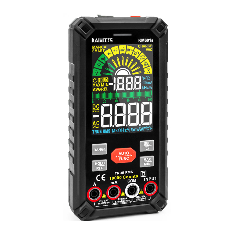
Product Overview

- Charge Jack
- NCV Sensor
- Power Button
- Alarm Indication Light
- LCD Display (colorful)
- Function Buttons
- A Jack
- mA Jack
- COM Jack
- INPUT Jack
- Flashlight
Product Description
Safety symbol meaning
| Symbols | Description | Symbols | Description |
 | WARNING. RISK OF DANGER. |  | WARNING-RISK OF ELECTRIC SHOCK. |
 | Hazardous Voltage |  | Conforms to European Union directives |
| CAT Il | Suitable for testing circuits directly connected to power points (sockets and similarities) of low voltage power installations. | ||
| CAT Ill | Suitable for measuring circuits connected to the distribution part of low voltage power supply devices in building. | ||
| CAT IV | Suitable for measuring circuits connected to the power supply of low voltage power installations in buildings. | ||
Function Buttons


Display

Terminals Introduction

- Jack indication light
When switching to other functions the light above the corresponding jack will flash for users to insert the right test leads to the right jack. - Input terminal for measuring ac and dc current to 10A.
- Input terminal for measuring ac and dc current to 630mA.
- Common (return) terminal for all measurements.
- Input terminal for measuring other functions, like voltage, continuity, resistance, capacitance, frequency and testing diodes.
Start Measurement
Warning
- Do not measure voltages higher than DC1000V or AC750V, which can damage the meter
![shock hazard]() Pay attention to safety when measuring high voltage to avoid electric shock or personal injury
Pay attention to safety when measuring high voltage to avoid electric shock or personal injury- Before use, test the known voltage or current With the meter to make sure the meter is in good function
SMART (AUTO) Measurement Mode
The Meter defaults to SMART mode. In the SMART mode, the meter can test DC voltage, AC voltage, resistance, continuity, it selects the range with the best resolution automatically.
Tum on & Reedy to use
- Long press the '
![]() ' button for about 2 seconds to turn on the meter, '
' button for about 2 seconds to turn on the meter, ' ![]() ' will be displayed on the screen, and the pointer will swing by itself, indicating the SMART mode.
' will be displayed on the screen, and the pointer will swing by itself, indicating the SMART mode. - Insert the red probe into 'INPUT' jack and the black probe into the 'COM' jack.
- Make the red test lead and the black test lead touch each other to check whether they are normal. The buzzer will beep and the indicator light will be on if normal. use the continuity function as a fast, convenient method to check for opens and shorts.
 ' button for about 2 seconds to turn on the meter, '
  ' will be displayed on the screen, and the pointer will swing by itself, indicating the SMART mode.
Smart mode
Connect the test leads with both ends of the circuit or resistance, the Meter automatically selects measurement based on the input.
NOTE:
- When measuring AC voltage, the frequency will be displayed, and when measuring other settings, the ambient temperature will be displayed on the screen.
- When measuring resistance, if the resistance value is less than 500, the meter will beep and the indicator will light up.
- The minimum measurable voltage in SMART mode is 0.5V AC; 0.8V DC.
MANUAL Measurement Mode
The Meter defaults to SMART mode. In the SMART mode, press the '  ', button to switch to manual mode and select function.
AC/DC voltage measurement
- Press the '
![]() ' button to '
' button to ' ![]() ' gear, '
' gear, ' ![]() ' signal and 'V' signal will be displayed on the screen, indicating DC voltage measurement.
' signal and 'V' signal will be displayed on the screen, indicating DC voltage measurement. - Press the '
![]() ' button, signal '
' button, signal ' ![]() ' and signal 'V' will be displayed on the screen, indicating AC voltage measurement.
' and signal 'V' will be displayed on the screen, indicating AC voltage measurement. - Insert the red probe into 'INPUT' jack and the black probe into the 'COM' jack.
- Touch the meter probe to both ends Of the power supply under test,
- When measuring AC voltage, the frequency is displayed at the same time otherwise the ambient temperature is displayed.
- Read the measurement results from the display.
 ' gear, '
  ' signal and 'V' signal will be displayed on the screen, indicating DC voltage measurement.
 ' button, signal '
  ' and signal 'V' will be displayed on the screen, indicating AC voltage measurement.
NOTE:
- When measuring AC voltage, the frequency will be displayed,
- When measuring DC voltage, the ambient temperature will be displayed on the screen.
- Do not use the AC voltage test function to test DC voltage and vice versa.
- Do not measure voltage exceeding 1000V DC or 750V AC to avoid damage to the meter,
Resistance measurement
- Press '
![]() ' button to select '
' button to select ' ![]() ' gear: '
' gear: ' ![]() ' signal will be displayed on the screen, indicating the resistance measurement.
' signal will be displayed on the screen, indicating the resistance measurement. - Insert the red probe into 'INPUT' jack and the black probe into the 'COM' jack.
- Touch the meter probe to both ends of the resistance under test.
- Read the measurement results from the display.
 ' gear: '
  ' signal will be displayed on the screen, indicating the resistance measurement.
NOTE:
- Do not change the resistance while taking measurements.
- Do not test parallel circuits. The accuracy of the measurement will be affected, and the results may not be accurate.
- Do not directly measure the internal resistance of micrometers, galvanometers, batteries, and other instruments.
Continuity test
- Press '
![]() ' button to '
' button to ' ![]() ' gear, indicating the continuity measurement.
' gear, indicating the continuity measurement. - Connect the test leads to both ends of the circuit under test.
- Insert the red probe into 'INPUT' jack and the black probe into the 'COM' jack.
- Contact the probe With both ends Of the measured resistance or circuit.
- When the resistance value is less than about 50Q, the buzzer sounds.
- Reed the measurement results from the display.
 ' gear, indicating the continuity measurement.
NOTE: If the resistance of the circuit or resistor under test is less than 500 and the circuit is on position, the buzzer will beep and an indicator light will light up, and the screen will display the measured resistance value.
Diode test
- Press '
![]() ' button to '
' button to ' ![]() ' gear, indicating the diode testing.
' gear, indicating the diode testing. - Insert the red probe into 'INPUT' jack and the black probe into the 'COM' jack,
- Connect red test lead with the positive polarity of the diode, black test lead with the negative polarity.
- If the test leads are connected reversely with the diode polarity, '
![]() ' will be displayed on the screen.
' will be displayed on the screen. - Read the measurement results from the display,
 ' gear, indicating the diode testing.
 ' will be displayed on the screen.
Good Diode
There will be two situations

When the meter probe is properly connected

When the meter probe is incorrectly connected
Bad Diode
There will be two situations

When the meter probe is properly connected

When the meter probe is incorrectly connected
Capacitance measurement
- Press '
![]() ' button to '
' button to ' ![]() ' gear, 'nF' signal will be displayed on the screen, indicating capacitance testing.
' gear, 'nF' signal will be displayed on the screen, indicating capacitance testing. - Insert the red probe into 'INPUT' jack and the black probe into the 'COM' jack.
- Touch the meter probe to both ends of the capacitor under test.
- Read the measurement results from the display.
 ' button to '
  ' gear, 'nF' signal will be displayed on the screen, indicating capacitance testing.
NOTE:
- If the measured value is significantly different from the value marked on the capacitor, the capacitor is damaged.
- Before measuring the capacitor, discharge the capacitor to avoid damage to the Meter. Do so by connecting the capacitor to a high-powered resistor.
- Discharge the capacitor after measurement to avoid any potential safety hazards.
- If the capacitance is large, it may take a long time for the reading to stabilize.
AC/DC mV voltage measurement
- Press the '
![]() ' button to '
' button to ' ![]() ' setting, '
' setting, ' ![]() ' signal and 'mV' signal will be displayed on the screen, indicating DC mV voltage measurement.
' signal and 'mV' signal will be displayed on the screen, indicating DC mV voltage measurement. - Press the '
![]() ' button, '
' button, ' ![]() ' signal and 'mV' signal will be displayed on the screen, indicating AC mV voltage measurement.
' signal and 'mV' signal will be displayed on the screen, indicating AC mV voltage measurement. - Insert the red probe into 'INPUT' jack and the black probe into the 'COM' jack.
- Touch the probe with both ends of the measured power supply.
- When measuring AC voltage, the frequency is displayed at the same time; otherwise, the ambient temperature is displayed.
- Read the results from the display.
 ' setting, '
  ' signal and 'mV' signal will be displayed on the screen, indicating DC mV voltage measurement.
 ' button, '
  ' signal and 'mV' signal will be displayed on the screen, indicating AC mV voltage measurement.
NOTE:
- When measuring AC voltage, the frequency will be displayed.
- When measuring DC voltage, the ambient temperature will be displayed on the screen.
- Do not use the AC voltage test function to test DC voltage and vice versa.
- Do not measure voltage exceeding 1000V DC or 750V AC to avoid damage to the meter.
Frequency/Duty measurement
- Press the '
![]() ' button to 'Hz%' setting, 'Hz' signal and '%' signal will be displayed on the screen, indicating Frequency/Duty Ratio testing.
' button to 'Hz%' setting, 'Hz' signal and '%' signal will be displayed on the screen, indicating Frequency/Duty Ratio testing. - Insert the red probe into 'INPUT' jack and the black probe into the 'COM' jack.
- Touch the probe with both ends of the measured power supply.
- Read the results from the display.
Temperature measurement
- Insert the positive pole of the K-type thermocouple into the 'Input' jack and the negative pole into the 'COM' jack.
- Press the '
![]() ' button to '
' button to ' ![]() ', '°C' signal and '°F' signal will be displayed on the screen, indicating temperature testing,
', '°C' signal and '°F' signal will be displayed on the screen, indicating temperature testing, - Touch the end of the K-Type thermocouple to the object being measured. The reading may take few seconds to be stable.
 ', '°C' signal and '°F' signal will be displayed on the screen, indicating temperature testing,
NOTE:
When the K-Type thermocouple does not in contact with the object under test, it will read the ambient temperature.
Non-contact AC voltage detection
- Press the '
![]() ' button to '
' button to ' ![]() ', setting, 'NCV' signal will be displayed on the screen, indicating the NCV testing.
', setting, 'NCV' signal will be displayed on the screen, indicating the NCV testing. - Place the NCV probe closer to the point to be tested gradually,
- When the indicator glows and the unit beeps, you know there is voltage present.
 ', setting, 'NCV' signal will be displayed on the screen, indicating the NCV testing.
When the meter detects a weak signal, the green indicator will light up, the buzzer will beep in a slow tone, and '--L' will be displayed on the screen.
When the meter detects a strong signal, the red indicator will light up, the buzzer will beep in a fast tone, and '--H' will be displayed on the screen.
Live wire detecting
- Press the '
![]() ' button to '
' button to ' ![]() ' setting, 'NCV' signal will be displayed on the screen.
' setting, 'NCV' signal will be displayed on the screen. - Press the '
![]() ' button to display the 'LIVE' symbol. Insert the red probe into the 'INPUT' jack and remove the black probe.
' button to display the 'LIVE' symbol. Insert the red probe into the 'INPUT' jack and remove the black probe. - Touch the object under test with the red test lead point.
 ' setting, 'NCV' signal will be displayed on the screen.
 ' button to display the 'LIVE' symbol. Insert the red probe into the 'INPUT' jack and remove the black probe.
NOTE:
- When the indicator light lights up that means the measured position for the fire line, please be careful
- When the Meter detects a weak signal, the green indicator will light up, the buzzer will beep in a slow tone, and '--L' will be displayed on the screen. This means the test leads may not be fully connected to the socket, please test again after full connection.
- When the meter detects a strong signal, the red indicator will light up, the buzzer will beep in a fest tone, and '--H' will be displayed on the screen.
Ampere (A) current measurement
- Insert the red probe into the 'A' jack and the black probe into the 'COM' jack, The Meter will automatically adjust to the '
![]() ' gear. 'DC' signal and 'A' signal will be displayed on the screen, indicating DC current measurement.
' gear. 'DC' signal and 'A' signal will be displayed on the screen, indicating DC current measurement. - Press the '
![]() ' button, 'A' signal and 'AC' signal will be displayed on the screen, indicating of AC current measurement.
' button, 'A' signal and 'AC' signal will be displayed on the screen, indicating of AC current measurement.
 ' gear. 'DC' signal and 'A' signal will be displayed on the screen, indicating DC current measurement.
 ' button, 'A' signal and 'AC' signal will be displayed on the screen, indicating of AC current measurement.
NOTE:
- When measuring AC current, the frequency will be displayed, and when measuring DC current, the ambient temperature will be displayed on the screen.
- 'LEAD' signal will be displayed on the screen and the indicator light will turn red when the test leads are connected incorrectly, please insert the red test lead into 'A' jack.
- The meter will turn on the current testing function when you insert the red test lead into 'A' Jack and the black test lead into 'COM' jack in any mode. For safety, users cannot press the '
![]() ' button to switch the functions.
' button to switch the functions. - The meter will beep regularly to remind users to use the current testing function correctly. Do not measure current >10A in this gear, in case of the 10A fuse burnt.
mA current measurement
- Insert the red probe into the 'mA' jack and the black probe into the 'COM' jack. The meter will automatically adjust to the '
![]() ' gear. 'DC' signal and 'mA' signal will be displayed on the screen, indicating DC current measurement.
' gear. 'DC' signal and 'mA' signal will be displayed on the screen, indicating DC current measurement. - Press the '
![]() ' button, 'mA' signal and 'AC' signal will be displayed on the screen, indicating of AC current measurement.
' button, 'mA' signal and 'AC' signal will be displayed on the screen, indicating of AC current measurement.
 ' gear. 'DC' signal and 'mA' signal will be displayed on the screen, indicating DC current measurement.
 ' button, 'mA' signal and 'AC' signal will be displayed on the screen, indicating of AC current measurement.
NOTE:
- When measuring AC current, the frequency will be displayed, and when measuring DC current, the ambient temperature will be displayed on the screen.
- 'LEAD' signal will be displayed on the screen and the indicator light will turn red when the test leads are connected incorrectly, please insert the red test lead into 'mA' jack.
- The meter will turn on the current testing function when you insert red test lead into 'mA' jack and black test lead into 'COM' jack in any mode. For safety, users cannot press the '
![]() ' button to switch the functions.
' button to switch the functions. - The meter will beep regularly to remind users to use the current testing function correctly. Do not measure current > 630mA in this gear, in case of the mA fuse burnt.
Maintenance
Cleaning
Turn off the power to the Meter and remove the test leads.
Wipe the case with a damp cloth and mild detergent. Dirt or moisture in the terminals can affect readings.
Replace Fuses
'  ' signal will be displayed on the screen when the fuses are blown, current testing function is not working, then please change the fuses.
- Remove test leads from the Meter before opening the case.
- Remove the screws below the shelf,
- Replace the fuse with the same size as described above.
- Close the lid and tighten the screws.
- mA: F630mA/250V fuse;
Size: Φ6*32mm - A: F10A/250V fuse;
Size: Φ6*32mm
![]()

Specifications

Accuracy Specifications
Accuracy is specified for 1 year after calibration, at operating temperatures of 18°C to 28°C, with relative humidity at 0%to 80%.
Accuracy±([%of Reading]+[Counts])

DC voltage

AC voltage

AC/DC current

Capacitance

Diode/Continuity

Resistance

Frequency/Duty

Temperature
Safety Information
The multimeter conforms to IEC61010-1 CAT.III 1000V, CAT.IV 600V over-voltage safety standards and pollution level 2.
A warning identifies conditions and procedures that are dangerous to the user.
Warnings: Read First
To avoid possible electric shock or personal injury, please obey the following instructions:
![shock hazard]() Do not test voltage beyond 60VDC, 30VAC RMS, or 42V peak. Or there is a risk of electric shock,
Do not test voltage beyond 60VDC, 30VAC RMS, or 42V peak. Or there is a risk of electric shock,- Do not measure voltages higher than the rated value between terminals or between terminals and ground,
- Check that the meter is working properly by measuring a known voltage, and do not use it again if it is not normal or has been damaged.
- Before using the meter, check the meter case for cracks or damaged plastic parts, and if so, do not use it again.
- The meter should only be used with the meter pen provided to comply with the safety standards.
- Before using the meter, check the test leads for cracks or damage, If so, replace it with the same type and electrical specifications. When using the meter, hold your fingers behind the finger guard of the probe.
- Use the meter according to the measurement category, voltage, or current rating specified in the meter or manual.
![shock hazard]() Observe local and national safety policies. Wear protective equipment (such as approved rubber gloves, masks, and flame-retardant clothing) to prevent injury from electric shock when dangerous live conductors are exposed.
Observe local and national safety policies. Wear protective equipment (such as approved rubber gloves, masks, and flame-retardant clothing) to prevent injury from electric shock when dangerous live conductors are exposed.- When the low-voltage indicator appears, replace the battery promptly to prevent measurement errors.
- Do not use the meter around explosive gases, vapors, or in a humid environment.
- Remove the meter pen from the meter before opening the case or battery cover.
- Never use the meter with the meter disassembled or the battery cover open.

Documents / ResourcesDownload manual
Here you can download full pdf version of manual, it may contain additional safety instructions, warranty information, FCC rules, etc.
Advertisement


Need help?
Do you have a question about the KM601s and is the answer not in the manual?
Questions and answers