
Related Manuals for MAXIMATOR SLGP 3 Series


Summary of Contents for MAXIMATOR SLGP 3 Series
- Page 1 Air driven liquefied gas pump SLGP 3-..., SLGP 3-3-..., GLGP 5-..., GLGP 5-5-... Installation and operating manual...
- Page 2 Internet: www.maximator.de Warranty and liability: As a general rule, the “General Terms and Conditions” of Maximator GmbH shall apply. These terms and conditions are available at http://www.maximator.de. Warranty and liability claims shall not be accepted if they can be attributed to one or more of the causes mentioned in this manual or explicitly stipulated below: –...
-
Page 3: Table Of Contents
Contents Contents ..........General information . - Page 4 Contents ..........Installing the pump .
- Page 5 Contents ..........10.1 General information .
-
Page 6: General Information
General information Information regarding this manual The air driven liquefied gas pump from Maximator is used for oil-free delivery and compression of refrigerants and other compatible operating fluids. This manual applies to the following types of air driven pumps: SLGP 3-..., SLGP 3-3..., GLGP 5- ..., GLGP 5-5-... -
Page 7: Rating Plate
General information Rating plate The rating plate is located on the drive unit of the pump and contains the follow- ing specifications: Fig. 1-1 Liquefied gas pump rating plate Max. permitted operating pres- Serial number sure Pressure ratio Air driven liquefied gas pump 10 CE label Type (specifications from the or- 11 Manufacturer contact informa-... -
Page 8: Explanation Of Symbols
General information Explanation of symbols DANGER This combination of symbol and signal word indicates a hazardous situation which - if not avoided - may lead to severe injuries or death. WARNING This combination of symbol and signal word indicates a potentially hazardous sit- uation which - if not avoided - may lead to severe injuries or death. -
Page 9: List Of Abbreviations And Formula Signs Used
General information List of abbreviations and formula signs used Abbreviation Description Fig. Figure Tab. Table max. maximum min. minimum pcs. pieces Number seconds Personal protective equipment ex.) for example EU mark of conformity DGRL EU pressure equipment directive ATEX EU explosion prevention directive Equipment Protection Level Central European Time Tab. -
Page 10: Safety And Protection Measures
Safety and protection measures Safety and protection measures The following sections stipulate the residual risks associated with the product, even when used as intended. In order to reduce the risk of personal injuries and material damage, and to prevent hazardous situations, you must observe the safety information listed in this section and the warnings in all other sections of this manual. -
Page 11: Non Obvious Hazards
Safety and protection measures During assessment, check the following leak points: leak point leak type leak source Comment bleed port Minor release high-pressure On the -FS version, seal, rod seal on the bleed port is drive side equipped with a flame safeguard. -
Page 12: Residual Risks
Safety and protection measures Residual risks 2.5.1 Start-up and shut down When the pneumatic power supply is restored or the operating parameters are modified, the pump can start up unexpectedly. This can lead to severe injuries or death. Assess the risk for the equipment in the risk assessment. There is no command device for safe shut-down (E-stop). -
Page 13: Product Description
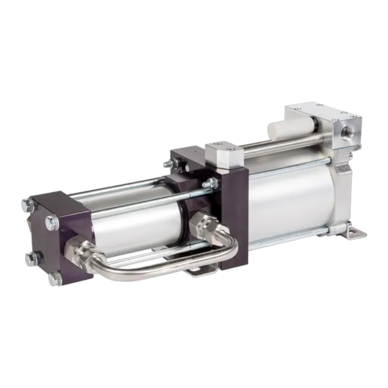
Product description Product description Design and function Design of SLGP 3 and GLGP 5 (air reversal, with control air, double-acting) Air piston Gas inlet High-pressure piston Gas outlet Pilot valve lower cap PL Drive air port Pilot valve top cap Exhaust port Control slide valve Spool valve air supply port... - Page 14 Product description Design of SLGP 3-3 and GLGP 5-5 (air reversal, with control air, two-stage) Air piston Gas inlet High-pressure piston Gas outlet Pilot valve lower cap PL Drive air port Pilot valve top cap Exhaust port Control slide valve Spool valve air supply port Pilot valve air supply port Pilot port...
- Page 15 Product description The spool valve is controlled by two directional valves, the pilot valves (3, 4), which are operated mechanically by the air piston in its stop positions. The pilot valves aerate and vent the operating area of the control slide valve. An equilibrium of forces on the drive and high-pressure side is generated as soon as the stall pressure is reached.
- Page 16 Product description Design of pressure intensifiers SLGP 3-DÜ and GLGP 5-DÜ (double-acting) Air piston Gas inlet High-pressure piston Gas outlet PL1 Drive air port 1 PL2 Drive air port 2 0000000383 - 001 - EN...
- Page 17 Product description Design of pressure intensifiers SLGP 3-3-DÜ and GLGP 5-5-DÜ (two-stage) Air piston Gas inlet High-pressure piston Gas outlet PL1 Drive air port 1 PL2 Drive air port 2 Functional description SLGP 3-DÜ, SLGP 3-3-DÜ, GLGP 5-DÜ, GLGP 5-5-DÜ The operating principle of a liquefied gas pump is similar to that of a pressure in- tensifier.
-
Page 18: Intended Use
Product description Intended use Within their technical limits, liquefied gas pumps are used to deliver and com- press compatible refrigerants and other compatible operating fluids. If the liquefied gas pump bears an ATEX label and comes with a declaration of con- formity, it is designated for use in corresponding potentially explosive areas. -
Page 19: Technical Specifications
Product description Spool valve “V” ventilation port Ventilation and bleeding of the spool valve. The port must not be obstructed. Pilot valve "Y" exhaust port Bleeding of the spool valve actuator chamber. An air pulse escapes here after each stroke. The port must not be obstructed. This port can be used to connect a stroke counter. - Page 20 If you are unsure re- garding the use of a special fluid, please don't hesitate to contact Maximator. The most common operating fluids of the approved safety classes are shown in...
- Page 21 Max. particle size µm a. Maximator pumps generally do not need a compressed air oiler as they are treated with special grease during installation. However, after the first time an oiler is used, the drive flu- id should always be oiled, since the oil washes the special grease out. In case a compressed air oiler is used, the oil must comply with DIN 51524 - ISO VG 32 specifications.
-
Page 22: Dimensions And Weight
The suitability of the drive fluid must be checked. Special materials or drive variants must possibly be used (e.g. drive with exhaust air port line). Maximator will be happy to support you with this. 3.6.2 Dimensions and weight The dimensions and weight of the liquefied gas pump are indicated on the gener- al drawing. -
Page 23: Transport, Packaging And Storage
Transport, packaging and storage Transport, packaging and storage Dimensions and weight The dimensions and weight of the product are indicated in the general drawing. Delivery Scope of delivery Designation Quantity Liquefied gas pump Installation and operating manual including Decla- ration of Incorporation and EU Declaration of Con- formity General drawing Tab. - Page 24 Transport, packaging and storage Maintenance during storage Even under the aforementioned storage conditions, the pump cannot be stored indefinitely. – If in storage for longer than 3 months: Inspect the packaging and the pump for damage on a regular basis. –...
-
Page 25: Installation
Installation Installation Prerequisites for installation Observe the manual and general drawing of the product. In addition, the following conditions must be met: – The product must be free of damage. – The product must be easily accessible from all sides. –... -
Page 26: Exhaust Silencer Installation
Installation 5.3.5 Exhaust silencer installation If the exhaust air connection pipe of the liquefied gas pump is not installed sepa- rately, the enclosed exhaust air silencer must be installed at the corresponding port. Commissioning 5.4.1 Prerequisites for commissioning Observe the manual and general drawing of the product. In addition, the following conditions must be met: –... -
Page 27: Commissioning
Installation 5.4.2 Commissioning WARNING Risk of injury due to extreme temperatures! The surfaces of the product can be very hot or very cold. This can lead to acci- dents resulting in severe injuries or death. ► Before working on the product, please ensure that the product is at ambient temperature. -
Page 28: Operation
Operation Operation Prerequisites for operation Observe the manual and general drawing of the product. In addition, the following conditions must be met: – The product must be free of damage. – The product must be securely attached. – The product is not subject to any vibrations greater than those typically oc- curring in high-pressure systems. -
Page 29: Signs Indicating The Product Is No Longer Safe To Use
Operation Signs indicating the product is no longer safe to use The following signs indicate that the pump is no longer safe to use. In such cases, the pump must be put into a safe state immediately. – Leaking high-pressure seal –... -
Page 30: Maintenance
The individual maintenance activities are described in the following section. Maximator recommends the intervals listed below. These intervals are calculated based on 1,300,000 strokes/year. The required maintenance intervals depend on the system and application. The intervals must be adjusted based on the given conditions of use. - Page 31 Risk of injury due to inappropriate spare parts! Making repairs using inappropriate spare parts can lead to accidents resulting in severe injuries or death. ► Only use spare parts that comply with Maximator specifications. WARNING Risk of injury when handling lubricants! Handling lubricants can lead to accidents resulting in severe or fatal injuries.
-
Page 32: System Inspection
Maintenance 7.2.1 System inspection The following section explains how to check the pump for proper function: Description Qualifications Operating the system Type of mainte- Check nance Interval weekly – Safety goggles – Hearing protection Shut off the fluid outlet and adjust p to a value that is standard for the sys- tem. -
Page 33: Inspect Screws And Connecting Lines
Maintenance Description Prerequisites – The pump is easy to access. – All connections are pressurised. Tools – Torch – Cleaning cloth – Leak detection spray Safety goggles Check connections for leaks. Use leak detection spray. If the inspection does not reveal any abnormalities, it will be safe to contin- ue using the pump. -
Page 34: Cleaning The Pumps
Maintenance 7.2.4 Cleaning the pumps The following section explains how to clean the pump: Description Qualifications Clean pump Type of mainte- Cleaning nance Interval quarterly Prerequisites – The pump is easy to access. – The pump is depressurised. Tools – Cotton cleaning cloth –... -
Page 35: Checking Screw Connections At The Pump And Connecting Elements
Maintenance 7.2.5 Checking screw connections at the pump and connecting elements The following section explains how to inspect the screw fittings on the pump and the connection ports: Description Qualifications Repair and service the pump Type of mainte- Check nance Interval quarterly Prerequisites... -
Page 36: Repairing The Pumps
Maintenance Description Measure leak in the high pressure seal and piston seal of the drive piston via port "Z". Vent p does not drop by more than 10% (holding time 30 s). Set p to approx. 50% of the value from the first step and slowly vent P The pump starts up on its own. -
Page 37: Spare Parts And Consumables
7.2.6 - Leak test If the pump has passed all tests, the repair is complete. Maximator devices can be sent in for repairs to your local Maximator representa- tive. All the necessary details are available on the Maximator website http:// www.maximator.de... -
Page 38: Customer Service
Maintenance Customer service Our customer service is also at your disposal for technical details and repairs: Address Maximator GmbH Ullrichstraße 1-2 99734 Nordhausen Germany Customer service phone +49 3631 9533-5444 Mon. – Thurs.: 06:30 – 16:15 CET Fri.: 06:30 – 14:00 CET... -
Page 39: Troubleshooting
Troubleshooting The following is a list of typical liquefied gas pump faults, their causes, and the ap- propriate solutions. If you experience any other specific or unexpected faults, please notify us at ser- vice@maximator.de Fault Cause of fault Solution The pump does not oper- Friction of the O-rings on –... - Page 40 Troubleshooting Fault Cause of fault Solution The pump operates with- Check valve failure Inspect the check valves out delivering the gas, or and replace if necessary it operates erratically. It does not reach the calcu- lated operating pressure. Operating pressure es- Worn out HP seal or seal Replace seal kit capes through bleed port...
-
Page 41: Removal And Disposal
Shut down the pump. – Depressurise it. – Loosen the fastening screws and connections. – Dismantle the pump. Disposal If the service life has expired: Send the product back to Maximator, postage paid, for proper disposal. 0000000383 - 001 - EN... -
Page 42: Use In Explosion-Prone Zones
Use in explosion-prone zones Use in explosion-prone zones 10.1 General information Pumps bearing an ATEX label and accompanied by a declaration of conformity in accordance with 2014/34/EU are designated for use in potentially explosive areas. They belong to equipment group II, equipment category 2G, explosion group IIB, safety by design. -
Page 43: Temperature Class
Use in explosion-prone zones 11 Equipment protection level (EPL) Gb: Equipment in Group II for explosive zones generate vapours or mist due to mixing of air and gases; can be used in Zone 1 or Zone 2; sufficient protection for normal operation and in case of foreseeable errors. -
Page 44: Operation And Maintenance
Use in explosion-prone zones The liquefied gas pump must not be insulated. If it is insulated, however, the equipment manufacturer must determine the temperature class of the equip- ment accordingly. For the compression of ideal gases, the maximum expected temperature can be calculated using the formula for adiabatic status change: Legend: = input temperature... -
Page 45: Operation With Combustible Operating Fluids
Use in explosion-prone zones 10.4 Operation with combustible operating fluids WARNING Risk of sustaining injury due to explosion! An ignitable gas mixture in the pump may cause explosions. This can lead to acci- dents resulting in severe injuries or death. ►... -
Page 46: Summary Of Ignition Hazards
Summary of ignition hazards Summary of ignition hazards Ignition hazard Cause Protective measure implemented Source of ignition Hot surface Heating by the operating fluid Calculation formula and compression Temperature class definition Insulation prohibited Friction Friction in the drive unit Selection of materials and operating pa- rameters Definition of maintenance intervals Definition of the compressed air quality... - Page 47 Summary of ignition hazards Ignition hazard Cause Protective measure implemented Source of ignition Static Charging of non-conductive Design in accordance with layer thickness electricity layers specifications Static Charging due to powerful Exclusion of powerful charge generating electricity charge generating mecha- mechanisms nisms Adiabatic...
-
Page 48: Appendix
Appendix Appendix The appendix comprises the following documents: – EU Declaration of Conformity – liquefied gas pumps – Declaration of incorporation – liquefied gas pumps – Description of the basic health and safety requirements 0000000383 - 001 - EN... - Page 49 Appendix 0000000383 - 001 - EN...
- Page 50 Appendix 0000000383 - 001 - EN...
- Page 51 Appendix Description of the basic health and safety requirements (Machinery Directive 2006/42/EC, Appendix I) Basic requirement Applicable Met Comment BASIC HEALTH AND SAFETY RE- QUIREMENTS GENERAL INFORMATION 1.1.1 Definitions 1.1.2 Safety integration principles 1.1.3 Materials and products 1.1.4 Lighting 1.1.5 Machine design regarding han- Device corresponds to dling...
- Page 52 Appendix Basic requirement Applicable Met Comment 1.3.3 Risks posed by dropping or eject- ed objects 1.3.4 Risks posed by surfaces, edges Deburring generally re- and corners quired 1.3.5 Risks posed by multiple ma- chines combined 1.3.6 Risks posed by changed usage conditions 1.3.7 Risks posed by movable parts...
- Page 53 Appendix Basic requirement Applicable Met Comment 1.5.7 Explosion assessed separately 1.5.8 Noise depending on installa- tion and application 1.5.9 Vibrations vibrations in conven- tional range 1.5.10 Radiation 1.5.11 Radiation from the outside 1.5.12 Laser radiation 1.5.13 Emission of hazardous materials Release and leakage of and substances operating fluids...
- Page 54 Appendix Basic requirement Applicable Met Comment 1.7.4.1 General guidelines for the for- mulation of the operating manu- 1.7.4.2 Contents of the operating manu- 1.7.4.3 Sales brochures ADDITIONAL BASIC HEALTH AND SAFETY REQUIREMENTS FOR CERTAIN CATEGORIES OF MA- CHINE ADDITIONAL BASIC HEALTH AND SAFETY REQUIREMENTS TO ELIMINATE HAZARDS DUE TO THE MOBILITY OF THE MACHIN-...
- Page 55 Appendix 0000000383 - 001 - EN...
- Page 56 Visit our website at: www.maximator.de 1999.0035 EN 0000000383 - 001 - EN...
Need help?
Do you have a question about the SLGP 3 Series and is the answer not in the manual?
Questions and answers