
Related Manuals for AccuEnergy RIK V


Summary of Contents for AccuEnergy RIK V
- Page 1 RIK V 0-5Vdc/0-10Vdc Rogowski Coil Integrator Users Manual PowerMeterStore 1.800.561.8187 www. Shop for Power Metering products online at:...
- Page 2 The information contained in this document is believed to be accurate at the time of publication, however, Accuenergy assumes no responsibility for any errors which may appear here and reserves the right to make changes without notice. Please ask the local representative for latest product specifications before ordering.
- Page 3 Accuenergy shall not be responsible or liable for any damages caused by improper meter installation and/or operation. Product is protected by reinforced insulation...
-
Page 4: Table Of Contents
Table of Contents Chapter 1: Overview ....................4 1.1 Overview ..........................4 1.2 What's Included ........................4 Chapter 2: Overview ....................6 2.1 Hardware Overview ......................7 2.2 Installation .......................... 7 2.3 Configuration ........................13 2.4 Measurements ..............................14 Appendix: Key Specifications ..................15 SPECIFICATIONS ........................15 PowerMeterStore 1.800.561.8187... - Page 5 RIK V 0-5Vdc/0-10Vdc Rogowski Coil Integrator Chapter 1 1.1 Overview 1.2 What's Included PowerMeterStore 1.800.561.8187 www. Shop for Power Metering products online at:...
-
Page 6: Chapter 1: Overview
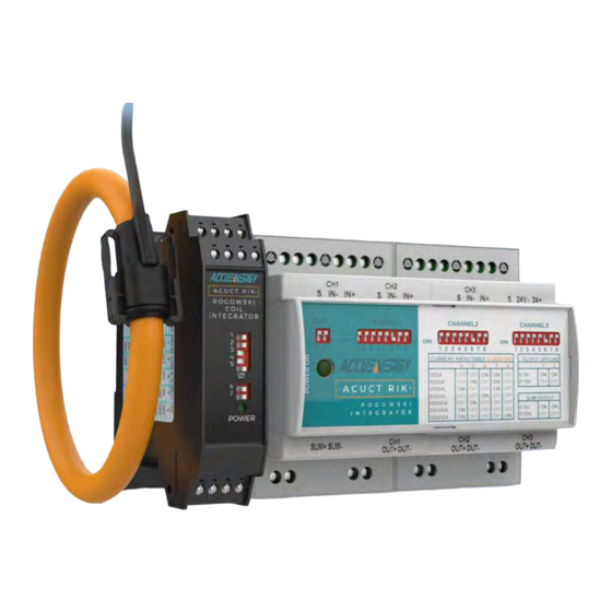
Chapter 1: Overview 1.1 Overview The Rogowski Integrator (RIK V) is designed to provide users with an easy to install, plug and play, retrofit solution that can be used with any power meter or equipment with either 0-5Vdc and 0-10Vdc current input from a Current Transformer(CT). The flexibility of the Rogowski Coil CT's reduces the complexity and allows it use to be used for a variety of applications and configurations where special constraints may limit the use of other CT solutions. - Page 7 Chapter 1: Overview Single Phase Integrator Details: Rogowski Coil Input CT Configurator Three Channels for flexible rope style CT Seven individual field configurable CT input. ratios for each channel 0-5V/0-10V Output Rogowski Coil Three Channels, 0-5V/0-10V Output. CT sizes available from 16-47 inches Power On Light Coil Input Lead Indicates that the RIK is powered up.
-
Page 8: Chapter 2: Overview
RIK V 0-5Vdc/0-10Vdc Rogowski Coil Integrator Chapter 2 2.1 Hardware Overview 2.2 Installation 2.3 Configuration 2.4 Measurements Chapter 2: Overview PowerMeterStore 1.800.561.8187 www. Shop for Power Metering products online at:... -
Page 9: Hardware Overview
2.1 Hardware Overview The RIK V is composed of the integrator and the optional power supply which can all be mounted on a DIN rail along with one or three Rogowski coils. Rogowski coil and power supply sold separately. - Page 10 RIK V 0-5V/0-10V Rogowski Coil Integrator Dimensions: 42.3 Figure 1: Top View 42.3 90.5 Figure 2: Side View V: 1.0.2 Revision Date: Jun 2023 PowerMeterStore 1.800.561.8187 www. Shop for Power Metering products online at:...
- Page 11 Chapter 2: Hardware Overview A-A ( 1 : 1 ) 103.3 Figure 3: Front view 3.5” (90mm) Figure 4: Side view of Power Supply unit V: 1.0.2 Revision Date: Jun 2023 PowerMeterStore 1.800.561.8187 www. Shop for Power Metering products online at:...
- Page 12 0-5V/0-10V Rogowski Coil Integrator Figure 5: Single Phase Integrator The installation of the RIK V integrator requires the user to simply connect the Rogowski coil CT (sold separately) to the integrator and wire the 0-5/0-10V output to the power meter or electrical equipment which will receive the signal.
- Page 13 Chapter 2: Hardware Overview The diagram below illustrates how to connect the integrator. Source 24V- 24V+ 24Vdc Output Power Supply AcuCT RIK Rogowski Integrator 100-240Vac Input Power Supply SUM+ SUM- Out+ Out- Out+ Out- Out+ Out- 100-240Vac-24Vdc Power Supply Load Three Phase Integrator Source brown...
- Page 14 • 'OUT-' is to be connected to the negative input terminal of meter. Power Supply: (Sold Separately) The RIK V requires 24Vdc power to operate. There is a 100-240Vac (50/60Hz) power adapter that is included to provide this power. •...
-
Page 15: Configuration
Chapter 2: Hardware Overview 2.3 Configuration One or three sets of dip switches are used to configure corresponding current ranges with output ratings. When the dip switch is in the up position the dip switch is considered to be Off. When the dip switch is in the down position the dip switch is considered as On. -
Page 16: Measurements
RIK V 0-5V/0-10V Rogowski Coil Integrator Table 3 - Single Phase Integrator Current Ratio Table 500A 1000A 2500A 5000A 10000A 25000A 50000A Output Options 0-5V 0-10V 2.4 Measurements For each current range the integrator will be able to measure the current from 0.5% up to 120% of the rated current. -
Page 17: Appendix: Key Specifications
Chapter 2: Hardware Overview Appendix: Key Specifications SPECIFICATIONS Specifications Measurements Current Measurement Range 2.5A - 60000A Output Current 0-5V/0-10V (Field Configurable) Sensing Range 500A, 1000A, 2500A, 5000A, 10000A, 25000A and 50000A (Field Configurable) Measurement Channels 1 or 3 Channel Frequency 45Hz to 65Hz Accuracy +1% Full Scale Error...
Need help?
Do you have a question about the RIK V and is the answer not in the manual?
Questions and answers