Table of Contents
Advertisement
Quick Links
Advertisement
Table of Contents

Subscribe to Our Youtube Channel
Related Manuals for AccuEnergy AcuDC 241


Summary of Contents for AccuEnergy AcuDC 241
- Page 1 AcuDC 240 Series Power Meter User's Manual...
- Page 3 CopyRight© 2012 V1.01 Accuenergy Tech. Ltd. This manual may not be altered or reproduced in whole or in part by any means without the expressed written consent of Accuenergy. Accuenergy reserves all rights. [ Document #1504E2101 Revision Date: Jul., 2012 ]...
- Page 4 Prior to maintanence and repair, the equipment must be de-energized and grounded. All maintainence work must be performed by qualified, competent accredited professionals. Accuenergy shall not be responsible or liable for any damages or injuries caused by im- proper meter installation and/or operation.
-
Page 5: Table Of Contents
Contents Chapter 1 Introduction ......................1 1.1 Meter Overview ........................2 1.2 Areas of Application.......................3 1.3 AcuDC 240 Series .........................3 Chapter 2 Installation .......................5 2.1 Appearance and Dimensions....................6 2.2 Installation Methods......................7 2.3 Wiring..............................9 Chapter 3 Meter Display and Operation..................23 3.1 Display Panel and Keys......................24 3.2 Metering Data..........................25 3.3 System Parameter Settings....................28 3.4 I/O Parameter Settings......................32... - Page 7 Welcome to AcuDC 240 ! You have purchased an advanced, versatile, multifunction power meter. This meter can work as a remote terminal unit (RTU) that contributes to your system's stability and reliabil- ity. When you open the package, you will find the following items: 1.
-
Page 9: Chapter 1 Introduction
Chapter 1 Introduction 1.1 Meter Overview 1.2 Area of Application 1.3 AcuDC 240 Series... - Page 10 1.1 Meter Overview Powerful Yet Cost-Effective AcuDC 240 series monitors DC voltage, current, power and energy. It supports bi-direc- tional current measurement, and also displays meter running hour and load running hour. Analog Output applies to DCS systems, industrial monitoring and control. AcuDC 240 has a combination of accurate measurement, intelligent multifunction and simple human ma- chine interface.
- Page 11 Metallurgy,Galvanoplastics and Electroanalysis Industries 1.3 AcuDC 240 Series AcuDC 240 series has three products: AcuDC 241, AcuDC 242, AcuDC 243. AcuDC 241 is a voltage meter, only monitors voltage; AcuDC 242 is a current meter, only monitors current; AcuDC 240 is a multifunction meter, monitors voltage, current, power and energy.
-
Page 13: Chapter 2 Installation
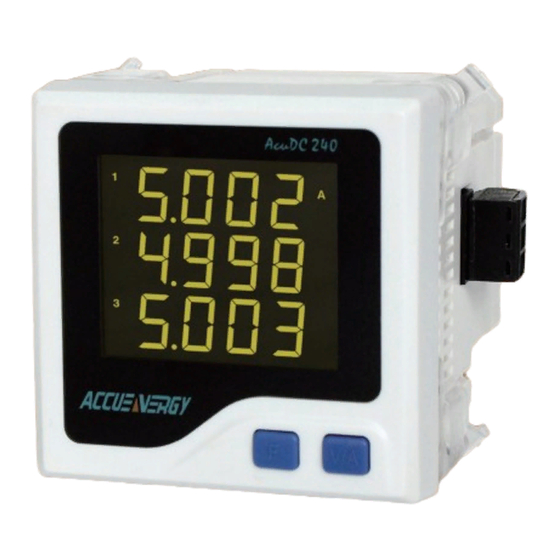
Chapter 2 Installation 2.1 Appearance and Dimensions 2.2 Installation Methods 2.3 Wiring... - Page 14 The installation method is introduced in this chapter. Please read this chapter carefully be- fore beginning installation. 2.1 Appearance and Dimensions 2.1.1 Appearance Ac uD C2 40 Figure 2-1 AcuDC 240 Appearance Part Description Casing High intensity fire resistant engineering plastics ...
-
Page 15: Installation Methods
If a larger temperature will cause damage. range is needed, please contact Accuenergy. Please note it can influence the meter life negatively if the meter operates in extremly high or extremly low temperature environments. AcuDC 240 storage temperature range is -40°C~85°C. - Page 16 3. Location AcuDC 240 series meter should be installed in a dry and dust free environment. Avoid ex- posing meter to excessive heat, radiation and high electrical noise sources. Installation Steps: AcuDC 240 series power meter is generally installed into the switchboard panel. 1.
-
Page 17: Wiring
3. Install clips on the back side of the meter and secure tightly to ensure the meter is af- fixed to the panel. See Figure 2-5. Panel Figure 2-5 Install the clips 2.3 Wiring Terminal Strips There are 3 groups of current terminal strips. There will be another terminal strip if the me- ter is connected with the I/O module. - Page 18 I/O terminal strip (2DI+2AO) DI11 DI12 DI21 DI22 AO1- AO1+ AO2- AO2+ I/O terminal strip (2DI+2RO/2DO) DI11 DI12 DI21 DI22 O11 Communicaton terminal strip Comm Port Figure 2-6 AcuDC 240 terminal strip Safety Earth Connection Before setting up the meter's wiring, please make sure that the DANGER switchgear has an earth ground terminal.
- Page 19 Power Supply AcuDC 240 series meter power supply is 100-240Vac(50/60Hz) or Alert 100-300Vdc,which is universally supported. Please contact us for Make sure the power sup- other voltage options. The meter's typical power consumption is ply meets the standard of very low and can be supplied by an independent source or by the the power supply voltage on the meter's nameplate.
- Page 20 1A FUSE L /+ Power Supply AcuDC 240 Figure 2-9 Power Supply Wiring with EMC filter The wire size for the power supply is AWG16~22 or 0.6~1.5mm Voltage Input AcuDC240 has two voltage input options: Direct Input and Via Hall Sensor. The wire size for the voltage input is AWG16-22 or 0.6-1.5mm .
- Page 21 Current Input Current Wiring Three ways: Direct Input, Via Shunt, Via Hall Effect Sensor Vdc+ Vdc- Current Hall Effect Sensor AcuDC 240 Output External DC Power Load Current Wiring using Current Hall Effect Sensor Figure 2-11 Current Input...
- Page 22 When voltage and current are wired at the same time: Vdc+ Vdc- Vdc+ Vdc- Voltage Hall Effect Sensor Input Output AcuDC 240 AcuDC 240 External DC Power Output Output External DC Power Load Current Hall External DC Power Load Effect Sensor Voltage &...
- Page 23 Note:The load's negative must be connected to meter's current input terminal.Cur- rent output terminal should be connected to the system's negative. The load is serially connected to the meter or the shunt. The current input wire size is AWG15-16 or 1.5-2.5mm or equivalent resistance wire.
- Page 24 circuit (the last meter of the chain) if the communication quality is distorted. If a RS485 converter is used, it should support optical isolation and surge protection. Digital Input AcuDC 240 optional I/O module is equipped with two dry contact digital inputs. The termi- nals are DI11(17), DI12(18),DI21(19),DI22(20).
- Page 25 output, please specify when ordering. Vout Vout AO + AcuDC 240 AcuDC 240 AO - AO - Current Output Voltage Output Figure 2-14 Analog Output Analog Output can be used for scaling current, voltage, power. The output type is fixed (0-20mA/4-20mA or 0-5V/1-5V), the output range can be configured.
- Page 26 Measured Value × 100%- Lower Limit Full Range Value × 1:Voltage Type 0~5V:AO= Upper Limit Lower Limit Measured Value × 100%- Lower Limit Full Range Value × 1~5V:AO=1+ Lower Limit Upper Limit Measured Value × 100%- Lower Limit Full Range Value ×...
- Page 27 Power Table 2-3 AO parameter code The following are a few examples: (1)AO is voltage type: Measured Value × 100% Lower Limit × 100% Full Range Value × × Upper Limit Lower Limit Set AO parameter as Voltage, Upper Limit is 100%, Lower Limit is 0%, Full Range Value is 600V.
- Page 28 (4)AO is current type: Set AO parameter as Power, Upper Limit is ±100%, Lower Limit is 0%, Full Range Value is 12kW. When the Measured Value is -6kW, AO is: -(Measured Value) × 100% Lower Limit 100% × Full Range Value ×...
- Page 29 Power Supply Medium Relay AC /DC Medium Relay Coil AcuDC 24 0 Figure 2-15 Relay Output The wire size for the relay output circuit loop is AWG22~16or0.5~1.3mm The relay outputs have three options. One is Latch Mode: the output is "ON" and "OFF" state;...
- Page 30 3. Set the threshold value. 4. Set the delay time(the minimum unit is second, the range is 0-255s) Example: Alarm condition is set for current larger than 10A. In a delay time of 15s, send alarm signal via RO1. Steps: 1.
-
Page 31: Chapter 3 Meter Display And Operation
Chapter 3 Meter Display and Operation 3.1 Display Panel and Keys 3.2 Metering Data 3.3 System Parameter Settings 3.4 I/O Parameter Settings 3.5 Meter Information Display... -
Page 32: Display Panel And Keys
Operational details of the meter will be described in this chapter. This includes viewing real-time metering data and setting parameters using diff erent key combinations. 3.1 Display Panel and Keys The front of the AcuDC 240 series meter consists of an LCD screen and two control keys. All display segments are shown in Fig. -
Page 33: Metering Data
umber isplay Description Displays data of voltage, current, power, energy. kV,kA,kW,MW,Hz,kvar, Mvar, k VA , MVA , k W h Data unit. ,kvarh,kVAh No icon: no communication; One icon: query sent Communication Two icons: query sent and response received Settings Mode Indicates the meter is in Settings Mode. - Page 34 Voltage Meter Display For AcuDC 241, it only displays voltage. U=220.2V. Figure 3-2 Voltage Display Current Meter Display For AcuDC 242, it only displays current. I=49.99A. Figure 3-3 Current Display Multifunction Meter Display For AcuDC 243, the screen displays voltage, current and power.
- Page 35 screen:Import Energy. E_imp=68.32kWh. Press "V/A" to scroll to the 2 screen. Figure 3-5 Import Energy Display screen:Export Energy. E_exp=25.58kWh. Press "V/A" to scroll to the 3 screen. Figure 3-6 Export Energy Display screen:Total Energy. E_total=93.90kWh. Press "V/A" to scroll to the 4 screen.
-
Page 36: System Parameter Settings
3.3 System Parameter Settings Pressing “F” and “V/A” simultaneously will activate the parameter setting mode. In parameter setting mode, “F” key is used to increase value by one for the flashing digit. "V/A" key is used to confirm the flashing digit and move the cursor. At the last digit of the parameter, pressing "V/A"... - Page 37 screen: Communication address setup. It is used to set communication address, which can be any integer 1-247. The left figure shows the address is 1. To change: press "F" to add one to the flashing digit. Press "V/A" to confirm and move the flashing digit.
- Page 38 screen: full range current setting. Range: 20-50000, unit is A. Press “F” and “V/A”to edit the vaule. Press “V/A”at the last digit to go to the next screen. Note: only indirect current wiring has this screen. Figure 3-14 full range current setting screen: full range shunt setting.
- Page 39 screen: voltage hall effect sensor setting. Two modes:0:0 - ±5V;1:0 - ±4V. Press "F" key to select. Press “V/A” to go to the next screen. Note: only the voltage wiring via voltage hall effect sensor has the above two screens. Figure 3-18 voltage hall effect sensor setting screen: clear Energy.
-
Page 40: I/O Parameter Settings
By now the parameter settings are completed. Pressing “F” and “V/A” simultaneously will exit system parameter settings mode and return to the metering data mode. 3.4 I/O Parameter Settings For meters with I/O module, under system parameter settings mode, hold “F” key for 3 sec- onds to enter I/O settings mode. - Page 41 screen: AO1 parameter setting. Three options: 0 , volage; 1, current ; 2 , power. Press "F" key to select. Press “V/A” to go to the next screen. The figure shows AO1 is set as current. Note: 241 and 242 meter do not have this screen. AO1 is set as what is being measured.
- Page 42 screen: AO2 parameter setting.Three options: 0 , volage ; 1 , current ; 2 , power . Press "F" key to select. Press “V/A” to confirm and go to the next screen. The figure shows AO2 is set as voltage. Note: 241 and 242 meter do not have this screen.
- Page 43 screen: RO1 mode. Three modes : 0 , Latch ; 1 , Momentary ; 2 , Alarm . Press "F" key to select. Press “V/A” to confirm and go to the next screen. Figure 3-28 RO1 mode setting screen: when RO1 mode is set as Momentary mode, the 2 screen is momentary delay time.
- Page 44 screen: RO1 alarm threshold setting. The threshold setting range is the same as the measurement range. Voltage: 0-1200,Current: 0-50000,Power 0-60000. Press "F” and “V/ A”to edit the vaule. Press “V/A to confirm and go to the next screen. Figure 3-32 RO1 alarm threshold setting screen: RO1 alarm delay time 0-255,unit: second.
- Page 45 screen: RO2 alarm parameter when RO is set as Alarm mode. 0,no alarm;1,voltage;2,current;3,power. Press "F" key to select. Press “V/A” to confirm and go to the next screen. Figure 3-36 RO2 alarm parameter setting screen:RO2 alarm inequality setting. 1, larger than; 0,smaller than.
-
Page 46: Meter Information Display
screen: RO2 alarm delay time 0-255,unit: second. The left figure shows the delay time is 15. When the alarm condition is met, after 15 seconds, alarm will be triggered. Or when the alarm condition is no longer met, after 15 seconds, the alarm will be restored. - Page 47 In the metering data mode, hold "V/A" key for 3 seconds to en- ter meter serial number display mode. It displays the last 8 digits of the meter serial number.The left figure shows the meter serial number is DC12012501. Press“V/A” key to return to the metering data mode. Figure 3-42 meter serial number display...
-
Page 49: Chapter 4 Communications
Chapter 4 Communication 4.1 MODBUS-RTU Protocol 4.2 Communication Format 4.3 Communication Address Table... - Page 50 This chapter will mainly discuss how to operate the meter via communication port using software. To master this chapter, you should be familiar with Modbus and read other chapters of this manual to make sure that you have a good understanding of the functions and applications of this product.
- Page 51 2. Modbus Protocol 2.1 Frame When data frame reaches the terminal unit,the unit removes the data frame's header, reads the data, if there is no error, then it implements the data's task. Afterwards, the unit puts its own data with the acquired header, and sends back the frame to the sender. The response data frame contains: Address, Function, Data and CRC Check.
- Page 52 Code Meaning Action Read RO status Obtain Relay Output current status (ON/OFF) Read DI status Obtain Digital Input current status (ON/OFF) Read holding register Obtain current binary value of one or multiple registers Control RO Control Relay Output(ON/OFF) Preset multiple registers Place specifc binary value into multiple registers Table 4-2 Function Code 2.4 Data Field...
- Page 53 The receiving device recalculates the CRC value during reception of the message, and com- pares the calculated value to the actual value it received in the CRC field. An error will be reported if the two values are not equal. CRC calculation is first started by preloading the whole 16-bit register to 1’s.
- Page 54 Data start reg hi: Start register address, high byte Data start reg lo: Start register address, low byte Data #of reg hi: Number of registers, high byte Data #of reg lo: Number of registers, low byte CRC16 hi: CRC high byte CRC16 lo: CRC low byte 1.
- Page 55 Addr Byte count Data CRC16 hi CRC16 lo Data Bytes (Relay 1=OFF,Relay 2=ON) Table 4-5 Response frame of reading Relay Output status 2. Read DI status (Function Code 02) This function allows the user to obtain DI status ON/OFF(1 = ON , 0 = OFF). On top of slave device address and function code, query frame must contain the digital input register, starting address and the number of registers to be read.
- Page 56 Addr Byte count Data0 CRC16 hi CRC16 lo Data Table 4-7 Response frame of reading DI status 3. Read Data(Function Code 03) Query This function allows the master to obtain the measurement results from the meter. Table 4-8 depicts reading slave device (address 1) voltage. AcuDC 240 voltage address is 0200H-0201H.
- Page 57 Table 4.9 depicts the response of V=402851D8H(2.6299953V). Data1 Data1 Data2 Data2 Addr Byte count CRC16 hi CRC16 lo Table 4-9 Response frame of reading voltage 4. Control Relay Output (Function Code 05) Query This query frame forces the relay status to ON or OFF. AcuDC 240 relay output address starts from 0000H(Relay1=0000H,Relay2=0001H).
- Page 58 5. Preset Multiple Registers (Function Code 16) Query Function Code 16(10H Hex) allows the user to modify the contents of multiple registers. AcuDC 240 system parameters can be written by this function code. The following example depicts how to preset slave device 1's AO1 parameter (current), lower limit sign (+), lower limit value (0%), upper limit sign (+), upper limit value (100%).
- Page 59 Address Parameter Data Type Property 0200H, 0201H Float Voltage 0202H, 0203H Float Current 0204H, 0205H Float Power 0206H, 0207H Float 0208H, 0209H Float Table 4-14 Real-time measurement address table Note:The high byte is followed by the low byte. Running time The data space below is for running time;...
- Page 60 Parameter Relationship Unit Real =Rx Voltage Real =Rx Current Real =Rx Power Real =Rx/100 Energy Real =Rx V or mA (depends on the AO Type) Running time Real =Rx/100 Hour Table 4-15 The relationship between register value and real value System Parameter Setting Address The system parameter settings, including communication settings, I/O settings, use Func- tion Code 03 to read, Function Code 16 to preset.
- Page 61 010DH AO1 Upper Limit 0~100(percentage) Word 010EH AO2 Parameter 0:voltage;1:current;2:power Word 010FH AO2 Lower Limit Sign 0:+;1:-;2:± Word 0110H AO2 Lower Limit 0-100(percentage) Word 0111H AO2 Upper Limit Sign 0:+;1:-;2:± Word 0112H AO2 Upper Limit 0-100(percentage) Word 0 : l a t c h ; 1 : m o m e n t a r y ; 0113H RO1 Mode Word...
- Page 62 DI Status Use Function Code 02 to read DI status. Address Parameter Range Data Type Property 0000H 1=ON, 0=OFF 0001H 1=ON, 0=OFF Table 4-17 DI Address Relay Status Use Function Code 01 to read Relay Status, Function Code 05 to control. Address Parameter Range...
-
Page 63: Appendix
Appendix Appendix A Technical Data and Specification Appendix B Ordering Information Appendix C Version Information... - Page 64 Appendix A Technical Data and Specification 1. Measurement Parameter Accuracy Resolution Range Voltage 0.2% 0.001V 0-1200V Current 0.2% 0.005A 0 - ±50000A Power 0.5% 0.001kW 0 - ±60000kW Energy 0.5% 0.01kWh 0 - 9999999.99kWh Drift with Temperature <100ppm/°C Stability 0.5‰/year 2.
- Page 65 3.Output Relay Output(RO) Type Mechanical, Form A Max Load Volage 250Vac/30Vdc Max Load Current ON resistance 100mΩ(Max) Isolation Voltage 4000Vac Mechanical Life 5 × 10 Analog Output Range 4 - 20mA/0 - 20mA; 0 - 5V/1- 5V Accuracy 0.5% Load Capacity mA type: max load resistance 750Ω...
- Page 66 Power Supply Input (P1)100-240Vac, 50/60Hz, 100-300Vdc (P2) 20-60Vdc Consumption 3W(typical) Operating Environment Operating Temperature -25°C ~ +70°C Storage Temperature -40°C ~ +85°C Humidity 5%~95% non-condensing...
- Page 67 Voltage 300V: Full Range Value 300Vdc 60V: Full Range Value 60Vdc 5V: Via Hall Effect Sensor(0-5V/0-4V), ratio settable AcuDC 241: Voltage Meter Model AcuDC 242: Current Meter AcuDC 243: Multifuncion Meter Example: AcuDC 243 - 300 - A2 - P1 - X1 - C...
- Page 68 Voltage Hall Effect Sensor Ordering Information Current Hall Effect Sensor Ordering Information Special order Special order Please contact your local Accuenergy Please contact your local Accuenergy Representative for further details Representative for further details Note: 1. When the input voltage is above 1000V, or the system design requires an isolation, the voltage input can be selected as Via Hall Effect Sensor.
- Page 69 Appendix C Version Information Version Data Description V1.01 20120723 version...
- Page 70 Your Power and Automation Partner Your Power and Automation Partner Accuenergy Corp. Los Angeles-Toronto-Beijing North America Toll Free: 1-877-721-8908 Web: www.accuenergy.com Email: support@accuenergy.com...
Need help?
Do you have a question about the AcuDC 241 and is the answer not in the manual?
Questions and answers