Advertisement
Available languages
Available languages
This product is covered by one or more of the following patents.
European Patent 851,211 B1; 1,111,690 B1; 1,148,346 B1; 1,209,487 B1.
Italian Patent IT 1,321,772.
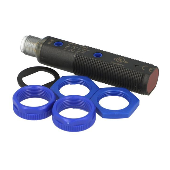
S5N-PA...W
Contrast sensor
INSTRUCTION MANUAL
Information on IO-Link communication is available on the last
page of this manual.
CONTROLS
OUTPUT LED
The yellow LED on indicates that the N.O. (normally open) output status
is closed.
READY LED
The green LED indicates a normal operating function.
If the green LED flashes, the acquisition has failed.
Please refer to the "SETTING" paragraph for setup procedure
indications.
SET PUSHBUTTON
A long pressure on the pushbutton activates the self-setting procedure.
INSTALLATION
S5N-PA...W: The sensor can be fixed by means of the M18x1 threaded
body through a 18 mm hole, using the specific washer and the
enclosed 24 mm nuts (maximum torque of tightening 1.5 Nm).
Alternatively, the sensor can be mounted through the two housing's
holes using two screws (M3x22 or longer) and nuts.
Amongst the various possible solutions, we suggest to choose the
combination that offers the best visibility of the signalling Leeds and the
easiest access to the SET pushbutton.
22 mm nuts, h=8 mm, (2 Nm maximum tightening torque) are available
to guarantee an improved torque.
The operating distance is measured from the front surface of the sensor
lens.
CONNECTIONS
The connections are compliant to the EN 60947-5-2 standard.
M12 CONNECTOR
TECHNICAL DATA
Power supply:
Ripple:
Current consumption
(output current excluded):
Outputs:
Output current:
Capacitive load:
Output saturation voltage:
Response time:
Switching frequency:
Jitter
Indicators:
Setting:
Operating mode:
Data retention:
Operating temperature:
Storage temperature:
Insulating strength:
Insulating resistance:
Operating distance (typical values):
Minimum spot dimension:
Emission type:
Ambient light rejection:
0.5 mm amplitude, 10 ... 55 Hz frequency, for every axis (EN60068-2-6)
Vibrations:
Shock resistance:
Housing:
Lenses:
Mechanical protection:
Connections:
Weight:
AtEx 2014/34/EU
Emission:
DIMENSIONS
10 ... 30 Vdc (limit values)
2 Vpp max.
25 mA max.
N.O. and N.C.; PNP or NPN; 30 Vcc max. (short-circuit protection)
100 mA max.
C
<= 1.5 uF @24V, I
= 100mA
max
load
C
<= 3.5 uF @24V, I
= 10mA
max
load
2 V max.
100 s
5 kHz
50 s
OUTPUT LED (YELLOW) / LED READY (GREEN)
SET pushbutton
LIGHT mode on N.O. output / DARK mode on N.C. output
non volatile EEPROM memory
-10 ... 55 °C
-20 ... 70 °C
500 Vac 1 min., between electronics and housing
>20 M 500 Vdc, between electronics and housing
10 mm 2 mm
4.5 mm
white light LED (400-700 nm)
according to EN 60947-5-2
11 ms (30 G) 6 shock for every axis (EN60068-2-27)
PBT
PMMA
IP67 Metal versions type 1 enclosure
M12 - 4 pole connector
25 g. max. connector vers.
I I 3G EX nA II T6 ;
I I 3D EX tD A22 IP67 T85°C
Exempt Risk Group (RG0) according to IEC 62471
SETTING
EASY TOUCH
The sensor uses the patent-covered EASY TOUCH technology that
allows a rapid and safe self-setting of the product.
Two different setting possibilities are available:
- EASY TOUCH
; a long pressure of the SET pushbutton allows self-
setting.
- FINE DETECTION; to be used only in particularly critical conditions,
this setting procedure is used only when the EASY TOUCH is not
sufficient.
Setting of S5N-PA...W
To achieve a correct sensor functioning, the coloured mark or object to
be detected has to be placed at the right reading distance.
- EASY TOUCH
(standard detection in the DARK mode)
The EASY TOUCH technology allows the functioning in the DARK
mode (mark presents a lower light intensity respect to the
background).
The mark to detect has to be placed correctly at the right reading
distance within the sensor spot.
Press the SET pushbutton until the READY LED turns OFF.
Release the SET pushbutton and wait for the READY LED to turn ON.
The sensor is now ready to detect the pre-set coloured mark or object
(output LED turns ON when the N.O. output is closed).
- Fine detection (DARK or LIGHT mode)
This mode offers an improved detection precision.
The sensor can function either in the DARK operating or in the LIGHT
operating mode (light-coloured mark on dark background).
The operating mode is selected automatically by the sensor.
The mark to detect has to be placed correctly at the right reading
distance within the sensor spot.
Press the SET button until the READY LED turns OFF.
Hold the SET button until the READY LED turns ON (3s).
The sensor is acquiring the mark.
When the READY LED flashes slowly, position the background to
coincide with the sensor spot and press the SET button again.
If the READY LED lights up permanently, the acquisition has been
successful; if the LED flashes quickly, the acquisition has failed due to
insufficient contrast. Pressing the SET button returns the sensor to the
previous setting. Repeat the procedure from the beginning.
The output LED is ON and the N.O. output is closed, when the sensor
is positioned on the pre-set coloured mark.
Datasensing S.r.l.
Strada S. Caterina 235 - 41122 Modena - Italy
Tel: +39 059 420411 - Fax: +39 059 253973 - www.datasensing.com
The warranty period for this product is 36 months. See General Terms and
Conditions of Sales for further details.
For information about the disposal of Waste Electrical and
Electronic Equipment (WEEE), please refer to the website at
www.datasensing.com.
© 2019-2022 Datasensing S.r.l ALL RIGHTS RESERVED. Without limiting
the rights under copyright, no part of this documentation may be reproduced,
stored in or introduced into a retrieval system, or transmitted in any form or by
any means, or for any purpose, without the express written permission of
Datasensing S.r.l. ♦ Datasensing and the Datasensing logo are trademarks of
Datasensing S.r.l. ♦ Datalogic and the Datalogic logo are registered trademarks
of Datalogic S.p.A. in many countries, including the U.S and the E.U.
806000100 Rev. A
Advertisement
Table of Contents

Related Manuals for Datalogic IO-Link S5N-PA W Series


Summary of Contents for Datalogic IO-Link S5N-PA W Series
- Page 1 Datasensing S.r.l. ♦ Datalogic and the Datalogic logo are registered trademarks Emission type: white light LED (400-700 nm) of Datalogic S.p.A. in many countries, including the U.S and the E.U. Ambient light rejection: according to EN 60947-5-2 0.5 mm amplitude, 10 … 55 Hz frequency, for every axis (EN60068-2-6) Vibrations: 806000100 Rev.
-
Page 2: Installation
übermittelt werden. ♦ Datasensing und das Logo von Datasensing sind Handelsmarken von LED weiß, 400 – 700 nm Datasensing S.r.l. ♦ Datalogic und das Logo von Datalogic sind eingetragene Handelsmarken von Sender, Wellenlänge: Datalogic S.p.A. in vielen Ländern, einschließlich den USA und der EU. -
Page 3: Manuel D'instructions
Datasensing S.r.l. ♦ Datasensing et le logo Datasensing sont des marques de Dimension du spot: 4.5 mm commerce de Datasensing S.r.l. ♦ Datalogic et le logo Datalogic sont des La distance opérationnelle est mesurée à partir de la surface frontale de Type d'émission: LED blanche 400 - 700 nm marques de commerce de Datalogic S.p.A. -
Page 4: Manuale Istruzioni
Datasensing S.r.l. ♦ Datasensing e il logo Datasensing sono marchi di Datasensing Tipo di emissione: led a luce bianca (400-700 nm) S.r.l. ♦ Datalogic e il logo Datalogic sono marchi registrati di Datalogic S.p.A. depositati Reiezione alla luce ambiente: come prescritto da EN 60947-5-2 La distanza operativa è... - Page 5 500 Vac 1 min.,电子设备与外壳之间 将其引入检索系统,不得以任何形式、通过任何方法对此文档进行传播,不得将此文档 绝缘电阻: >20 M 500 Vdc,电子设备与外壳之间 用于任何目的。♦ Datasensing 和 Datasensing 徽标是 Datasensing S.r.l. 的商标。 工作距离(典型值): ♦Datalogic 和 Datalogic 标志是 Datalogic S.p.A. 在美国和欧盟等诸多国家或地区的注册 10 mm 2 mm 商标。 最小光斑尺寸: 4.5 mm 发射类型: 白光 LED (400-700 nm) 环境光抑制:...
-
Page 6: Physical Layer
parameters PHYSICAL LAYER FEATURES Description Description Block Parameter IO-Link Revision Data Storage SIO Modus Min Cycle Time 5 ms (LED models) / 8 ms (Laser models) Parameter (write) access Supported Access Locks Data Storage Transmission Rate 38,4 kbit/s (COM2) PDInput: 24 Bit Process Data Length Device Profile: Smart Sensor PDOutput: 1 Bit... - Page 7 Lenght Value/Range Description Data Type Access* Remark (dec) Object Name (offset) 0x0010 (16) Vendor Name 9 octets DATALOGIC Informative StringT 0x0011 (17) Vendor Text 19 octets Empower your vision StringT 0x0012 (18) Product Name 15 octets Detailed product name StringT See “Device variant collection”...
- Page 8 Teach-in Parameters Index Parameter Subindex Lenght Value/Range Description Data Type Access* Remark (dec) Object Name (offset) 0x00 = SSC1 (default, C/Q pin and DO C/Q and DO outputs are antivalent. 0x003A (58) TI Select 1 octet Selection for Teach-in channel (volatile) UIntegerT pin) Teach SSC1 equals to teach SSC2...
- Page 9 Device Specific Parameters Index Parameter Subindex Lenght Value/Range Description Data Type Access* Remark (dec) Object Name (offset) 0 = no delay (default) 0x2 = Delay ON 1 octet 1(64) 0x3 = One Shot Select Delay mode (ON / OFF/ ONE SHOT) UIntegerT 0x4 = Delay OFF Delay [ms] *1000 / 141 (M03)
-
Page 10: Process Data
Events Event code (dec) Event name Event mode Event type Device status Remarks 0x4220 (16928) Temperature underrun Appears / Disappears Warning Out of specification only B01, C01, T01 0x4210 (16912) Temperature overrun Appears / Disappears Warning Out of specification 0x5100 (20736) General power supply fault Appears / Disappears Error... - Page 11 CE Compliance CE marking states the compliance of the product with essential requirements listed in the applicable European directive. Since the directives and applicable standards are subject to continuous updates, and since the manufacturer promptly adopts these updates, therefore the EU declaration of conformity is a living document. The EU declaration of conformity is available for competent authorities and customers through the manufacturer’s commercial reference contacts. Since April 20th, 2016 the main European directives applicable to the products require inclusion of an adequate analysis and assessment of the risk(s).
Need help?
Do you have a question about the IO-Link S5N-PA W Series and is the answer not in the manual?
Questions and answers