Table of Contents
Advertisement
Quick Links
EV-DMR18S
EV-DMR18SF
Door Station
User Manual
Please read this manual carefully before using the product you purchase, and keep it well for future use.
We reserve the right to modify the specification in this manual at any time without notice.
RF CARD
1
2
3
4
5
6
7
8
9
0
#
*
EV-DMR18S-DMR18SF-v01-04 20220131
Advertisement
Table of Contents

Related Manuals for Eyevision EV-DMR18S


Summary of Contents for Eyevision EV-DMR18S
- Page 1 User Manual RF CARD Please read this manual carefully before using the product you purchase, and keep it well for future use. We reserve the right to modify the specification in this manual at any time without notice. EV-DMR18S-DMR18SF-v01-04 20220131...
-
Page 2: Parts And Functions
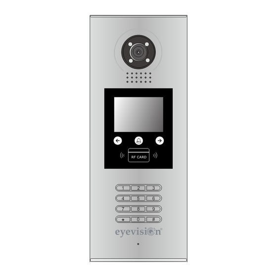
1.Parts and Functions Camera Lens Night View LED Adjustable Camera Speaker LCD Screen Touch Key Connectiong Port ID Card Window RF CARD Digital Keypad Microphone 128 mm With rainy cover 2. Terminal Descriptions SD Card Slot T/R - T/R+ CN-LK J/KMB JP-LK •... -
Page 3: Door Station Mounting
3.Door Station Mounting Surface mounting Camera angle The view for rainy Adjust the camera angle and attach the Drill holes in the wall to match the size of cover after mounted metal to the panel and wire correctly. screws and attach the rainy cover to the wall. Attach screws to fix the Attach the unit to the rainy The last view for all mounting... - Page 4 Flush mounting Camera angle Drill a hole and attach the The view for rainy Adjust the camera angle and attach the rainy cover to it cover after mounted metal to the panel and wire correctly. Attach screws to fix the Attach the unit to the rainy Attach the baffle to protect metal box...
-
Page 5: System Connection
4. System Connection Impedance Code=31 Code=30 OFF ON switch Code=29 Code=28 Code=3 Code=2 OFF ON Impedance switch Code=1 Code=0 PC7 / PC7H HDR-30-24 DPS(V2) RF CARD ID Code=0 NOTE:Here we take DT47M(the monitor) for example. -
Page 6: Door Lock Connections
5. Door Lock Connections 1. Internal Power Supply Mode Use the power of the system to supply for the electronic lock, so that the lock can be connected to the door station directly, without an additional power supply for the electronic lock. Note that the door station can only output 12Vdc power, therefore the kind of lock is limited. - Page 7 2. External Power Supply Mode When the electronic lock is over 12 Vdc, additional power supply for the lock is needed. • The power supply for the lock must be less than 48Vdc 1.5A. • The Jumper must be removed when using external power supply. The default setting is Power-on-to-Unlock type (Normally open mode) , if use Power-off-to-Unlock type,...
-
Page 8: Door Station Configurations
6. Door Station Configurations 1. About room code(address): Room Code(also called room address) is a code assigned to each monitor, to identify different monitors; each monitor have a unique room code in one buidling.The room Code is stored in each Monitor’s inner EEPROM memory, and does not lose even the monitor is power off. 2. - Page 9 Table 1: Item Submenu 1. ID Code 2. Unlock Timing [01] 3. Unlock Output 4. Monitor Timing [600] 1. Installer Setup 5. Doorplate Mode 6. Waiting Timing [040] 7. Talking Timing [090] 8. Installer Code ... 9. Default ... 1. Language 2.
- Page 10 Basic Tools Detail: Table 2(Installer Setup): Factory Item Description If only one door station is installed in this building, set to If multi door stations are installed, primary door station ID Code Single must be set to 0, and other slave door stations must be set from 1 to 3.
- Page 11 Table 3(Setup): Factory Item Description Language reserved. Tone Select Select the chime of Door Station in calling wait state. Adjust the tone volume for door station in calling. Range Tone Volume from 01~15 To change unlock code in Common Code Unlock mode, in Unlock Code 1111 4-digits format.
- Page 12 Table 4(Card Manage): Factory Item Description Add Card ... To add the user card Delete By Card To delete card by user card Delete By M.code To delete card by room code Cards Information To show the informations about cards Format To format informations about cards 4.
- Page 13 5. Change Unlcok Code: If door station runs as Debug State, you can press “1#” to activate Tools Menu, then select “2” to enter setup page,then select 4 item.If it runs as Normal State, follow these steps: 1 . L a n g u a g e [ 1 ] 4 .
- Page 14 6. User Card Management: This section explains how to configure the key fob function on DMR18S, The key fob is used to open the lock. Total 320 key fobs can be registered with one door station. When swiping the fob to the door station, the distance must be less than 3 centimeters. Key Fobs must be registered on the Door station that can be used to open the door.
- Page 15 Delete By Card: In Debug State , Press [1 #] --> [3] Card 2 . D e l e t e B y C a r d . . . 2 . D e l e t e B y C a r d . . . Manage -->[2] Delete By Card to enter Delete by Card page.as shown on the i Updated...
-
Page 16: Specification
7. Specification ● Power supply: DC24V ● Camera Lens : 1/4 ACS 4T image sensor with DSP processor ● Power consumption: Standby 94mA; Working status 157mA. ● Screen: 3.5 inch TFT ● Resolution: 320(R, G, B)X240 pixels ● Video signal: CCIR/EIA Optional ●...
Need help?
Do you have a question about the EV-DMR18S and is the answer not in the manual?
Questions and answers