Advertisement
Available languages
Available languages
Quick Links
Installation guide
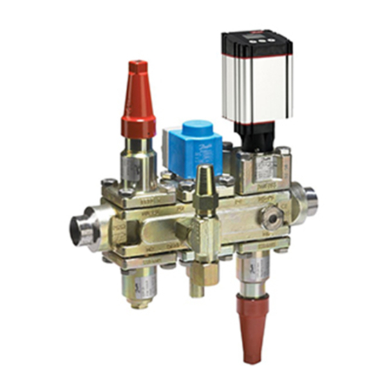
Valve Station
Types ICF 15, ICF 20, ICF 25, ICF SS 20 and ICF SS 25
Installation Installation Installation Instalación Instalação Montaż
ICF xx-2
1a
Welding Schweißen Soudure Soldadura Soldagem Spawanie
TIG/MIG/SMAW
2
Brazing | Löten | Brasage | Soldadura | Brasagem | Lutowanie twarde |
3
© Danfoss | Climate solutions | 2022.06
ICF xx-4
1b
安装
ICF xx-6
1c
焊接
Gas welding
Gasschweißen
Soudure au gaz
Soldadura con gas
Soldagem a gás
Spawanie gazowe
气焊
3
| 钎焊
5
6
3
089 0879
ICF xx-2 /ICF xx-4 /
ICF xx-6 + ICM/ICFD/ICFG
ICM
1
Ag40 Minimum 450–700 °C
Ag40 Minimum 450 – 700 °C
Minimum Ag40 450 – 700 °C
Ag40 mínimo 450 – 700 °C
Mínimo de Ag40 a 450 – 700 °C
Ag40, minimum 450 – 700 °C
Ag40,
450 – 700 °C
Ag40 最低 450 – 700 °C
AN13978644420802-001501 | 1
Advertisement

Subscribe to Our Youtube Channel
Related Manuals for Danfoss ICF 15


Summary of Contents for Danfoss ICF 15
- Page 1 Installation guide Valve Station Types ICF 15, ICF 20, ICF 25, ICF SS 20 and ICF SS 25 089 0879 安装 Installation Installation Installation Instalación Instalação Montaż ICF xx-2 ICF xx-4 ICF xx-6...
- Page 2 Maintenance Instandhaltung Maintenance Mantenimiento 维护 Manutenção Serwis ICF 15, ICF 20, ICF SS 20, ICF 25, ICF SS 25 PEEK: 12 mm 2 Nm (1.5 ft lb) O-ring O-ring ICFE ICFG 2 | AN13978644420802-001501...
- Page 3 80 Nm ICF SS 20-25 (58 ft lbs) ICF 15, ICF 20, ICF SS 20 Manual stem Handbetätigung Tige manuelle Vástago manual 手动阀杆 Operação manual Wrzeciono obsługi ręcznej Max. 20 Nm (15 ft lbs) at stop. Automatic mode (ICFE ON/OFF by coil) Max.
- Page 4 Connecteur de purge Dispositivo de protección de transporte Tapón de drenaje Dispositivo de segurança de transporte Plugue do dreno Zabezpieczenia transportowe Korek spustowy 排水塞 运输安全装置 40 Nm (29.5 ft lbs) 4 | AN13978644420802-001501 © Danfoss | Climate solutions | 2022.06...
- Page 5 TIG/MIG/SMAW welding ( g. Application the inside surfaces. 2) and auxiliary cooling is not needed at normal The ICF can be used in suction, liquid, hotgas heat impact. AN13978644420802-001501 | 5 © Danfoss | Climate solutions | 2022.06...
- Page 6 Maintenance ( g. 4) Operating the manual stem ( g. 6 to 8) Test with the system pressure higher ICF 15, ICF 20, ICF SS 20 ( g. 6a and 6b) than: - ICFS/ICFS SS - stop valve module ICFD 20 (Ammonia): 28 bar g /...
- Page 7 Module locations are indicated by M1, M2, M3, M4, M5 and M6. With respect to refrigerant ow, M1 is closest to inlet. location not possible *) ICF 15 - M1 and M2 modules are xed (stop valve and lter, respectively) Use only original Danfoss parts, including O-rings and gaskets for replacement.
- Page 8 Typ und der im Ventil Entfernen Sie vor dem Schweißen / Löten eingebauten Module. Flachdichtungen sind in der ICF 15 im alle Einsätze (Abb. 3 a/b). Modul M1/M2 und in der ICF 20-2/ICF 25/ Beim Löten ist eine zusätzliche Kühlung Installation (Abb.
-
Page 9: Montage
Handbetätigung (Abb. 6 bis 8) die am Ventil befestigte Ablassschraube mit die obere Mutter der Stopfbuchsbrille ICF 15, ICF 20, ICF SS 20 (Abb. 6a und 6b) Aluminiumdichtung (Pos. 2 in Abb. 10) ein erreicht, wenn Sie die Spindel des - ICFS/ICFS SS –... - Page 10 Moduleinbauorte werden durch M1, M2, M3, M4, M5 und M6 gekennzeichnet. In Bezug auf den Kältemittel uss ist M1 dem Eintritt am nächsten. Einbauort nicht möglich *) Die Module M1 und M2 der ICF 15 sind fest (Absperrventil bzw. Filter) Benutzen Sie für den Austausch nur Originalteile von Danfoss, einschließlich O-Ringe und Dichtungen.
-
Page 11: Entretien
Remplacez les joints plats et les joints Retirez le couvercle supérieur/l’insert nécessitent une orientation horizontale toriques altérés. Nettoyez les raccordements en de la vanne. utilisant un produit de nettoyage L'ICF est fournie avec tous les modules AN13978644420802-001501 | 11 © Danfoss | Climate solutions | 2022.06... - Page 12 3 h. Utilisation de la tige manuelle ( g. 6 à 8) atteignant l’écrou supérieur du presse- ICF 15, ICF 20, ICF SS 20 ( g. 6A et 6b) étoupe de la tige lorsque vous tournez Module de dégivrage ICFD - ICFS/ICFS SS : module vanne d’arrêt...
- Page 13 Les emplacements de modules sont indiqués par M1, M2, M3, M4, M5 et M6. En ce qui concerne le débit de uide frigorigène, M1 est le plus proche de l’entrée. L'emplacement n'est pas disponible *) ICF 15 : les modules M1 et M2 sont xes (vanne d'arrêt et ltre, respectivement) Utilisez exclusivement des pièces de rechange Danfoss d’origine, y compris pour les joints et joints toriques.
- Page 14 Refrigeración auxiliar necesaria para la soldadura Los módulos ICM, ICFD e ICFG requieren la ( g. 3b) para reducir el impacto térmico. instalación de la válvula en posición horizontal. 14 | AN13978644420802-001501 © Danfoss | Climate solutions | 2022.06...
-
Page 15: Montaje
52 bar g / 754 psi g es necesario preparar el módulo ICFD como se 8) ICF 15, ICF 20 e ICF SS 20 ( gs. 6a y 6b) muestra en la g. 11: - ICFS/ICFS SS (módulo de válvula de cierre) Desenrosque los 6 pernos de la brida y - ICFR/ICFR SS (válvula de regulación manual) - Page 16 Posición no válida. *) Estación de válvulas ICF 15: los módulos M1 y M2 son jos (válvula de cierre y ltro, respectivamente). Use exclusivamente piezas de repuesto originales de Danfoss, incluidas las juntas tóricas y las juntas planas para sustitución.
- Page 17 As gaxetas planas estão presentes no a g. 1. A ICF deve ser instalada com a seta módulo M1/M2 da ICF 15 e em todos os no sentido do uxo. Siga estas etapas durante a brasagem módulos da ICF20-2/ICF 25/ICF SS 25.
- Page 18 Operação manual ( g. 6 a 8) vedação ao girar a haste manual no Remova o dispositivo de segurança de ICF 15, ICF 20, ICF SS 20 ( g. 6A e 6b) sentido horário para abrir a válvula. transporte (pos. 1 na g. 10).
- Page 19 As localizações dos módulos são indicadas por M1, M2, M3, M4, M5 e M6. Em relação ao uxo de refrigerante, M1 é o mais próximo da entrada. localização impossível *) ICF 15 - módulos M1 e M2 são xos (válvula de bloqueio e ltro, respectivamente) Utilize somente peças originais da Danfoss, incluindo O-rings e juntas para as substituições.
- Page 20 Przed spawaniem / lutowaniem twardym nie są uszkodzone.Jeśli uszczelki i Zawór w modułach ICM, ICFD i ICFG musi należy wyjąć wszystkie wkłady (rys. 3 a/b). pierścienie o-ring są naruszone, wymienić je. być umieszczony poziomo. 20 | AN13978644420802-001501 © Danfoss | Climate solutions | 2022.06...
- Page 21 Zabezpieczenie na czas transportu 6 do 8) ICF 15, ICF 20, ICF SS 20 (rys. 6a i 6b) należy go uszczelnić, wykręcając wrzeciono z Usunąć zabezpieczenia transportowe (poz. 1 na - ICFS/ICFS SS — moduł zaworu odcinającego momentem siły 8 Nm (5,9 funta/stopę).
- Page 22 Gniazda modułów oznaczono symbolami M1, M2, M3, M4, M5 i M6. M1 znajduje się najbliżej wlotu czynnika chłodniczego. umiejscowienie niemożliwe *) Typ modułów roboczych w gniazdach M1 i M2 w zaworze ICF 15 jest ustalone (są to odpowiednio: zawór odcinający i ltr) Należy stosować wyłącznie oryginalnych części zamienne rmy Danfoss, w tym pierścienie o-ring i uszczelki.
- Page 23 ICF 25 / ICF SS 25. ICF. . 3 a/b). . 4A, 4B) ICF 15: 1 . 3b) M3/M4 2 ICM. . 1) ICF 20-4/6 ICF SS 20-4/6: . 1. . 3b): ICM, ICFD ICFG AN13978644420802-001501 | 23 © Danfoss | Climate solutions | 2022.06...
- Page 24 ICFD . 5, 6 7) . 10). . 5). . 10) . 6-8) ICF 15, ICF 20, ICF SS 20 ( . 6a 6b) 8 · (5,9 - ICFS/ICFS SS – - ICFR/ICFR SS – - ICFN/ICFN SS – ICFD 20 ( .)/406...
- Page 25 ICF 25) ICFE 20H/ICFE SS 20H ICF 25) ICFO/ICFO SS ICF 25) ICFW/ICFW SS ICFD ICFG M1, M2, M3, M4, M5 M6. * ) ICF 15 – M1 M2 Danfoss, Danfoss. AN13978644420802-001501 | 25 © Danfoss | Climate solutions | 2022.06...
- Page 26 块,并关闭可手动操作的 M l1 和 M l4/ - 对 于 ICM 20 电动阀的模块,需检查 Ml6,以便在系统准备运行前对阀门内部 ICM, ICFD 和 ICFG 模块需要放置于水 PEEK 基座是否受损或是有擦伤。若受 实施保护。 平位置。 损或是有擦伤,需更换 PEEK 基座。 如果不是立即装配阀门,则需在内表面涂 上一些防锈油。 ICF 交付时已装配完毕全部功能模块。模 块可取出进行检修,并可在安装时相对 于阀体呈 90° 角朝四个方向旋转。请确 保 ICFD 周围有足够的空间以便于进行安 装。 带阀杆的 ICF 可用于手动开启电磁阀。 26 | AN13978644420802-001501 © Danfoss | Climate solutions | 2022.06...
- Page 27 的数值(见图 5)。 一起拧下并拆下 注 意 - 杠件的浮动端不得旋松,不 要使用浮子进行旋松 操作手动阀杆 (图 6 至图 8) 4. 重 新装好浮球阀体并用图 10 所示 ICF 15, ICF 20, ICF SS 20(图 6a 和 的扭矩拧紧 6 个法兰螺栓 6b) 5. 在 系统压力高于下列压力的情况下 - ICFS/ICFS SS – 截止阀模块 进行测试: - I CFR/ICFR SS – 手动调节阀模块...
- Page 28 电动阀模块 ICFB/ICFB SS 封口顶盖 ICFA/ICFA SS 电子膨胀阀模块(不可用于 ICF 25) ICFE 20H/ICFE SS 电磁阀模块(不可于ICF 25) ICFO/ICFO SS 手动开启模块(不可用于ICF 25) ICFW/ICFW SS 焊接模块 ICFD 除霜模块 ICFG 导阀驱动的伺服模块 模块位置显示为 Ml1、Ml2、Ml3、Ml4、Ml5 和 Ml6。由于制冷剂流动,Ml1 距离进口最近。 不可用的位置 * 已固定 ICF 15 - Ml1 和 Ml2 模块(分别为止回阀和过滤器) 只可使用丹佛斯原厂元件,包括用于更换的 O 型圈和垫片。 新部件的材料应经证明适合相关制冷剂。 如有疑问,请与丹佛斯联系。 28 | AN13978644420802-001501 © Danfoss | Climate solutions | 2022.06...
Need help?
Do you have a question about the ICF 15 and is the answer not in the manual?
Questions and answers