Advertisement
Available languages
Available languages
Quick Links
Installation guide
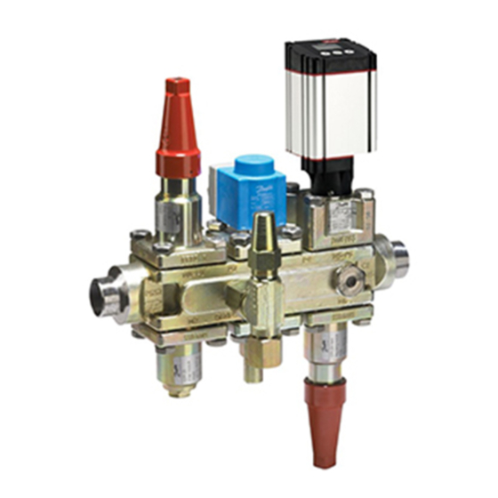
Valve Station
Types ICF 15, ICF 20, ICF 25, ICF SS 20 and ICF SS 25
Installation Installation Installation Instalación Instalação Montaż Монтаж 安装
ICF xx-4
1a
Welding Schweißen Soudure Soldadura Soldagem Spawanie Сварка 焊接
TIG/MIG/SMAW
2
© Danfoss | DCS (MWA) | 2017.11
ICF xx-6
1b
ICF xx-4 / ICF xx-6 + ICM/ICFD
1c
Gas welding
Gasschweißen
Soudure au gaz
Soldadura con gas
Soldagem a gás
Spawanie gazowe
Газовая сварка
气焊
3
DKRCI.PI.FT0.C9.ML | 520H5450 | 1
ICM
Advertisement

Subscribe to Our Youtube Channel
Related Manuals for Danfoss ICF 15


Summary of Contents for Danfoss ICF 15
- Page 1 Installation guide Valve Station Types ICF 15, ICF 20, ICF 25, ICF SS 20 and ICF SS 25 Installation Installation Installation Instalación Instalação Montaż Монтаж 安装 ICF xx-4 ICF xx-6 ICF xx-4 / ICF xx-6 + ICM/ICFD Welding ...
- Page 2 Maintenance Instandhaltung Maintenance Mantenimiento Manutenção Serwis Техническое обслуживание 维护 ICF 15, ICF 20, ICF SS 20, ICF 25, ICF SS 25 ICM (all sizes): O-ring ICM (alle Größen): O-ring ICM (toutes les tailles) :...
- Page 3 ICF SS 20-25 (58 ft lbs) ICF 15, ICF 20, ICF SS 20 Manual stem Handbetätigung Tige manuelle Vástago manual Operação manual Wrzeciono obsługi ręcznej Ручное управление 手动阀杆 Max. 25 Nm (18 ft lbs) (Closing ICFR: max. 4 Nm (3 ft lbs) Max.
- Page 4 Tighten at site. An der Stelle festziehen. Resserrer sur site. Aplicar torque en el sitio. Apertar em campo. Dokręcić po montażu. 40 Nm (29.5 ft lbs) Закрутите. 现场锁紧 4 | DKRCI.PI.FT0.C9.ML | 520H5450 © Danfoss | DCS (MWA) | 2017.11...
- Page 5 ICFD module a test pressure of the system until the system is ready for operation. Flat gaskets are present in ICF 15 module must not exceed 28 bar (406 psi g), unless All other valve modules are able, in any the ICFD float is temporarily taken out for M1/M2 and ICF 25/ICF SS 25 all modules.
- Page 6 (pos. 2 in fig 10) and tighten with the torque indicated. (fig. 6 to 8) ICF 15, ICF 20, ICF SS 20 (fig. 6a and 6b) Test pressure maximum 28 bar (406 psi g) - ICFS/ICFS SS - stop valve module...
- Page 7 Module locations are indicated by M1, M2, M3, M4, M5 and M6. With respect to refrigerant flow, M1 is closest to inlet. location not possible *) ICF 15 - M1 and M2 modules are fixed (stop valve and filter, respectively) Use only original Danfoss parts, including O-rings and gaskets for replacement.
- Page 8 Entfernen Sie vor dem Schweißen (Abb. 3) alle vorhanden: (siehe Abb. 4a, 4b) Der Regelbereich ist abhängig vom Funktionsmodule. Bei einer normalen ICF 15: Ein Gummidichtung im Modul M3 ausgewählten Typ und der im Ventil Wärmeeinwirkung ist keine zusätzliche eingebauten Module.
-
Page 9: Montage
Handbetätigung (Abb. 6 bis 8) Transportschutz Entfernen Sie nach dem Transport den ICF 15, ICF 20, ICF SS 20 (Abb. 6a und 6b) Sicherungsstift (Pos. 1 in Abb. 10). Setzen Sie - ICFS/ICFS SS – Absperrventilmodul die am Ventil befestigte Ablassschraube mit - ICFR/ICFR SS –... - Page 10 Einbauort nicht möglich *) Die Module M1 und M2 der ICF 15 sind fest (Absperrventil bzw. Filter) Benutzen Sie für den Austausch nur Originalteile von Danfoss, einschließlich O-Ringe und Dichtungen. Die Werkstoffe der neuen Komponenten sind für das entsprechende Kältemittel zertifiziert.
-
Page 11: Entretien
(voir fig. 4a, 4b) Retirez tous les inserts avant le soudage selon les modules fonctionnels installés ICF 15 : 1 Joint en caoutchouc dans (fig. 3). Un refroidissement auxiliaire est dans l’ICF. chaque module M3/M4 et 2 joints inutile en cas de choc thermique normal. - Page 12 Pour forcer l’ouverture de l’électrovanne au moyen de la tige manuelle, tournez celle-ci à fond vers le haut, dans le sens inverse des aiguilles d’une montre. (Mode manuel) 12 | DKRCI.PI.FT0.C9.ML | 520H5450 © Danfoss | DCS (MWA) | 2017.11...
- Page 13 *) ICF 15 : les modules M1 et M2 sont fixes (vanne d'arrêt et filtre, respectivement) Utilisez exclusivement des pièces de rechange Danfoss d’origine, y compris pour les joints et joints toriques. Les matériaux des nouvelles pièces sont homologués pour le fluide frigorigène utilisé.
- Page 14 4b): especial atención. ICF 15: 1 Junta de goma en cada módulo M3/ Rango de regulación Soldadura con gas M4 y 2 juntas tóricas en el módulo ICM. El rango de regulación depende del tipo elegido Desmonte todos los módulos antes de efectuar...
- Page 15 (ref. 2, fig. 10) y apriételos aplicando el par de manual (figs. 6 a 8) apriete indicado. ICF 15, ICF 20 e ICF SS 20 (figs. 6a y 6b) Presión de prueba máxima: 28 bar g - ICFS/ICFS SS (módulo de válvula de cierre) - ICFR/ICFR SS (válvula de regulación manual)
- Page 16 Posición no válida. *) Estación de válvulas ICF 15: los módulos M1 y M2 son fijos (válvula de cierre y filtro, respectivamente). Use exclusivamente piezas de repuesto originales de Danfoss, incluidas las juntas tóricas y las juntas planas para sustitución.
- Page 17 As juntas planas estão presentes no Após a soldagem, recomenda-se fechar se a o módulo ICFD for temporariamente módulo M1/M2 da ICF 15 e em todos os estas válvulas novamente para evitar retirado para permitir o teste, conforme módulos da ICF SS 25.
- Page 18 3 horas. Operação manual (fig. 6 a 8) ICF 15, ICF 20, ICF SS 20 (fig. 6A e 6b) - ICFS/ICFS SS - módulo válvula de Módulo de degelo ICFD bloqueio Proteção de transporte...
- Page 19 As localizações dos módulos são indicadas por M1, M2, M3, M4, M5 e M6. Em relação ao fluxo de refrigerante, M1 é o mais próximo da entrada. localização impossível *) ICF 15 - módulos M1 e M2 são fixos (válvula de bloqueio e filtro, respectivamente) Utilize somente peças originais da Danfoss, incluindo O-rings e juntas para as substituições.
- Page 20 Uszczelki są zamontowane w modułach M1 Po zakończeniu spawania zaleca się ponowne Zawór blokowy ICF może być stosowany i M2 zaworu ICF 15 oraz we wszystkich zamknięcie tych zaworów, aby nie dopuścić do w rurociągach ssawnych par suchych lub możliwości przepływu gazów, i utrzymywanie modułach zaworów ICF 25 i ICF SS 25.
- Page 21 (rys. od 6 do 8) odszraniania Zabezpieczenie na czas transportu ICF 15, ICF 20, ICF SS 20 (rys. 6a i 6b) Usunąć zabezpieczenia transportowe (poz. 1 na - ICFS/ICFS SS — moduł zaworu odcinającego rys. 10). W zaworze zamontować korek spustowy - ICFR/ICFR SS —...
- Page 22 Gniazda modułów oznaczono symbolami M1, M2, M3, M4, M5 i M6. M1 znajduje się najbliżej wlotu czynnika chłodniczego. umiejscowienie niemożliwe *) Typ modułów roboczych w gniazdach M1 i M2 w zaworze ICF 15 jest ustalone (są to odpowiednio: zawór odcinający i filtr) Należy stosować wyłącznie oryginalnych części zamienne firmy Danfoss, w tym pierścienie o-ring i uszczelki.
- Page 23 Плоские прокладки имеются в модуле M1/ Клапанная станция ICF может использоваться тефлоновые сёдла при сварке. M2 клапанной станции ICF 15 и во всех во всасывающих линиях, жидкостных линиях, модулях клапанных станций ICF 25/ICF SS 25. линиях горячего газа и линиях жидкости/ После...
- Page 24 Снимите устройство защиты на время Ручное управление (рис. 6-8) транспортировки (поз. 1 на рис. 10). ICF 15, ICF 20, ICF SS 20 (рис. 6a и 6b) Установите сливную заглушку и алюминиевую - ICFS/ICFS SS – модуль запорного клапана прокладку, входящие в комплект поставки...
- Page 25 Местоположения модулей обозначены как M1, M2, M3, M4, M5 и M6. По отношению к потоку хладагента M1 является ближайшим к входу модулем. Размещение невозможно * ) ICF 15 – модули M1 и M2 являются неподвижными (запорный клапан и фильтр соответственно) Для замены используйте только подлинные детали производства компании Danfoss, включая уплотнительные кольца и прокладки.
- Page 26 进 行焊接(图 2)或气焊方式(图 3) 在安装阀门之前,阀门进口和出口必须采 用保护盖防止阀组件内部生锈。 TIG/MlIG/SMlAW 焊接在 TIG/MlIG/SMlAW 焊 接前(图 2)无需拆卸任何功能模块,在正常 受热的情况下无需采用辅助制冷。 必须采取预防措施尽量避免出现焊渣。 为第一个模块上(Ml1)配备截止阀并在最后 一个模块(Ml4 或 Ml6)上配备截止阀、节流 阀或截止阀/止回阀的 ICF 阀组件,建议轻 轻打开这些阀门(从关闭位置拧开约 1 圈), 从而使焊接热量对 TEFlon 座的影响降至最 低。 26 | DKRCI.PI.FT0.C9.ML | 520H5450 © Danfoss | DCS (MWA) | 2017.11...
- Page 27 起重新安装,请勿使用浮子进行紧 操作手动阀杆(图 6 至图 8) 固。 7. 重新装好浮球阀体并用图 10 所示的 ICF 15, ICF 20, ICF SS 20(图 6a 和 6b) 扭矩拧紧 6 个法兰螺栓 - I CFS/ICFS SS – 截止阀模块 建议在这样的重复拆装之后用新的垫片替 - I CFR/ICFR SS – 手动调节阀模块 换受压的原有浮球阀体垫片。 - I CFN/ICFN SS – 截止阀/止回阀模块...
- Page 28 ICFO/ICFO SS 手动开启模块(不可用于ICF 25) ICFW/ICFW SS 焊接模块 ICFD 除霜模块 模块位置显示为 Ml1、Ml2、Ml3、Ml4、Ml5 和 Ml6。由于制冷剂流动,Ml1 距离进口最近。 不可用的位置 *已固定 ICF 15 - Ml1 和 Ml2 模块(分别为止回阀和过滤器) 只可使用丹佛斯原厂元件,包括用于更换的 O 型圈和垫片。 新部件的材料应经证明适合相关制冷剂。 如有疑问,请与丹佛斯联系。 28 | DKRCI.PI.FT0.C9.ML | 520H5450 © Danfoss | DCS (MWA) | 2017.11...
Need help?
Do you have a question about the ICF 15 and is the answer not in the manual?
Questions and answers