Table of Contents
Advertisement
© Copyright 2018
EVERTZ MICROSYSTEMS LTD.
5292 John Lucas Drive
Burlington, Ontario
Canada L7L 5Z9
Phone:
+1 905-335-3700
Sales:
sales@evertz.com
Tech Support: service@evertz.com
Web Page:
http://www.evertz.com
Version 1.0, Apr 2018
The material contained in this manual consists of information that is the property of Evertz Microsystems and is intended solely for the use of
purchasers of the 5700ACO. Evertz Microsystems expressly prohibits the use of this manual for any purpose other than the operation of the
5700ACO.
All rights reserved. No part of this publication may be reproduced without the express written permission of Evertz Microsystems Ltd. Copies
of this manual can be ordered from your Evertz dealer or from Evertz Microsystems.
5700ACO
Automatic Changeover
User Manual
Fax: +1 905-335-3573
Fax: +1 905-335-7571
Twitter:
@EvertzTV
Advertisement
Table of Contents

Subscribe to Our Youtube Channel
Related Manuals for evertz 5700ACO


Summary of Contents for evertz 5700ACO
- Page 1 Version 1.0, Apr 2018 The material contained in this manual consists of information that is the property of Evertz Microsystems and is intended solely for the use of purchasers of the 5700ACO. Evertz Microsystems expressly prohibits the use of this manual for any purpose other than the operation of the 5700ACO.
- Page 2 This page left intentionally blank...
- Page 3 IMPORTANT SAFETY INSTRUCTIONS The lightning flash with arrowhead symbol within an equilateral triangle is intended to alert the user to the presence of uninsulated “Dangerous voltage” within the product’s enclosure that may be of sufficient magnitude to constitute a risk of electric shock to persons. The exclamation point within an equilateral triangle is intended to alert the user to the presence of important operating and maintenance (Servicing) instructions in the literature accompanying the product.
- Page 4 WARNING Changes or modifications not expressly approved by Evertz Microsystems Ltd. could void the user’s authority to operate the equipment. Use of unshielded plugs or cables may cause radiation interference. Properly shielded interface cables...
- Page 5 Evertz products are for informational use only and are not warranties of future performance, either expressed or implied. The only warranty offered by Evertz in relation to this product is the Evertz standard limited warranty, stated in the sales contract or order confirmation form.
- Page 6 5700ACO Automatic Changeover This page left intentionally blank Revision 1.0...
-
Page 7: Table Of Contents
5700ACO Automatic Changeover TABLE OF CONTENTS OVERVIEW ........................... 1 1.1. HOW TO USE THIS MANUAL ..................... 5 INSTALLATION ..........................7 2.1. REAR PANEL........................7 2.1.1. Coaxial Connections ....................7 2.1.2. Balanced AES, DARS and Analog Audio Connections* ..........8 2.1.3. Linear Time Code and GPIO Connections* ............... 8 2.1.4. - Page 8 5.2. General Control ......................... 38 5.3. General Status ........................39 5.4. Voting Control ........................40 5.5. GPO Status ........................42 5.6. 5700ACO Fault Trap Controls ..................43 5.6.1. Analog Faults ......................43 5.6.2. AES DARS Faults* ....................44 Page ii...
- Page 9 Figure 2-4 : GPO1 Output Circuitry ......................... 15 Figure 2-5 : GPO2 Output Circuitry ......................... 15 Figure 3-1 : Model 5700ACO Front Panel ....................... 17 Figure 3-2 : Front Panel & Card Edge Control ....................19 Figure 4-1 : 5700ACO Switching Logic ......................27 Figure 5-1 : VistaLINK –...
- Page 10 5700ACO Automatic Changeover This page left intentionally blank Page iv Revision 1.0...
-
Page 11: Overview
For example if a level, pulse width, phase, time code error or other abnormality is detected, the 5700ACO circuitry will trigger and the entire bank of signals will be switched to the backup 5700MSC-IP. In manual mode the changeover can be operated from a GPI or from the front panel switch. - Page 12 Hot swappable redundant power supply standard • VistaLINK capable offering remote monitoring and configuration capabilities via SNMP using the ® model 9000NCP Network Control Panel or Evertz VistaLINK PRO or other third party SNMP ® manager software. Signal Type Inputs...
-
Page 13: Figure 1-1 : 5700Aco Block Diagram
ANALOG AUDIO (2) LTC Slicer, GPI LTC/IRIG (2), GPI (2) Inputs LTC Slicer, GPI Latching GPO from processor (2), Relays GPI from Inputs(2) LTC/IRIG (2) Out LTC/IRIG VistaLINK Interface (RS232) Figure 1-1 : 5700ACO Block Diagram Page 3 Revision 1.0... -
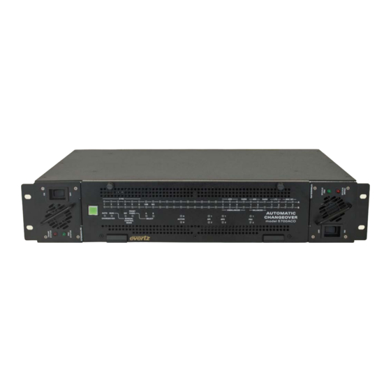
Page 14: Figure 1-2 : 5700Aco Front View
5700ACO Automatic Changeover Figure 1-2 : 5700ACO Front View Figure 1-3 : 5700ACO Rear View Page 4 Revision 1.0... -
Page 15: How To Use This Manual
HOW TO USE THIS MANUAL This manual is organized into 5 chapters: Overview, Installation, Operation, Technical Information, and VistaLINK Configuration and Control. The overview section provides a brief summary of the 5700ACO ® module as well as features. Chapter 2 provides a detailed description of rear panel connectors, and how the module should be connected. - Page 16 5700ACO Automatic Changeover This page left intentionally blank Page 6 Revision 1.0...
-
Page 17: Installation
2.5 give more detail on connecting the system. 2.1.1. Coaxial Connections There are 16 groups of 3 BNC connectors on the 5700ACO rear panel. In each group there is one labelled A, and another labelled B for connection of the indicated signal from the respective 5700MSC-IP Master Clock/SPG. -
Page 18: Balanced Aes, Dars And Analog Audio Connections
5700ACO Automatic Changeover 2.1.2. Balanced AES, DARS and Analog Audio Connections* DARS/AES/ANALOG: These 16 pin terminal strips are for connecting the balanced version of the AES and DARS signals as well as two balanced analog audio signals. The output cables can be secured into the removable portion of the terminal strips using a small screwdriver. -
Page 19: Ethernet Connections
The 5700ACO can be configured using the VistaLINK -C Configuration tool connected by Ethernet. ® (See section 5.1 for information on configuring the IP address of the 5700ACO and section 5.1.1 for information about installing and using the VistaLINK software) ®... -
Page 20: Power Connections
2.2. MOUNTING The 5700ACO is equipped with rack mounting angles and fits into a standard 19 inch by 1 3/4 inch (483 mm x 45 mm) rack space. The mounting angles may be removed if rack mounting is not desired. -
Page 21: 5700Msc-Ip Connections
2.4. 5700MSC-IP CONNECTIONS The 5700MSC-IP unit connected to the A inputs of the 5700ACO will be called Master A. The 5700MSC-IP unit connected to the B inputs of the 5700ACO will be called Master B. 5700M SC-10G LTC REF IN... -
Page 22: Sync Outputs
2.4.2. 10 MHz Output* Connect the 10 MHz output of the Master A 5700MSC-IP unit to the A 10 MHz input of the 5700ACO. Connect the 10 MHz output of the Master B 5700MSC-IP unit to the B 10 MHz input of the 5700ACO. -
Page 23: Balanced Dars, Aes1, Aes2 And Analog Audio Outputs
2.4.7. LTC and GPIO Connections Connect the AUX I/O output of the Master A 5700MSC-IP unit to the A AUX I/O input of the 5700ACO using one of the straight through interconnect cables provided. Connect the AUX I/O output of the Master B 5700MSC-IP unit to the B AUX I/O input of the 5700ACO using one of the straight through interconnect cables provided. -
Page 24: Connecting The General Purpose Inputs And Outputs
Auto-changeover, as well as the GPI inputs and outputs from the two 5700MSC-IP units. The signals on the top row of the connector are for the 5700ACO only and do not connect to the 5700MSC-IP units. (See section 3.3) The signals on the bottom row of the connector are connected directly to the 5700MSC-IP units (see section 2.4.5). -
Page 25: Figure 2-4 : Gpo1 Output Circuitry
5700ACO Automatic Changeover 10 K GPO Pin from internal circuit Figure 2-4 : GPO1 Output Circuitry + 5 VDC 10 K ohm from internal GPO Pin circuit 10 ohm Figure 2-5 : GPO2 Output Circuitry * Requires factory installed +AUX hardware option on 5700MSC-IP, IP Master Clocks are available at extra cost. - Page 26 5700ACO Automatic Changeover This page left intentionally blank Page 16 Revision 1.0...
-
Page 27: How To Operate The Automatic Changeover
70 LED status indicators. Figure 3-1 : Model 5700ACO Front Panel 3.1. AN OVERVIEW OF THE STATUS INDICATORS There are 70 status indicators located on the front panel that show operational status of the 5700ACO at a glance. 3.1.1. Operating Mode Indicators AUTO This green LED will be “On”... -
Page 28: Input Indicators
Master B device are present and valid. If the LED is excluded from the voting pool, the LED will be dim. The 5700ACO determines that an input is present and valid according to the following criteria: Sync: H timing detect for 5700ACO... -
Page 29: Automatic Changeover Mode
CTL SEL (Manual Control Mode) switch to the GPI position. The Manual and GPI LEDs will come on. The 5700ACO will decide whether to select the A or B inputs based on the ACO GPI inputs on the top row of the terminal strip on the rear panel. There are two GPI changeover modes described in sections 3.3.1. -
Page 30: Manual Switch Changeover Mode
CTL SEL mode switch to the FP (Front Panel) position. The Manual and Front Panel LEDs will come on. The 5700ACO will decide whether to select the A or B inputs based on the position of the CHG SELECT switch. When the CHG SELECT switch is set to A Master A will be selected and the A LED will come On. -
Page 31: Gpi Input Mode
Table 3-3 : Single GPI Mode Operation In single GPI mode the 5700ACO is controlled by the ACO GPI1 input on the top row of the terminal strip on the rear panel. GPI2 is not used in this mode. When GPI1 is low Master A will be selected. -
Page 32: Changeover Rate
Table 3-7 : Change Limiting Switch Settings When DIP switch 8 and DIP switch 7 are in the Off position, the 5700ACO may change an unlimited number of times depending on inputs when in automatic mode. When DIP switch 7 is in the On Page 22 Revision 1.0... -
Page 33: Gpo Tally Outputs
The default condition of the 5700ACO outputs when there is no power applied is that the Master that was last active will be selected, and will be indicated by the GPO1 relay. GPO2 will be high impedance. - Page 34 5700ACO Automatic Changeover This page left intentionally blank Page 24 Revision 1.0...
-
Page 35: Technical Description
5700ACO Automatic Changeover TECHNICAL DESCRIPTION 4.1. AUTO CHANGEOVER SWITCH CRITERIA Understanding how the ACO makes its changeover switch decisions is vital to designing, monitoring, and troubleshooting a synchronizing signal distribution system. This section provides information on how the ACO determines when it is time to switch to the other input. -
Page 36: One Change Mode
5700ACO Automatic Changeover There are three automatic modes of operation: 1. One Change Mode: Switch one time only on the first valid switch criteria. 2. Dual Change Mode: Suspend all switching when two consecutive criteria are met within a short time period. -
Page 37: Unlimited Change Mode
Switch to B Switch Figure 4-1 : 5700ACO Switching Logic 4.4. SPECIFICATIONS 4.4.1. LTC Outputs Standard SMPTE 12M frame rate set by 5700MSC-IP Number of outputs Connector 3 pin male XLR type outputs... -
Page 38: Coaxial Inputs And Outputs
GPI2 Low: Selects Master B Outputs GPO1 Low: Master A is selected (default when the 5700ACO has no power) High: Master B is selected GPO2 Low: Master A & Master B differ or PSU failure High: Master A and B have equivalent signals Page 28 Revision 1.0... -
Page 39: Msc General Purpose Inputs And Outputs
Ethernet 10 Base-T IEEE 802.3 standard for 10 Mbps baseband CSMA/CD local area network The 5700ACO is designed to be used with either 10Base-T (10 Mbps), 100Base-TX (100 Mbps) also known as Fast Ethernet or 1000Base-T (1000 Mbps) also known as Gigabit Ethernet, twisted pair Ethernet cabling systems. -
Page 40: Electrical
UPGRADING THE FIRMWARE 4.5.1. Overview The firmware in the 5700ACO is contained on a FLASH EPROM. From time to time firmware updates will be provided to add additional features to the unit. The following equipments are needed in order to update the Firmware: •... -
Page 41: Terminal Program Setup
“UPLOAD FILE NOW, CONTROL-X TO CANCEL” For example: EVERTZ MCF5272 MONITOR 2.3 BUILD 3 (66 MHZ) COPYRIGHT 1997, 1998, 1999, 2000, 2001, 2002 EVERTZ MICROSYSTEMS LTD. 28F160C3B FLASH DETECTED BRD=5700ACO MODEL=BA5700ACO PROD=5700ACO... -
Page 42: Uploading The New Firmware
The COM serial port is used to configure the 5700ACO and read back status. Connect a straight through serial cable (supplied with the 5700ACO) between the COM serial port on the rear panel and a PC’s serial port. Start TeraTerm (or an equivalent terminal program) on the PC... - Page 43 Once the unit is powered-up, the TeraTerm connection displays boot-up status information and once completed, ends with the “Status Message” as shown below: Initialization Completed – 5700ACO Running Press the <Enter> key to see the main Menu. In the Main Menu, the following options are present for module configuration.
-
Page 44: Network Configuration
(5) Use DHCP (6) Enable Ethernet (S) Save and exit (X) Exit without saving 4.6.2. SNMP Configuration 2) SNMP Configuration – set the TRAP destination IP address which originate at this 5700ACO (if enabled) --------------------------------------------------- Trap Destination 1: 192.168.1.88 ---------------------------------------------------... -
Page 45: Voting Control
5700ACO Automatic Changeover 4.6.3. Voting Control 3) Voting Control – set which input channel pair is included in the voting pool. ---- 5700 ACO Voting Control ---- (1) Sync 1 (2) Sync 2 (3) Sync 3 (4) Sync 4 (5) Sync 5... -
Page 46: Show Status
5700ACO Automatic Changeover 4.6.4. Show Status (4) Show Status – shows a synopsis of all of the above 3 items, and also shows the status of all input channels. There are no settable controls under this menu item. Software V1.0 34... -
Page 47: Vistalink Configuration And Control
5.1.1. Installing V LINK ISTA ® In order to control the 5700ACO, you will need at least version 10.5.4 or later of the VistaLINK ® configuration tool. If you received the VistaLINK Toolkit CD-ROM with the 5700ACO, insert it into the ®... -
Page 48: Using Vistalink To Configure The 5700Aco
(because it is on another subnet) it can be manually added by right clicking the Hardware node and selecting Add/Update frame. Right click the discovered 5700ACO to open the Configuration View screen. The screen is broken into ten tabs. To view the other screens, click on the appropriate tab of the configuration screen. -
Page 49: General Status
DIP switches 7 and 8 (See section 3.3.4). Current Output: Displays which bank is selected as the current output of the 5700ACO. Bank Preference: This field reports which bank is preferred by 5700ACO. The bank preference is set by the bank priority DIP switches (See section 3.3.3). -
Page 50: Voting Control
5700ACO Automatic Changeover 5.4. VOTING CONTROL The Voting Control section is used to configure how the 5700ACO makes decisions regarding valid signals. It also decides when to switch to the backup signals. Figure 5-3 : VistaLINK – Voting Control ®... - Page 51 5700ACO Automatic Changeover General 10Mhz voting: If this field is set to include, the 10Mhz input status will be included in the voting process. If set to exclude, the input will not be included in the process. Word Clock Voting: If this field is set to include, the word clock input status will be included in the voting process.
-
Page 52: Gpo Status
GPO STATUS The GPO Status section enables the user to view the status of various GPO Input and Output conditions for the 5700ACO. These status conditions will not be updated live unless the auto refresh is enabled. Figure 5-4 : VistaLINK –... -
Page 53: 5700Aco Fault Trap Controls
5700ACO Automatic Changeover 5.6. 5700ACO FAULT TRAP CONTROLS Figure 5-5 to Figure 5-9 5-9 show the 5 tabs used to determine which SNMP trap messages will be sent by the 5700ACO. 5.6.1. Analog Faults The Analog Faults section, as illustrated in Figure 5-5, allows the user to enable or disable Analog traps and view trap status. -
Page 54: Aes Dars Faults
5700ACO Automatic Changeover 5.6.2. AES DARS Faults* As illustrated in Figure 5-6, this section allows the user to enable AES DARS traps and monitor the trap status. Figure 5-6 : VistaLINK – AES DARS Faults ® To enable a particular trap, simply click the box located beside each trap so that a check-mark appears. -
Page 55: Ltc Faults
5700ACO Automatic Changeover 5.6.3. LTC Faults The LTC Faults section, as illustrated in Figure 5-7, allows the user to enable LTC traps and monitor the trap status. Figure 5-7 : VistaLINK – LTC Faults ® To enable a particular trap, simply click the box located beside each trap so that a check-mark appears. -
Page 56: Figure 5-9 : Vistalink - Faults
5700ACO Automatic Changeover To enable a particular trap, simply click the box located beside each trap so that a check-mark appears. When a check-mark is present, the SNMP trap is enabled. When a check-mark is not present, the trap is disabled.
Need help?
Do you have a question about the 5700ACO and is the answer not in the manual?
Questions and answers