Table of Contents
Advertisement
Quick Links
© Copyright 1994, 2006
EVERTZ MICROSYSTEMS LTD.
5288 John Lucas Drive, Burlington, Ontario, Canada, L7L 5Z9
Phone:
905-335-3700
Internet: Tech Support:
Sales:
Web Page:
Revision 2.0 March 2006
The material contained in this manual consists of information that is the property of Evertz Microsystems and is
intended solely for the use of purchasers of the model 5950 Time code Reader. Evertz Microsystems expressly
prohibits the use of this manual for any purpose other than the operation of the 5950.
All rights reserved. No part of this publication may be reproduced without the express written permission of
Evertz Microsystems Ltd. Copies of this guide can be ordered from your Evertz products dealer or from Evertz
Microsystems.
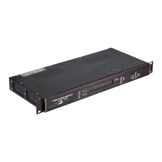
Model 5950
LTC / VITC Timecode Reader
Character Inserter
Instruction Manual
Fax:
905-335-3573
eng@evertz.com
sales@evertz.com
http://www.evertz.com
Advertisement
Table of Contents

Subscribe to Our Youtube Channel
Related Manuals for evertz 5950


Summary of Contents for evertz 5950
- Page 1 Revision 2.0 March 2006 The material contained in this manual consists of information that is the property of Evertz Microsystems and is intended solely for the use of purchasers of the model 5950 Time code Reader. Evertz Microsystems expressly prohibits the use of this manual for any purpose other than the operation of the 5950.
- Page 2 WARNING Changes or Modifications not expressly approved by Evertz Microsystems Ltd. could void the user’s authority to operate the equipment. Use of unshielded plugs or cables may cause radiation interference. Properly shielded interface...
- Page 3 Evertz products are for informational use only and are not warranties of future performance, either express or implied. The only warranty offered by Evertz in relation to this product is the Evertz standard limited warranty, stated in the sales contract or order confirmation form.
- Page 4 Model 5950 Time Code Reader Manual This page left intentionally blank Revision 2.0...
-
Page 5: Table Of Contents
Model 5950 Time Code Reader Manual TABLE OF CONTENTS INTRODUCTION ......................... 1-1 1.1. HOW TO USE THIS MANUAL ....................1-2 INSTALLATION........................... 2-1 2.1. REAR PANEL CONNECTIONS ....................2-1 2.1.1. Linear Time Code Connections..................2-1 2.1.2. Video Connections ......................2-1 2.1.3. - Page 6 Upgrading The Firmware ....................4-5 Figures Figure 2-1: Rear Panel Layout – Rev 1 versions of 5950 ............2-1 Figure 2-2: Rear Panel Layout – Rev 2 versions of 5950 ............2-1 Figure 2-3: Dubbing and Off-line Character Burn In ..............2-7 Figure 2-4: VITC Translation to LTC for Editing................
- Page 7 Model 5950 Time Code Reader Manual INTRODUCTION ........................1-1 1.1. HOW TO USE THIS MANUAL ....................1-2 Revision 2.0...
- Page 8 Model 5950 Time Code Reader Manual This page left intentionally blank Revision 2.0...
-
Page 9: Introduction
The model 5950 contains two separate readers that can be operated independent of each other, or can be linked to form an auto LTC/VITC reader. The model 5950 can be configured in one of three basic operating modes: •... -
Page 10: How To Use This Manual
5950 to be conveniently configured for particular customer requirements. There are two different versions of the 5950 hardware. Rev 1 versions have the rear panel layout shown in Figure 2-1 and rev 2 versions have the rear panel layout shown in Figure 2-2. - Page 11 SAMPLE CONFIGURATIONS ....................2-6 Figures Figure 2-1: Rear Panel Layout – Rev 1 versions of 5950 ............2-1 Figure 2-2: Rear Panel Layout – Rev 2 versions of 5950 ............2-1 Figure 2-3: Dubbing and Off-line Character Burn In ..............2-6 Figure 2-4: VITC Translation to LTC for Editing................
- Page 12 Model 5950 Time Code Reader Manual This page left intentionally blank Revision 2.0...
-
Page 13: Installation
5950. Figure 2.1 above shows the rear panel connectors provided on the model 5950. Sections 2.1.1 to 2.1.5 describe the specific signals that should be connected to the 5950. Figure 2-3 and Figure 2-4 give sample connection diagrams for connecting the model 5950. -
Page 14: Parallel Remote Control Connections
2.1.4. Serial Port Connections - Rev 2 versions only SERIAL: Rev 2 versions of the 5950 are fitted with a 9 pin subminiature 'D' connector labeled SERIAL. This port is used to update the firmware in the 5950 and is configured at the factory for a ‘straight through RS-232 connection to a PC... -
Page 15: Power Connections
Model 5950 Time Code Reader Manual 2.1.5. Power Connections LINE: Rev 1 versions of the 5950 may be set for either 115v/60 Hz or 230v/50 Hz AC operation. The voltage selector switch is accessible on the rear panel. The line voltage connector contains an integral slow blow fuse (and a spare one). -
Page 16: Power Requirements - Rev 2 Versions
Power requirements for Rev 2 versions are 100 to 240 volts AC at 50 or 60 Hz. The later 5950 units have a universal power supply that automatically senses the input voltage. Power should be applied by connecting a 3-wire grounding type power supply cord to each of the power entry modules on the rear panel. -
Page 17: Reader Video Input
Model 5950 Time Code Reader Manual 2.4. READER VIDEO INPUT Video associated with the LTC code or video with VITC recorded on it is connected to the READER VITC IN loop. The video input has a high impedance input tapped off the loop through, therefore the input must be terminated with 75 ohms at the end of the line. -
Page 18: Sample Configurations
LTC is properly timed to the video. The source video must be connected to the READER VITC IN loop of the model 5950 to ensure correct timing of the output LTC to the video. PLAYBACK VTR... -
Page 19: Figure 2-4: Vitc Translation To Ltc For Editing
EDITOR Figure 2-4: VITC Translation to LTC for Editing The recovered VITC is translated to LTC by the model 5950, which can be read by the LTC reader in the edit controller. The new LTC is generated at approximately play speed so that the edit controller can read it during slow motion decision making and also for cueing and parking the VTR during editing. - Page 20 5010-VITC must be used in the place of the model 5950 on the record VTR. During the edit pre-roll, when the record VTR is in playback, the jam-sync generator will follow the numbers read from the record machine.
- Page 21 Model 5950 Time Code Reader Manual OPERATING INSTRUCTIONS....................3-1 3.1. FRONT PANEL OVERVIEW ....................... 3-1 3.1.1. Overview of the Pushbuttons ................... 3-1 3.1.2. Status Indicators ......................3-2 3.2. FRONT PANEL DISPLAY FUNCTIONS ..................3-3 3.2.1. Special Front Panel Indicators ..................3-3 3.3.
- Page 22 Model 5950 Time Code Reader Manual This page left intentionally blank Revision 2.0...
-
Page 23: Operating Instructions
3.1. FRONT PANEL OVERVIEW The model 5950 Time Code Reader provides a display of time or user bit information from its reader using a 16 digit (12 digit on Rev 1 versions) alphanumeric display on the front panel, or using characters keyed into the input video. -
Page 24: Status Indicators
Model 5950 Time Code Reader Manual CHAR GEN MODE Initiates VCG window select mode and highlights the selected window. Use the arrow keys to move the window, use the CHAR GEN ON/OFF key to turn the window on or off. -
Page 25: Front Panel Display Functions
Model 5950 Time Code Reader Manual 3.2. FRONT PANEL DISPLAY FUNCTIONS The TIME/UB key is used to select which data is being displayed in the alphanumeric display. Press the TIME/UB to change from displaying time or user bits from the reader. On Rev 1 versions the left character of the front panel display indicates whether time or user bits is being displayed. -
Page 26: Positioning The Overall Character Display
VCG FIELDS item in the VCG menu. 3.4. ON SCREEN PROGRAMMING MENU - OVERVIEW The key to the operational flexibility of the model 5950 lies in the powerful on screen programming menu system which uses the built in character generator. -
Page 27: Figure 3-2: On Screen Programming Menu Overview
Model 5950 Time Code Reader Manual READER CONFIGURATION ASSIGNMENT CHAR SIZE VIDEO TYPE TINY AUTO VITC SMALL NTSC LTC/VITC LARGE MODE CHAR STYLE HORZ CHAR SIZE TIME USERBITS WHITE HORIZONTAL TIME DATA WHITE ON BLACK CHAR SIZE = 10 TIME... -
Page 28: Programming The Reader Setup Functions
Model 5950 Time Code Reader Manual The two vertical arrow keys ( , ) allow you to move vertically within the drop down menus. When you have selected the desired menu item, press the SELECT key to reveal the sub menu choices for that item. Use the two vertical arrow keys ( , ) to move vertically within the sub menu. -
Page 29: Figure 3-4: Reader Drop Down Menu
Figure 3-4: READER Drop Down Menu The ASSIGNMENT menu is used to select how the reader hardware is ASSIGNMENT configured. The model 5950 can be configured in three different ways. VITC LTC/VITC Select LTC to configure the reader for Linear Time Code (LTC) reading only. - Page 30 Model 5950 Time Code Reader Manual When the VITC LINES sub menu is first selected, the START line number will be in reverse video indicating it can be changed. Press the up and down ( , ) keys to change the starting line. Press the right ( ) key to highlight the END line, indicating that it can be changed.
-
Page 31: Programming The Character Generator Functions
Model 5950 Time Code Reader Manual 3.6. PROGRAMMING THE CHARACTER GENERATOR FUNCTIONS The VCG drop down menu is used to select various characteristics of the VCG display. Figure 3-5 shows the items on the VCG drop down menu. The following descriptions appear in the order they appear on the menu. -
Page 32: Programming The Overall Configuration Functions
Model 5950 Time Code Reader Manual Select WHITE ON BLACK to key white characters on a black background mask into the picture. Select BLACK to disable the background and key black characters directly into the picture. Select BLACK ON WHITE to key black characters on a white background mask into the picture. -
Page 33: Figure 3-6: Configuration Drop Down Menu
VITC LINE RANGE menu setting. Make sure that you re-check this setting NTSC when you change the video standard. Select AUTO if you want to have the 5950 auto detect PAL and NTSC video. Select NTSC if you are using NTSC video. -
Page 34: Parallel Remote Control Functions
35, which is approximately 1 volt peak to peak. TO ADJUST The FACTORY RESET menu item Is used to reset the 5950 to the factory FACTORY RESET default parameters. Press the TIME/UB + SELECT keys when the sub menu screen is displayed to reset the 5950 to factory defaults. - Page 35 Model 5950 Time Code Reader Manual VCG ENABLE Provides an alternate method of turning the character inserter generator On and Off. The character inserter is turned On by a high to low transition on this input, and turned Off by a low to high transition.
- Page 36 Model 5950 Time Code Reader Manual This page left intentionally blank OPERATING INSTRUCTIONS Revision 2.0 Page 3-14...
- Page 37 Model 5950 Time Code Reader Manual TECHNICAL DESCRIPTION ....................4-1 4.1. OVERVIEW ..........................4-1 4.2. SPECIFICATIONS........................4-2 4.2.1. LTC Reader ........................4-2 4.2.2. LTC Translator ......................... 4-2 4.2.3. VITC Reader ........................4-2 4.2.4. Character Generator ......................4-2 4.2.5. Parallel Remote Control....................4-2 4.2.6.
- Page 38 Model 5950 Time Code Reader Manual This page left intentionally blank Revision 2.0...
-
Page 39: Technical Description
1,2,3,4,1, etc. (1,2,3,4,5,6,7,8,1, etc. for PAL). The character inserter is also used for the on Screen Programming menus which are used to set up the various operational modes of the model 5950. TECHNICAL DESCRIPTION Revision 2.0... -
Page 40: Specifications
Model 5950 Time Code Reader Manual 4.2. SPECIFICATIONS 4.2.1. LTC Reader Standard SMPTE 12M, 25, 30 Fps Drop & Non Drop Frame Connector XLR Type 3 pin female connector Signal Level 0.2 to 4V p-p, balanced or unbalanced Speed 1/30th to 70x play speed, forward and reverse, machine dependent 4.2.2. -
Page 41: Electrical
4.3. DIP SWITCH FUNCTIONS The main circuit board of the 5950 contains an 8 position DIP switch which is used to invoke various diagnostic and calibrations functions. On The 5200 main circuit card the DIP switch is closed when it is pressed down on the right side. -
Page 42: Calibrating The Character Generator
4.5. UPDATING TO A NEW FIRMWARE VERSION Rev 1 versions of the 5950 have an EPROM program memory device that must be replaced in order to upgrade the firmware. Contact the Customer Serivce department at the factory for further information. -
Page 43: Upgrading The Firmware
WinZip utility (available from our FTP site) To set up the 5950 for programming at 38400 baud hold down the SETUP key while you apply power to the 5950. When the 5950 completes its boot-up sequence, the front panel will display LOAD FLASH - 38400. - Page 44 When the Flash PROM is erased, the Flash loader will start to send the new firmware to the 5950. The Flash loader will give a status report as it sends each line of the HEX file to the 5950. During programming the 5950 front panel display will show LOADING - XXXXX.
Need help?
Do you have a question about the 5950 and is the answer not in the manual?
Questions and answers