Table of Contents
Advertisement
Quick Links
© Copyright 2008
EVERTZ MICROSYSTEMS LTD.
5288 John Lucas Drive,
Burlington, Ontario,
Canada L7L 5Z9
Phone:
905-335-3700
Sales:
sales@evertz.com
Tech Support: service@evertz.com
Web Page:
http://www.evertz.com
Version 1.0, June 2008
The material contained in this manual consists of information that is the property of Evertz Microsystems and is
intended solely for the use of purchasers of the VIP-X. Evertz Microsystems expressly prohibits the use of this
manual for any purpose other than the operation of the VIP-X. Due to on going research and development, features
and specifications in this manual are subject to change without notice.
All rights reserved. No part of this publication may be reproduced without the express written permission of Evertz
Microsystems Ltd. Copies of this manual can be ordered from your Evertz dealer or from Evertz Microsystems
VIP-X SYSTEM MANUAL
Fax: 905-335-3573
Fax: 905-335-7571
Advertisement
Table of Contents

Subscribe to Our Youtube Channel
Related Manuals for evertz VIP-X


Summary of Contents for evertz VIP-X
- Page 1 VIP-X. Evertz Microsystems expressly prohibits the use of this manual for any purpose other than the operation of the VIP-X. Due to on going research and development, features and specifications in this manual are subject to change without notice.
- Page 2 This page left intentionally blank...
- Page 3 IMPORTANT SAFETY INSTRUCTIONS The lightning flash with arrowhead symbol within an equilateral triangle is intended to alert the user to the presence of un-insulated, dangerous voltage within the product’s enclosure that may be of sufficient magnitude to constitute a risk of electric shock to persons. The exclamation point within an equilateral triangle is intended to alert the user to the presence of important operating and maintenance (i.e.: servicing) instructions in the literature accompanying the product.
- Page 4 WARNING Changes or modifications not expressly approved by Evertz Microsystems Ltd. could void the user’s authority to operate the equipment. Use of unshielded plugs or cables may cause radiation interference. Properly shielded interface cables with the shield connected to the chassis ground of the device must be used.
-
Page 5: Table Of Contents
3.2.4. Installing the 7767VIPX-RP2 Rear Plate in the 7700FR-D frame ......20 3.2.5. Installing the XLINK cable ..................21 SYSTEM COMMUNICATION ......................23 4.1. NETWORK CONNECTIVITY ....................23 4.1.1. Xenon Based VIP-X Solution..................23 4.1.2. EQX Based VIP-X Solution ..................24 7767VIPX8X2, 7767VIPX16X2 MODULES ...................25 VIP-X - i Revision 1.0... - Page 6 VIP-X System Manual 5.1. VIDEO INPUTS AND OUTPUTS..................25 5.2. GENLOCK REFERENCE ..................... 26 5.3. DVI VIDEO CONNECTIONS ....................26 5.4. GENERAL PURPOSE INPUTS AND OUTPUTS..............27 5.5. LTC AND SERIAL DATA INPUTS (AUXILIARY INTERFACE)........... 29 5.6. ETHERNET NETWORK CONNECTIONS................31 5.7.
- Page 7 VIP-X System Manual MODULE CONFIGURATION ......................43 9.1. CONFIGURING THE MODULE VIA THE CARD EDGE MENU...........43 9.1.1. Configuring the Display .....................44 9.2. CONFIGURING THE MODULE USING THE MODULE SERIAL PORT......45 9.2.1. Network Configuration ....................46 9.2.2. On Board Server Setup .....................47 9.2.3. SNMP Configuration....................48 9.2.4.
- Page 8 VIP-X System Manual SYSTEM MANAGER SOFTWARE ....................73 12.1. INSTALLING SOFTWARE ....................73 12.2. CONFIGURING A SYSTEM ....................73 CONFIGURING THE 3000 DCP DESKTOP CONTROL PANEL ..........75 13.1. FOR PC – DCP SETUP ......................75 REMOTE MONITORING/CONTROL............... 77 VISTALINK ®...
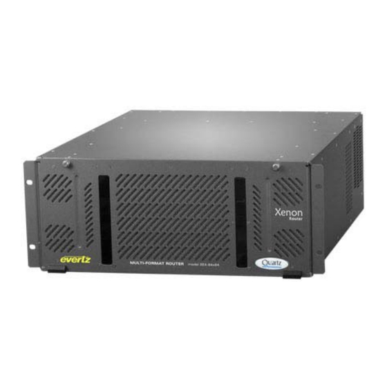
- Page 9 VIP-X System Manual Figures Figure 1-1: VIPX64, VIPX128, VIPX288 & MVP/Maestro Control Software ............ 1 Figure 1-2: Flow of Output ..........................2 Figure 1-3: X-LINK Interconnect ........................3 Figure 2-1: Xenon 4RU – 64x64 Router ......................5 Figure 2-2: Xenon 8RU – 128x128 Video Router..................... 5 Figure 2-3: EQX 16RU –...
- Page 10 VIP-X System Manual Figure 12-1: Unlocking the Server ......................... 74 Figure 12-2: System Connection Status Window ................... 74 Tables Table 1-1: X-LINK Enable Router Outputs ....................... 3 Table 5-1: Supported Resolutions at 50Hz and 60Hz ..................26 Table 5-2: HD-15 Pin-Out ..........................30 Table 5-3: Standard RJ45 Wiring Colour Codes ....................
- Page 11 Evertz products are for informational use only and are not warranties of future performance, either expressed or implied. The only warranty offered by Evertz in relation to this product is the Evertz standard limited warranty, stated in the sales contract or order confirmation form.
- Page 12 VIP-X System Manual This page left intentionally blank VIP-X - viii Revision 1.0...
-
Page 13: Overview
Building the next control room will be simple using the VIP-X, as it enables two complex items in the control room to function as a single system. The VIP-X eliminates system complexity, saves space and is more economical compared to the traditional autonomous solutions. -
Page 14: X-Link Enabled Routers
1.1. X-LINK ENABLED ROUTERS X-LINK outputs are an additional set of outputs from Evertz standard router platforms. They are for the purpose of providing connectivity to monitoring devices. X-LINK outputs do not limit the number of outputs on the router, X-LINK outputs are in addition to the standard video router outputs. Please refer to the Table 1-1 below for more details. -
Page 15: X-Link Interconnect
VIP-X System Manual STANDARD VIDEO TOTAL ROUTER PRODUCT INPUTS X-LINK OUTPUTS OUTPUTS OUTPUTS 64 3G/HD/SD Xenon 4RU (3*X-LINK) Xenon 8RU 128 3G/HD/SD (6*X-LINK) EQX 16RU (9*X-LINK) 576+ EQX 26RU 32 Mon outs (8*X-LINK) Table 1-1: X-LINK Enable Router Outputs 1.2. - Page 16 VIP-X System Manual This page left intentionally blank VIP-X - 4 Revision 1.0...
-
Page 17: Hardware Details
2.1.1. Xenon 4RU The Xenon 4RU router can be used as a VIP-X foundation platform, with up to 64 3G/HD/SD inputs and up to 64 outputs for signal routing. One of the two output boards in the Xenon 4RU can be “X-LINK”... -
Page 18: Eqx 16Ru
VIP-X System Manual 2.1.3. EQX 16RU The EQX 16RU router can be used as a VIP-X foundation platform, no other router is more advanced in terms of technology and redundancy. EQX 16RU offers up to 288 3G/HD/SD inputs and 288 outputs for signal routing. -
Page 19: Eqx 26Ru
VIP-X System Manual 2.1.4. EQX 26RU The EQX 26RU router can be used as a VIP-X foundation platform, offering the largest possible footprint for both router and multi-image displays. EQX 26RU offers up to 576 3G/HD/SD inputs and 576 outputs for signal routing. The EQX26 is “X-LINK” enabled via the addition of the EQX-OP36- XLINK output module and two EQX16-288x288 cross point modules installed in the primary and redundant cross point locations for the frame. -
Page 20: Vip-X Components
VIP-X System Manual 2.2. VIP-X COMPONENTS 2.2.1. XE-OP32SX-XLINK Xenon output module with 32 SD-SDI outputs via mini-BNC (DIN) outputs plus three (3) X-LINK outputs (see Appendix A for information on DIN connectors). A single XE-OP32SX-XLINK output card can be installed in the Xenon 4RU router, and two XE-OP32SX-XLINK output cards can be installed in the Xenon 8RU router. -
Page 21: Eqx-Op288-Xlink
VIP-X System Manual 2.2.3. EQX-OP288-XLINK EQX-OP288-XLINK EQX passive rear output module provides up to nine (9) X-LINK outputs. The output board is installed in the rear of EQX 16RU router frame below the power connector and above the redundant frame controller rear module. -
Page 22: Eqx-Op36-Xlink
VIP-X System Manual 2.2.5. EQX-OP36-XLINK EQX-OP36-XLINK output module is used to provide X-LINK outputs from the EQX routers both 16RU and 26RU by providing X-LINK from a router output slot, as compared to the EQX-OP288-XLINK module that provides X-LINK outputs without using all of the output slots in the router. The EQX-OP36- XLINK provides a single X-LINK output plus 4 BNC outputs. -
Page 23: X-Link Cable
VIP-X System Manual 2.2.6. X-LINK Cable The X-LINK cable provides a high-density extension of the additional outputs from the routers to the 7767VIPX-RP2 rear module and the 3000MVP-RP4-XLINK. The standard X-LINK cable length provided with all X-LINK enabled products is 5 meters (15 feet). -
Page 24: Xlink-Bhp2U-96C
Evertz does not recommend the use of this BHP to feed downstream equipment expecting SMPTE standard video signals. Evertz makes no claims that the coax copy of X-LINK video will meet the SMPTE standards for SD, HD or 3Gbps. The BHP panel can be used to extend X-LINK by converting to standard coax cable (Belden 1694A or comparable cable) and offering extension up to 50m (150 feet). -
Page 25: 3000Mvp-Rp4-Xlink
The rear panel for the 3000FR is to enable support for X-LINK connections from “X-LINK” enabled router platforms. It supports up to four (4) 3000 series input modules in the VIP-X, and occupies 4 slots in the 3000FR. Up to 4 3000MVP-OV-SNX cards, or 3000MVP-OV-HSN or a mix of the two can be used with this rear plate. -
Page 26: 7767Vipx-Rp2
VIP-X System Manual 2.2.9. 7767VIPX-RP2 The rear panel for the 7767VIPX display modules supports up to two 7767VIPX16x2 modules, or up to two 7767VIPX8x2 modules. The 7767VIPX-RP2 occupies 5 slots in the 7700FR-D frame. It provides connectivity from the router to the 7767VIPX display module inputs via the X-LINK connector. There are two X-LINK connectors on the rear plate, which allows for separate sources of X-LINK to connect to the 7767VIPX module. -
Page 27: 7700Fr-D Frame
VIP-X System Manual The following is an example of how X-LINK connections are distributed to the 7767VIPX16x2 cards that are plugged into the 7767VIPX-RP2 rear plate: 7767VIPX16x2 7767VIPX X-LINK - RP2 7767VIPX16x2 Figure 2-15: Distribution of X-LINK connections to the 7767VIPX16x2... -
Page 28: 7700Fr-Dq Frame
VIP-X System Manual 2.2.11. 7700FR-DQ FRAME The 7700FR-DQ frame provides up to 360W per power supply. The frame utilizes side venting for improved air-flow through the frame, resulting in the use of lower air-flow fans which perform with a quieter operation. The 7700FR-DQ frame is recommended to be used in installs where noise is of concern. -
Page 29: Hardware Installation
VIP-X System Manual HARDWARE INSTALLATION This section provides installation instructions for the various VIP-X hardware components. It offers recommendations as to placement and positioning of the hardware noted above. 3.1. RACKING VIP-X FRAMES 3.1.1. Xenon 4RU and 8RU The Xenon frames both 4RU and 8RU are to be mounted in a standard 19” rack. The total depth of the Xenon frame is 17.75”, and therefore a rack depth of at least 30”... -
Page 30: Figure 3-1: Xenon 4Ru With One Xe-Op32Hx-Xlink Output Card Installed
VIP-X System Manual Figure 3-1: Xenon 4RU with One XE-OP32HX-XLINK Output Card Installed Figure 3-2: Xenon 8RU with Two XE-OP32HX-XLINK Output Cards Installed VIP-X - 18 Revision 1.0... -
Page 31: Installing Eqx-Op288-Xlink And Eqx-Op576-Xlink Rear Module In Eqx 16Ru
VIP-X System Manual 3.2.2. Installing EQX-OP288-XLINK and EQX-OP576-XLINK Rear Module in EQX 16RU The EQX-OP288-XLINK and EQX-OP576-XLINK are installed in the EQX 16RU router. The EQX 16RU frame must be factory X-LINK enabled; the frame type must be EQX16FR-XLINK or part of an EQX package with –XLINK option. The EQX-OP288- XLINK and EQX-OP576-XLINK output modules will not work in any of the non-XLINK enabled EQX 16RU frames. -
Page 32: Installing The 7767Vipx-Rp2 Rear Plate In The 7700Fr-D Frame
VIP-X System Manual Both primary and redundant cross points must be installed in the router to enable the outputs for the EQX-OP36-XLINK output card. No cross point redundancy is available when using this output card. The output slot in the opposite half of the router cannot be an EQX-OP36-XLINK or EQX-OP36-MON card. -
Page 33: Installing The Xlink Cable
VIP-X System Manual 3.2.5. Installing the XLINK cable The X-LINK cable XLINK-BHP-5 or XLINK-BHPS-5 should be installed last after all cabling is completed in the rack. The X-LINK cable is keyed so that it can only be installed in a single direction. - Page 34 VIP-X System Manual This page left intentionally blank VIP-X - 22 Revision 1.0...
-
Page 35: System Communication
Use the computer’s appropriate Ethernet port for this connectivity. All Ethernet based control panels must be on the same network as the VIP-X system in order to control the system. All control panels, and software clients connect via TCP/IP to the System Manager software, which relays the information to the hardware as appropriate. -
Page 36: Eqx Based Vip-X Solution
Use the computer’s appropriate Ethernet port for this connectivity. All Ethernet based control panels must be on the same network as the VIP-X system in order to control the system. All control panels, and software clients connect via TCP/IP to the System Manager software, which relays the information to the hardware as appropriate. -
Page 37: 67Vipx8X2, 7767Vipx16X2 Modules
SD-SDI, or 10-bit serial digital video signals compatible with the SMPTE 424M, SMPTE 292M and SMPTE 259M-C standards. Since the 7767VIPX-RP2 rear panel accommodates two VIP-X modules, the rear plate has two X-LINK connectors (one for each VIP-X module). VIP-X - 25... -
Page 38: Genlock Reference
Since the 7767VIPX-RP2 rear panel accommodates two VIP-X modules, the rear plate two has DVI-D connections for each VIP-X module. DVI-D 1A and 2A for the first VIP- X module and DVI-D 1B and 2B for the second VIP-X module. -
Page 39: General Purpose Inputs And Outputs
VIP-X System Manual 5.4. GENERAL PURPOSE INPUTS AND OUTPUTS GPI interfacing with the 7767VIPX is possible through 4 general purpose inputs (pins 10, 11, 12, 13) and 2 general purpose outputs (pins 4, 9) available on the HD-15 connector on the rear plate of the module. -
Page 40: Figure 5-4: Interfacing Gpis To A High Voltage Gpi System
VIP-X System Manual 24V = working voltage Example: Control Device 24VDC (working voltage) 1N4148 Diode VIP GND GPI of VIP note: the control device VIP GND and the VIP GNDs must be tied together AXICOM 1M06 Relay (24V = working voltage) -
Page 41: Ltc And Serial Data Inputs (Auxiliary Interface)
The 7767VIPX has an LTC input and a serial data port available on the HD-15 connector on the module’s rear plate. Please refer to Table 5-2 for more information on the HD-15 connector. Since the 7767VIPX-RP2 rear panel accommodates two VIP-X modules, the rear plate has a total of two HD-15 connectors (one for each VIP-X module). -
Page 42: Figure 5-6: 7767Vipx16X2/8X2 Hd-15 General Purpose Pin-Out
VIP-X System Manual Table 5-2 below, identifies the pin assignments for the general-purpose HD-15 connector mounted on the rear plate for the VIPX X-LINK enabled Advanced Duo modules. FUNCTION DESCRIPTION RS-422: RX+ Used for RS-422 communication – VIP RX+, to be connected to... -
Page 43: Ethernet Network Connections
Since the 7767VIPX-RP2 rear panel accommodates two VIP-X modules, the rear plate has Ethernet ports 1A and 2A for the first VIP-X module and 1B and 2B for the second VIP-X module. -
Page 44: Table 5-3: Standard Rj45 Wiring Colour Codes
VIP-X System Manual The straight-through RJ-45 cable can be purchased or can be constructed using the pinout information in Table 5-3. A colour code wiring information is provided in Table 5-3 for the current RJ-45 standards (AT&T 258A or EIA/TIA 258B colour coding shown). Also refer to the notes following the table for additional wiring guide information. - Page 45 VIP-X System Manual Devices on the Ethernet network continually monitor the receive data path for activity as a means of checking that the link is working correctly. When the network is idle, the devices also send a link test signal to one another to verify link integrity. The rear panel is fitted with two LEDs to monitor the Ethernet connection.
-
Page 46: 7767Vipx8X2/16X2 Block Diagram
VIP-X System Manual 5.7. 7767VIPX8X2/16X2 BLOCK DIAGRAM GLINK Coax In (background) DVI-D 1 (digital only) Background Mode Graphic DVI-D 2 (digital only) Replicated Outputs Video Output Formatter HD-SDI/SD-SDI 1 HD-SDI/SD-SDI 2 GLINK Coax Out 8/16 SD-SDI/ HD-SDI/ Video A/D 3Gbps... -
Page 47: Technical Description
XGA (1024x768) to WUXGA (1920x1200). 7767VIPX modules are installed in Evertz 7700FR-D frame, which uses high output power supplies. Up to 4 modules or two pairs of 7767VIPX8x2 cards can be installed in a single 7700FR-D frame. -
Page 48: Serial Video Output
VIP-X System Manual 6.1.4. Serial Video Output Standard: Selectable HD/SD serial monitoring output (720p, 1080i, 625i, 525i) Number of Outputs: 2 Connector: BNC per IEC 60169-8 Amendment 2 Signal Level: 800mV nominal DC Offset: 0V ±0.5V Rise and Fall Time: 200ps nominal (HD), 740ps nominal (SD) Overshoot: <... -
Page 49: 7767Vipx16X2 Specifications
Resolutions range from XGA (1024x768) to WUXGA (1920x1200). 7767VIPX modules are installed in Evertz 7700FR-D frame, which uses high output power supplies. Up to 4 modules or two pairs of 7767VIPX16x2 cards can be installed in a single 7700FR-D frame. -
Page 50: Genlock Input
VIP-X System Manual 6.2.5. Genlock Input Type: NTSC/PAL colour black Level: 1V p-p nominal Connector: BNC via 7700FR-D (frame genlock) 6.2.6. General Purpose Interface I/O (GPI/GPO) Number of Inputs: 4 (pins 10, 11, 12, 13) Number of Outputs: 2 (pins 4, 9) -
Page 51: Status Leds
VIP-X System Manual STATUS LEDS 7.1. MODULE STATUS LEDS This Green LED will be on when the module is operating properly. MODULE STATUS: LOCAL FAULT: This Red LED makes it easy to identify one module in a frame that is missing an essential input or has another fault. - Page 52 VIP-X System Manual This page left intentionally blank VIP-X - 40 Revision 1.0...
-
Page 53: User Jumpers
VIP-X System Manual USER JUMPERS Several jumpers are used to preset various operating modes. Figure 8-1 illustrates the location of the jumpers on the bottom and top boards respectively. LOCAL FAULT Dot Matrix Display Figure 8-1: Location of Jumpers (7700G4X) 8.1. -
Page 54: Configuring The Module For Firmware Upgrades Via Serial Port
VIP-X System Manual 8.2. CONFIGURING THE MODULE FOR FIRMWARE UPGRADES VIA SERIAL PORT RUN/UPGRADE The RUN/UPGRADE jumper on the bottom board is used when firmware upgrades are being done to the module. For normal operation it should be installed in the RUN position. See the Upgrading Firmware chapter in the front of the binder for more information. -
Page 55: Module Configuration
VIP-X System Manual MODULE CONFIGURATION The parameters of the VIP™ module are configured through the following tools: Module Card-edge: Enables the user to set the module’s network settings. Module Serial Port: Enables the user to set the module IP address and TRAP destination IP addressing, network identification. -
Page 56: Configuring The Display
VIP-X System Manual On all menus, there is an extra selectable item: BACK. Selecting BACK will take the user to the previous menu (the one that was used to get into the current menu). On the main menu, BACK will take the user to the normal operating mode (indicated by the moving line on the card edge display). -
Page 57: Configuring The Module Using The Module Serial Port
The 7700 upgrade cable supplied with the 7700FR-D frame is a multi-coloured ribbon cable with a six pin header socket on one end and a female 9 pin D connector on the other end, (Evertz part number which is normally in the vinyl pouch at the front of the WA-S76) manual binder. -
Page 58: Network Configuration
VIP-X System Manual 9.2.1. Network Configuration 1) Network Configuration – This menu option is used to set the IP parameters for this VIP module. ------------------------------------------------ ENET: 1 MAC: 00:02:c5:10:5e:73 IP address: 192.168.9.62 Netmask address: 255.255.255.0 Gateway: 0.0.0.0 Broadcast address: 192.168.9.255... -
Page 59: On Board Server Setup
VIP. The communication of this control is done using TCP/IP default port = 9750. Please see Evertz’ Symphony Protocol version 1 for more details regarding the protocol itself. ------------------------------------------------... -
Page 60: Snmp Configuration
VIP-X System Manual 9.2.3. SNMP Configuration 3) SNMP Configuration – This menu option is used to set the TRAP destination IP address, which originates at this VIP (if enabled). ------------------------------------------ No Trap Destinations Assigned ------------------------------------------ (1) Set Trap IP Address... -
Page 61: Auxiliary Serial Port Setup
VIP-X System Manual 9.2.5. Auxiliary Serial Port Setup 5) Auxiliary Serial Port Setup: If utilizing the serial port for dynamic UMD information, use this menu option to set the serial port parameters. Auxiliary Serial Port Setup: (Use the following settings to configure the auxiliary serial port) -
Page 62: Network Audio Setup - Future Enhancement Feature
VIP-X System Manual 9.2.7. Network Audio Setup – Future Enhancement Feature 7) Network Audio Setup: This option is not available at the time of the manual update. --------------------------------------------------------- Network audio to video input mapping IP address Video Inputs 1 2 3 4 5 6 7 8 9 10 11 12 192.168.9.62... -
Page 63: Web Server Interface
VIP-X System Manual 9.3. WEB SERVER INTERFACE A simple web server interface is provided for control over the VIP. This interface is accessed remotely via an IP connection to the device from a PC. To interface to the VIP and control using the web interface simply set the IP address on the VIP, place a PC on the same network either directly connecting to the VIP via cross over Ethernet cable or through a network switch. -
Page 64: Card Setup: Network Setup
VIP-X System Manual Figure 9-1: Display Setup 9.3.2. Card Setup: Network Setup The Network Setup screen enables the user to configure the network properties of the VIP module. IP Address: This parameter enables the user to set the IP address for the device. -
Page 65: Card Setup: Snmp Setup
VIP-X System Manual Figure 9-2: Network Setup 9.3.3. Card Setup: SNMP Setup The SNMP Setup enables the user to configure the SNMP trap destinations for up to five trap destinations that can be supported. Trap Destination 1 to 5: This parameter enables the user to enter an IP Address for the SNMP server. -
Page 66: Card Setup: Umd Setup
VIP-X System Manual 9.3.4. Card Setup: UMD Setup The UMD Setup enables the user to configure the UMD protocol for the VIP. Protocol: This parameter enables the user to select the appropriate UMD protocol. The options include: • Image Video: Supports both Ethernet and serial connections •... -
Page 67: Card Setup: Server Setup
VIP-X System Manual 9.3.5. Card Setup: Server Setup The Server Setup screen enables the user to configure the VIP’s server based properties. Enable Server: This parameter allows the user to enable or disable the VIP’s on board server. The default setting is enabled. This setting must be disabled when the VIP is to be used in a larger system where the System Manager is being used to control the VIP. -
Page 68: Mvp/Vip Maestro Software
VIP-X System Manual 9.4. MVP/VIP MAESTRO SOFTWARE This section describes the MVP/VIP Maestro installation: Minimum PC Requirements for VIP Maestro: • Standard Pentium 4 class machine • 512MB RAM • 100Mb Ethernet Card, TCP/IP configured • 8MB Video card •... -
Page 69: Upgrading Firmware
• Special upgrade cable supplied with the 7700FR-D frame. This multi-coloured ribbon cable with a six pin header socket on one end and a female 9 pin D connector on the other end, (Evertz part number which is normally in the vinyl pouch at the front of the manual binder. -
Page 70: Step 3 - Upgrading The Application Code
VIP-X System Manual Figure 10-1: Run Window “Ping” the IP address of the module being upgraded to confirm a valid network connection. In the command prompt window type: (IP address of the module) and press ping xxx.xxx.xxx.xxx <Enter>. If a proper network connection has been established, a “reply” is displayed on the DOS window. If there is a faulty network connection, a “Destination Host Unreachable”... - Page 71 VIP-X System Manual 8. At the “FTP>” prompt type to turn on the progress indicator during the ftp upload. hash 9. At the “FTP>” prompt type to put the unit in upgrade mode. A message quote site upgrade indicating that the user is in upgrade mode is displayed.
-
Page 72: Step 4 - Completing The Upgrade
VIP-X System Manual Figure 10-3: Upgrade Window 10.1.4. Step 4 – Completing the Upgrade 15. Disconnect the power to the unit and then plug it back into reboot the unit. 16. The user can now close the DOS window and disconnect the network cable. -
Page 73: Upgrading The Firmware Using Rs-232 Serial Cable
• Special upgrade cable supplied with the 7700FR-D frame. This multi-coloured ribbon cable with a six pin header socket on one end and a female 9 pin D connector on the other end, (Evertz part number is normally in the vinyl pouch at the front of the manual binder. -
Page 74: Step 3 - Uploading The New Firmware
VIP-X System Manual 22. The following is a list of possible reasons for failed communications: • Defective Serial Upgrade cable. • Wrong communications port selected in the terminal program. • Improper port settings in the terminal program. (Refer to step 20 for settings). -
Page 75: Setting Up Protocols
VIP-X System Manual SETTING UP PROTOCOLS Sections 11.1 to 11.4 explain how to set up the following protocols on the VIP system: • Image Video Protocol • TSL Protocol • X-Y Protocol • ASCII Protocol Only set up the protocols that are relevant to the system. -
Page 76: Setting Up Vipx To Work With Tsl Protocol
VIP-X System Manual Select (4) Under Monitor Display Setup from the main menu to set up the display card for Image Video protocol operation. ------------------------------------------------ Under Monitor Display Setup (7767VIPX8x2 1.0.0) ------------------------------------------------ ------------------------------------------------ Protocol: Image Video Input Type: serial ------------------------------------------------... -
Page 77: Figure 11-3: Auxiliary Serial Port Settings
VIP-X System Manual Ensure the settings match those listed below: ------------------------------------------------ Auxiliary Serial Port Setup (7767VIPX8x2 1.0.0) ------------------------------------------------ ------------------------------------------------ Baud Rate: 38400 Data Bits: Parity: even Stop Bits: ------------------------------------------------ (1) Set baud rate (2) Set number of data bits (3) Set parity... -
Page 78: Setting Up Vipx To Work With X-Y Protocol
VIP-X System Manual 6. Wire the serial connection from the router/switcher via the HD-15 connector. 7. Power-cycle the VIP frame. 8. Using Maestro, add a UMD to a video object by dragging and dropping it onto the video object. 9. Navigate to Mode Settings > Mode > Function, and select Protocol ID from the drop-down box. -
Page 79: Setting Up The Display Card(S)
VIP-X System Manual router_dst.cfg # umd protocol id dst id Figure 11-6: Sample Text Files Example: Sample file: router_dst.cfg 2. FTP both files to the compact flash cards of all display cards in the system: C:\ftp “ip address of display card”... -
Page 80: Figure 11-7: Auxiliary Serial Port Setup
VIP-X System Manual Ensure the settings match those listed below: ------------------------------------------------ Auxiliary Serial Port Setup (7767VIPX8x2 1.0.0) ------------------------------------------------ ------------------------------------------------ Baud Rate: 9600 Data Bits: Parity: None Stop Bits: ------------------------------------------------ (1) Set baud rate (2) Set number of data bits (3) Set parity... -
Page 81: Setting Up Vipx To Work With Ascii Protocol
VIP-X System Manual When the VIPX receives a command from the router/switcher it will now be displayed on the output display. The command that the user expects to see is as follows: S:02,0 = 02: level 0, destination 2 = ,1:... -
Page 82: Setting Up The Display Card(S)
VIP-X System Manual 11.4.2. Setting Up the Display Card(s) 1. Select either RS-422 or RS-232 serial operation by setting jumpers J33 and J34 to one of these two positions on the auxiliary daughter card of the display card. 2. Power up the system. - Page 83 VIP-X System Manual 6. Wire the serial connection from the router/switcher to the auxiliary serial port of the VIPX. 7. Power-cycle the VIPX frame. 8. Using Maestro, add a UMD to a video object by dragging and dropping it onto the video object.
- Page 84 VIP-X System Manual This page left intentionally blank VIP-X - 72 Revision 1.0...
-
Page 85: System Manager Software
SYSTEM MANAGER SOFTWARE 12.1. INSTALLING SOFTWARE 1. Contact Evertz service for an update on the latest software. System Manager software is only available through a private FTP site. 2. After obtaining the latest software from Evertz, run the software installer by double-clicking on the setup .exe (i.e. -
Page 86: Figure 12-1: Unlocking The Server
The status window (lower pane) of the software will report the connection status of the server to the VIP-X hardware. If there is a problem connecting to any of the hardware, an error message will be displayed here. Use the status tab to view the hardware components’ network connection status to the VIP-X server. -
Page 87: Configuring The 3000 Dcp Desktop Control Panel
3. Verify all network settings. Use the arrow buttons and rotary knob to enter network information. Also ensure that the DCP is connected to the same network as the VIP-X, and can be pinged from the PC running the Maestro application. - Page 88 VIP-X System Manual This page left intentionally blank VIP-X - 76 Revision 1.0...
-
Page 89: Vistalink ® Remote Monitoring/Control
1. An SNMP manager, also known as a Network Management System (NMS), is a computer running special software that communicates with the devices in the network. Evertz VL- Fiber demo Manager graphical user interface (GUI), third party or custom manager software may be used to monitor and control Evertz VistaLINK enabled fiber optic products. - Page 90 VIP-X System Manual This page left intentionally blank VIP-X - 78 Revision 1.0...
-
Page 91: Appendix A: Din Specifications
Information on 1855A style connector is included below. For large diameter cable, Belden 1694A is the cable Evertz uses as a reference but of course any cable with appropriately matching specifications to that of Belden 1694A cable will work. Information on 1694A style connectors is included below. - Page 92 VIP-X System Manual ITT Cannon DIN1.0/2.3 Connector details The Cannon 75 _ 1.0/2.3 connector series are widely used in applications requiring a high density solution and have become a standard in telecommunications in many parts of the world. Designed to meet the requirements of DIN 47247 and CECC 22230, these connectors feature a push/pull coupling mechanism to ensure mating integrity and a snap-on interface for ease of connection.
- Page 93 VIP-X System Manual ITT Cannon DIN1.0/2.3 Assembly Details VIP-X - 81 Revision 1.0...
- Page 94 VIP-X System Manual Evertz OEM DIN1.0/2.3 Connector details (CRIMP/CRIMP) for 1694A Assembly Details VIP-X - 82 Revision 1.0...
- Page 95 VIP-X System Manual White Sands DIN1.0/2.3 Connector details (1 piece CRIMP) for 1855A White Sands Engineering’s 1.0/2.3FP plug features a fixed pin, one-piece design which can be installed quickly and reliably in the field. It is compatible with our YR46940 mini RG59 precision video cables as well as Belden 1855A, Gepco VDM230, Commscope 7538B, Coleman 99401.
- Page 96 VIP-X System Manual White Sands DIN1.0/2.3 Connector details (1 piece CRIMP) for 1855A Assembly Details VIP-X - 84 Revision 1.0...
Need help?
Do you have a question about the VIP-X and is the answer not in the manual?
Questions and answers