Table of Contents
Advertisement
Quick Links
© Copyright 2003, 2004, 2005
EVERTZ MICROSYSTEMS LTD.
5288 John Lucas Drive,
Burlington, Ontario,
Canada L7L 5Z9
Phone:
905-335-3700
Sales:
sales@evertz.com
Tech Support: service@evertz.com
Web Page:
http://www.evertz.com
Version 1.5 June 2005
The material contained in this manual consists of information that is the property of Evertz Microsystems and is
intended solely for the use of purchasers of the 5600ACO Automatic Changeover.
expressly prohibits the use of this manual for any purpose other than the operation of the 5600ACO.
All rights reserved. No part of this publication may be reproduced without the express written permission of
Evertz Microsystems Ltd.
Microsystems.
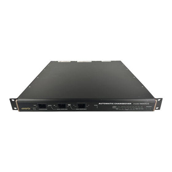
Model 5600ACO
Automatic Changeover
Instruction Manual
Fax: 905-335-3573
Fax: 905-335-0909
Copies of this manual can be ordered from your Evertz dealer or from Evertz
Version 1.5
Model 5600ACO Automatic Changeover Unit
Evertz Microsystems
Advertisement
Table of Contents

Related Manuals for evertz 5600ACO


Summary of Contents for evertz 5600ACO
- Page 1 Web Page: http://www.evertz.com Version 1.5 June 2005 The material contained in this manual consists of information that is the property of Evertz Microsystems and is intended solely for the use of purchasers of the 5600ACO Automatic Changeover. Evertz Microsystems expressly prohibits the use of this manual for any purpose other than the operation of the 5600ACO.
- Page 2 Model 5600ACO Automatic Changeover Unit This page left intentionally blank Version 1.5...
- Page 3 Model 5600ACO Automatic Changeover Unit IMPORTANT SAFETY INSTRUCTIONS The lightning flash with arrowhead symbol within an equilateral triangle is intended to alert the user to the presence of uninsulated “Dangerous voltage” within the product’s enclosure that may be of sufficient magnitude to constitute a risk of electric shock to persons.
- Page 4 WARNING Changes or Modifications not expressly approved by Evertz Microsystems Ltd. could void the user’s authority to operate the equipment. Use of unshielded plugs or cables may cause radiation interference. Properly shielded interface cables with the shield connected to the chassis ground of the device must be used Version 1.5...
- Page 5 Evertz products are for informational use only and are not warranties of future performance, either express or implied. The only warranty offered by Evertz in relation to this product is the Evertz standard limited warranty, stated in the sales contract or order confirmation form.
- Page 6 Model 5600ACO Automatic Changeover Unit This page left intentionally blank Version 1.5...
-
Page 7: Table Of Contents
Model 5600ACO Automatic Changeover Unit TABLE OF CONTENTS OVERVIEW ..........................1-1 1.1. HOW TO USE THIS MANUAL.................... 1-3 INSTALLATION ........................... 2-1 2.1. REAR PANEL ........................2-1 2.1.1. Coaxial Connections ....................2-1 2.1.2. Linear Time Code, Parallel Remote Control and Auxiliary Connections....2-1 2.1.3. - Page 8 Table 3-4: Primary Reference Mode Switch Settings ..................3-4 Table 3-5: GPI Input Mode Switch Settings ....................3-5 Table 3-6: Single GPI mode operation......................3-5 Table 3-7: Dual GPI mode operation ......................3-5 Table 4-1: 7700 Series or 5600ACO Upgrade Cable (Evertz part #WA-S76)..........4-3 Version 1.5...
-
Page 9: Overview
(LTC) to each of the two Master 5600MSCs. Each 5600MSC Master offers two LTC outputs that may be used for different time codes. All four LTC signals are fed to the 5600ACO on two 'D' connectors, one for each Master. The LTC outputs from the selected master are available on two XLR connectors. -
Page 10: Figure 1-1: Redundant Master Clock/Spg With Auto Changeover System Diagram
Model 5600ACO Automatic Changeover Unit Features: • Relay switches for all the system critical outputs from two 5600MSC units • 8 video/sync/DARS or other coaxial signals • 10MHz frequency reference output • Time Code outputs • Automatic changeover is a voting system based on which source has the most valid signals and that the good signals on the present master are also on the backup. -
Page 11: How To Use This Manual
Model 5600ACO Automatic Changeover Unit 1.1. HOW TO USE THIS MANUAL This manual is organized into 4 chapters: Overview, Installation, Operation, and Technical Information. There are individual tables of contents at the beginning of each chapter as well as an overall table of contents at the beginning of the manual to aid in finding the information you want. - Page 12 Model 5600ACO Automatic Changeover Unit This page left intentionally blank OVERVIEW Page 1-4 Version 1.5...
-
Page 13: Installation
2.5 give more detail on connecting the system. 2.1.1. Coaxial Connections There are 8 groups of 3 BNC connectors on the 5600ACO rear panel. In each group there is one labelled A, another labelled B for connection of the indicated signal from the respective 5600MSC Master Clock/SPG. -
Page 14: Power Connections
2.2. MOUNTING The 5600ACO is equipped with rack mounting angles and fits into a standard 19 inch by 1 3/4 inch (483 mm x 45 mm) rack space. The mounting angles may be removed if rack mounting is not desired. -
Page 15: Power Requirements
2.4.2. 10 MHz Output Connect the 10 MHz output of the Master A 5600MSC unit to the A 10 MHz input of the 5600ACO. Connect the 10 MHz output of the Master B 5600MSC unit to the B 10 MHz input of the 5600ACO. -
Page 16: Ltc And Gpio Connections
2.4.4. LTC and GPIO Connections Connect the AUX I/O output of the Master A 5600MSC unit to the A AUX I/O input of the 5600ACO using one of the straight through interconnect cables provided. Connect the AUX I/O output of the Master B 5600MSC unit to the B AUX I/O input of the 5600ACO using one of the straight through interconnect cables provided. -
Page 17: Connecting The General Purpose Inputs And Outputs
Auto changeover, as well as the GPI inputs and Outputs from the two 5600MSC units. The signals on the top row of the connector are for the 5600ACO only and do not connect to the 5600MSC units. (see section 3.3) The signals on the bottom row of the connector are connected directly to the 5600MSC units (see section 2.4.4). -
Page 18: Connecting 500Aco2-Hd/Sd Auto Changeover Modules
ACO GPI1 and ACO GPI2 inputs. The 5600ACO will decide if a changeover is necessary based on all the inputs on the 5600ACO, and the ACO GPI1 and ACO GPI2 inputs from all the 500ACO2-HD/SD connected on the wired ORed bus. The 5600ACO provides control of the 500ACO2-HD/SD module’s switches by means of the ACO GPO1 output. -
Page 19: Figure 2-4: Aco Extension Mode Diagram
Model 5600ACO Automatic Changeover Unit GPI2 5600ACO GPI1 GPO1 GPO1 GPO2 GPO1 GPO2 GPO1 GPO2 ..5002ACO-HD/SD 500ACO2-HD/SD 500ACO2-HD/SD unit n unit 1 unit 2 GPI1 GPI1 GPI1 Figure 2-4: ACO Extension Mode Diagram INSTALLATION Page 2-7 Version 1.5... - Page 20 Model 5600ACO Automatic Changeover Unit This page left intentionally blank INSTALLATION Page 2-8 Version 1.5...
-
Page 21: How To Operate The Automatic Changeover
The front panel controls consist of three recessed rocker switches to select the operating mode of the changeover and 30 LED status indicators. 3.1. AN OVERVIEW OF THE STATUS INDICATORS There are 30 status indicators located on the front panel that show operational status of the 5600ACO at a glance. 3.1.1. Operating Mode Indicators AUTO This green LED will be On when the unit is operating in the Automatic control mode. -
Page 22: Input Indicators
CHANGEOVER MODE switch is set in the Auto position, the 5600ACO will decide whether to select the A or B inputs based on all the inputs on the 5600ACO, and the ACO GPI1 and ACO GPI2 inputs from all the 500ACO2-HD/SD connected on the wired ORed bus. -
Page 23: Manual Gpi Changeover Mode
DIP switch 1 must also be set in the Off (open) position to enable GPI changeover mode. The 5600ACO will decide whether to select the A or B inputs based on the ACO GPI1 input on the top row of the terminal strip on the rear panel. -
Page 24: Setting The Switchover Detection Speed
Model 5600ACO Automatic Changeover Unit There is an 8 position DIP switch located on the main circuit card inside the 5600ACO. The ON position is closest to the PCB. Table 3-2 shows the assigned DIP switch functions. DIP Switch Function... -
Page 25: Gpi Inputs
Table 3-6: Single GPI mode operation In single GPI mode the 5600ACO is controlled by the ACO GPI1 input on the top row of the terminal strip on the rear panel. GPI2 is not used in this mode. When GPI1 is low Master A will be selected. -
Page 26: Gpo Tally Outputs
The default condition of the 5600ACO relays when there is no power applied is that the Master that was last active will be selected and GPO2 will be connected to ground. -
Page 27: Technical Description
GPI1, GPI2: Tally inputs from 500ACO2-HD/SD modules Outputs: GPO1: Low: Master A is selected (default when the 5600ACO has no power) High Master B is selected GPO2: Low: Master A & Master B differ or PSU failure High: Master A and B have equivalent signals... -
Page 28: Msc General Purpose Inputs And Output
Model 5600ACO Automatic Changeover Unit 4.1.4. MSC General Purpose Inputs and Output Inputs: 2 GPI inputs connected to both Master A and Master B Outputs: 2 GPI outputs connected from Master A through AUXI/O A 2 GPI outputs connected from Master B through AUXI/O B... -
Page 29: Changing The Fuses
Special upgrade cable (Evertz part #WA S76). This cable is the same as the standard upgrade cable used with Evertz 7700 series or 500 series modules and can be found in the vinyl pouch at the front of the modular system binder. Alternately you can make your own cable with the pinout shown in Table 4-1. -
Page 30: Terminal Program Setup
1. Connect the Serial Upgrade cable to the 2 row x 3 pin header J34 on the main circuit board of the 5600ACO. The 2 x 3 pin header end should be keyed so that you do not insert it in the wrong direction. -
Page 31: Initiating Firmware Upgrade Mode From The Terminal Program
Model 5600ACO Automatic Changeover Unit 4.2.2.3. Initiating Firmware Upgrade Mode From The Terminal Program 7. After the unit powers up, a banner with the boot code version information should appear in the terminal window. The cursor at the left side of the screen should be spinning. -
Page 32: Uploading The New Firmware
10 minutes the unit’s Boot code will time out. You can restart the upgrade process by power cycling the unit. The 5600ACO application firmware the bin file will have a name something like 1v41_1_5600ACO.bin The numbers at the beginning of the file name indicate the version of the firmware.
Need help?
Do you have a question about the 5600ACO and is the answer not in the manual?
Questions and answers