Table of Contents
Advertisement
Quick Links
© Copyright 2004 - 2017
EVERTZ MICROSYSTEMS LTD.
5288 John Lucas Drive
Burlington, Ontario
Canada L7L 5Z9
Phone:
905-335-3700
Sales:
sales@evertz.com
Tech Support: service@evertz.com
Web Page:
http://www.evertz.com
Version 1.2, September 2017
The material contained in this manual consists of information that is the property of Evertz Microsystems and is intended solely for the use of
purchasers of the 5601ACO2 Automatic Changeover. Evertz Microsystems expressly prohibits the use of this manual for any purpose other
than the operation of the 5601ACO2.
All rights reserved. No part of this publication may be reproduced without the express written permission of Evertz Microsystems Ltd. Copies
of this manual can be ordered from your Evertz dealer or from Evertz Microsystems.
5601ACO2
Automatic Changeover
Instruction Manual
Fax: 905-335-3573
Fax: 905-335-7571
Advertisement
Table of Contents

Related Manuals for evertz 5601AC02


Summary of Contents for evertz 5601AC02
- Page 1 Version 1.2, September 2017 The material contained in this manual consists of information that is the property of Evertz Microsystems and is intended solely for the use of purchasers of the 5601ACO2 Automatic Changeover. Evertz Microsystems expressly prohibits the use of this manual for any purpose other than the operation of the 5601ACO2.
- Page 2 This page left intentionally blank...
- Page 3 IMPORTANT SAFETY INSTRUCTIONS The lightning flash with arrowhead symbol within an equilateral triangle is intended to alert the user to the presence of uninsulated “Dangerous voltage” within the product’s enclosure that may be of sufficient magnitude to constitute a risk of electric shock to persons. The exclamation point within an equilateral triangle is intended to alert the user to the presence of important operating and maintenance (Servicing) instructions in the literature accompanying the product.
- Page 4 WARNING Changes or modifications not expressly approved by Evertz Microsystems Ltd. could void the user’s authority to operate the equipment. Use of unshielded plugs or cables may cause radiation interference. Properly shielded interface cables...
- Page 5 Evertz products are for informational use only and are not warranties of future performance, either expressed or implied. The only warranty offered by Evertz in relation to this product is the Evertz standard limited warranty, stated in the sales contract or order confirmation form.
- Page 6 Model 5601ACO2 Automatic Changeover Unit This page left intentionally blank Revision 1.2...
-
Page 7: Table Of Contents
Model 5601ACO2 Automatic Changeover Unit TABLE OF CONTENTS OVERVIEW ..........................1-1 1.1. HOW TO USE THIS MANUAL ................... 1-4 INSTALLATION.......................... 2-1 2.1. REAR PANEL ........................2-1 2.1.1. Coaxial Connections ....................2-1 2.1.2. Balanced AES, DARS and Analog Audio Connections ........... 2-2 2.1.3. - Page 8 Model 5601ACO2 Automatic Changeover Unit TECHNICAL DESCRIPTION ...................... 4-1 4.1. Auto Changeover Switch Criteria ................... 4-1 4.2. Change Limiting Operation ..................... 4-1 4.2.1. One Change Mode ....................4-2 4.2.2. Dual Change Mode ....................4-2 4.2.3. Unlimited Change Mode ..................4-3 4.3.
- Page 9 Model 5601ACO2 Automatic Changeover Unit 5.4.6. DARS Voting ......................5-5 5.4.7. LTC Voting ......................5-5 5.4.8. GPO Voting ......................5-6 5.5. Monitoring the GPO Status ..................... 5-6 5.5.1. GPO Status Tab ..................... 5-6 5.6. 5601ACO2 Fault Trap Controls ..................5-7 5.6.1.
- Page 10 Model 5601ACO2 Automatic Changeover Unit This page left intentionally blank Page iv CONTENTS Revision 1.2...
-
Page 11: Overview
Model 5601ACO2 Automatic Changeover Unit OVERVIEW The 5601ACO2 Automatic Changeover is intended to be connected directly to two 5601MSC Master Clock / Sync Generators as shown in Figure 2-2. The 5601ACO2 system uses latching relays to ensure maximum reliability and minimal disruption in the event of any failure. The complete system provides the highest level of security for television station video and time synchronization systems. - Page 12 Hot swappable redundant power supply standard • VistaLINK capable offering remote monitoring and configuration capabilities via SNMP using the ® model 9000NCP Network Control Panel or Evertz VistaLINK PRO or other third party SNMP ® manager software. Signal Type Inputs...
-
Page 13: Figure 1-1: 5601Aco2 Block Diagram
Model 5601ACO2 Automatic Changeover Unit Internal Latching termination Relays (not on 3G/ HD/SD) 3G/HD/SD (8), SYNC (6), ATG(2), 10MHz, Latching 3G/HD/SD (8), WORDCLOCK, 3G/HD/SD EQ, VIDEO Relays SYNC (6), SYNC Slicer, 10MHz, UNBAL. AES (2) ATG(2), 10MHz, WORDCLOCK Slicer 6 dB UNBAL.DARS WORDCLOCK, attenuatorn... -
Page 14: How To Use This Manual
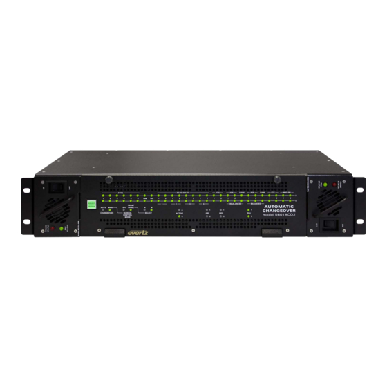
Model 5601ACO2 Automatic Changeover Unit Figure 1-2: Front View of Frame 1.1. HOW TO USE THIS MANUAL This manual is organized into 5 chapters: Overview, Installation, Operation, Technical Information, and VistaLINK Configuration and Control. The overview section provides a brief summary of the ®... -
Page 15: Installation
Model 5601ACO2 Automatic Changeover Unit INSTALLATION 2.1. REAR PANEL Figure 2-1: 5601ACO2 Rear Panel The following sections describe the purpose of the rear panel connectors of the 5601ACO2. Sections 2.1.1 to 2.1.4 describe the specific signals that should be connected to the 5601ACO2. Sections 2.4 and 2.5 give more detail on connecting the system. -
Page 16: Balanced Aes, Dars And Analog Audio Connections
Model 5601ACO2 Automatic Changeover Unit 2.1.2. Balanced AES, DARS and Analog Audio Connections DARS/AES/ANALOG: These 16 pin terminal strips are for connecting the balanced version of the AES and DARS signals as well as two balanced analog audio signals. The output cables can be secured into the removable portion of the terminal strips using a small screwdriver. -
Page 17: Ethernet Connections
Model 5601ACO2 Automatic Changeover Unit MSC: The bottom row of the 16 pin terminal strip has the two GPI Outputs from the A and B 5601MSC units and a pair of GPI inputs that will be connected to both the A and B 5601MSC units. -
Page 18: Power Connections
Model 5601ACO2 Automatic Changeover Unit Note the following cabling information for this wiring guide: • Only two pairs of wires are used in the 8-pin RJ 45 connector to carry Ethernet signals. • Even though pins 4, 5, 7 and 8 are not used, it is mandatory that they be present in the cable. •... -
Page 19: 5601Msc Connections
Model 5601ACO2 Automatic Changeover Unit 2.4. 5601MSC CONNECTIONS The 5601MSC unit connected to the A inputs of the 5601ACO2 will be called Master A. The 5601MSC unit connected to the B inputs of the 5601ACO2 will be called Master B. Audio Out LTC Input LTC 1 Out... -
Page 20: Sync Outputs
Model 5601ACO2 Automatic Changeover Unit 2.4.1. Sync Outputs Connect the six Sync outputs of the Master A 5601MSC unit to the A Sync inputs of the 5601ACO2. Connect the six Sync outputs of the Master B 5601MSC unit to the B Sync inputs of the 5601ACO2. Connect the Sync outputs of the 5601ACO2 to your plant distribution amplifier system. -
Page 21: Video Test Signal Generator Outputs
Model 5601ACO2 Automatic Changeover Unit 2.4.6. Video Test Signal Generator Outputs Connect the Analog TG outputs of the Master A 5601MSC unit to the A Analog TG1 and Analog TG2 inputs of the 5601ACO2. Connect the Analog TG1 AND Analog TG2 outputs of the Master B 5601MSC unit to the B Analog TG1 and Analog TG2 inputs of the 5601ACO2. -
Page 22: Synchronizing The Menu Settings Of The Two 5601Msc Units
Model 5601ACO2 Automatic Changeover Unit 2.4.8. Synchronizing the Menu Settings of the Two 5601MSC Units In the event of a changeover occurrence, it is necessary that all outputs on one 5601MSC have the same timing as those on the other. Identical timing for both 5601MSCs is assured by locking both to the same frequency and phase source (i.e. -
Page 23: Figure 2-4: Gpo1 Output Circuitry
Model 5601ACO2 Automatic Changeover Unit 10 K GPO Pin from internal circuit Figure 2-4: GPO1 Output Circuitry + 5 VDC 10 K ohm from internal GPO Pin circuit 10 ohm Figure 2-5: GPO2 Output Circuitry INSTALLATION Page 2-9 Revision 1.2... - Page 24 Model 5601ACO2 Automatic Changeover Unit This page left intentionally blank Page 2-10 INSTALLATION Revision 1.2...
-
Page 25: How To Operate The Automatic Changeover
Model 5601ACO2 Automatic Changeover Unit HOW TO OPERATE THE AUTOMATIC CHANGEOVER The front panel controls consist of three recessed rocker switches to select the operating mode of the changeover and 70 LED status indicators. SYNC 3 G/ HD/ SDI TG DARS DARS MSC GPI... -
Page 26: Input Indicators
Model 5601ACO2 Automatic Changeover Unit 3.1.2. Input Indicators A INPUTS: These twenty-eight green LEDs indicate that the respective input signals from the Master A device are present and valid. If the LED is excluded from the voting pool, the LED will be dim. B INPUTS: These twenty-eight green LEDs indicate that the respective input signals from the Master B device are present and valid. -
Page 27: Automatic Changeover Mode
Model 5601ACO2 Automatic Changeover Unit The 5601ACO2 changeover uses latching relays that retain their state when there is no power applied. When there is no power applied to the 5601ACO2, GPO2 will be connected to ground indicating a fault condition. Figure 3-2: Front Panel &... -
Page 28: Manual Switch Changeover Mode
Model 5601ACO2 Automatic Changeover Unit 3.2.3. Manual Switch Changeover Mode To operate the 5601ACO2 in Manual Front Panel mode, push the CHG OVER switch to the Manual position and the CTL SEL mode switch to the FP (Front Panel) position. The Manual and Front Panel LEDs will come on. -
Page 29: Table 3-2: Gpi Input Mode Switch Settings
Model 5601ACO2 Automatic Changeover Unit 3.3.1. GPI Input Mode DIP Switch 1 is used to select one of two modes of operation for Manual GPI changeover mode. (See section 3.2.2 for more information about Manual GPI changeover mode) DIP 1 GPI Input Mode GPI Changeover Mode –... -
Page 30: Changeover Rate
Model 5601ACO2 Automatic Changeover Unit 3.3.2. Changeover Rate DIP switch 2 controls the speed of the decision process before a changeover is made. DIP 2 Changeover Rate Off (Up) Changeover in 250mS On (Down) Changeover in 100mS Table 3-5: Changeover Rate Switch Settings When DIP switch 2 is in the Off position, the ACO takes approximately 250 msec. -
Page 31: Gpo Tally Outputs
Model 5601ACO2 Automatic Changeover Unit When DIP switch 8 and DIP switch 7 are in the Off position, the 5601ACO2 may change an unlimited number of times depending on inputs when in automatic mode. When DIP switch 7 is in the On position and DIP switch 8 is in the off position, and in automatic mode, only 1 change will be allowed if they occur within 0.5 seconds. - Page 32 Model 5601ACO2 Automatic Changeover Unit This page left intentionally blank Page 3-8 OPERATION Revision 1.2...
-
Page 33: Technical Description
Model 5601ACO2 Automatic Changeover Unit TECHNICAL DESCRIPTION 4.1. Auto Changeover Switch Criteria Understanding how the ACO makes its changeover switch decisions is vital to designing, monitoring, and troubleshooting a synchronizing signal distribution system. This section provides information on how the ACO determines when it is time to switch to the other input. All inputs, except for analog audio, have signal presence detectors that determine if there is a valid signal present on that input. -
Page 34: One Change Mode
Model 5601ACO2 Automatic Changeover Unit There are three automatic modes of operation: Switch one time only, on the first valid switch One Change Mode: criteria. Dual Change Mode: Suspend all switching when two consecutive criteria are met within a short time period. Unlimited Change Mode: Switch whenever a valid criterion is met. -
Page 35: Switching Decision Tree
Model 5601ACO2 Automatic Changeover Unit Multiple changeover events, separated by more than approximately half a second are considered valid conditions for ACO operation. This is the recommended operating mode because it offers normal operation while minimizing system impact in the event of an output short. 4.2.3. -
Page 36: Specifications
Model 5601ACO2 Automatic Changeover Unit 4.4. SPECIFICATIONS 4.4.1. LTC Outputs Standard: SMPTE 12M frame rate set by 5601MSC Number of outputs: 2 Connectors: 3 pin male XLR type outputs Signal Level: Set in 5601MSC 4.4.2. Coaxial Inputs and Outputs Type: Depends on signal connected from 5601MSC SD/HD/3G SDI, DARS, bi-level or tri-level sync, colour black, 10 MHz, Word Clock... -
Page 37: Msc General Purpose Inputs And Outputs
Model 5601ACO2 Automatic Changeover Unit 4.4.5. MSC General Purpose Inputs and Outputs Inputs: 2 GPI inputs connected to both Master A and Master B Outputs: 2 GPI outputs connected from Master A through AUXI/O A 2 GPI outputs connected from Master B through AUXI/O B Connector: 6 pins on 16 pin removable terminal block Signal Level:... -
Page 38: Upgrading The Firmware
• “Straight-thru” serial extension cable (DB9 female to DB9 male) or (DB25 female to DB9 male). • Terminal program that is capable of Xmodem file transfer protocol. (such as HyperTerminal) • New firmware supplied by Evertz. 4.5.2. Terminal Program Setup 1. -
Page 39: Initiating Firmware Upgrade Mode From The Terminal Program
“UPLOAD FILE NOW, CONTROL-X TO CANCEL” For example: EVERTZ MCF5272 MONITOR 2.3 BUILD 3 (66 MHZ) COPYRIGHT 1997, 1998, 1999, 2000, 2001, 2002 EVERTZ MICROSYSTEMS LTD. 28F160C3B FLASH DETECTED BRD=5601ACO2 MODEL=BA5601ACO2 PROD=5601ACO2... -
Page 40: Completing The Upgrade
Model 5601ACO2 Automatic Changeover Unit 4. The following is a list of possible reasons for a failed upload: • If you get the message "transfer cancelled by remote" you must restart the terminal program and load the bin file, then remove and install the module again. •... -
Page 41: Network Configuration
Model 5601ACO2 Automatic Changeover Unit 4.6.1. Network Configuration 1) Network Configuration - set the IP parameters for this 5601ACO2 ip address: 192.168.1.200 netmask address: 255.255.255.0 gateway: 0.0.0.0 broadcast address: 192.168.1.255 DHCP enabled: False ---------------------------------- (1) Set IP Address (2) Set Netmask (3) Set Gateway (4) Set Broadcast Address (5) Use DHCP... -
Page 42: Voting Control
Model 5601ACO2 Automatic Changeover Unit 4.6.3. Voting Control 3) Voting Control – set which input channel pair is included in the voting pool. Note that item 25 is the global enable for items 1 through 24. If 25 is set to Yes, then voting will be determined by the settings of items 1 through 24. -
Page 43: Show Status
Model 5601ACO2 Automatic Changeover Unit 4.6.4. Show Status 4) Show Status – shows a synopsis of all of the above 3 items, and also shows the status of all input channels. There are no settable controls under this menu item. ---------------------------------- Trap destinations Trap Destination 1: 192.168.192.215... -
Page 44: Upgrade
Model 5601ACO2 Automatic Changeover Unit 4.6.5. Upgrade 5) Upgrade – enters an upgrade mode for firmware upgrades. If entered you will be prompted again to be sure you wish to do an upgrade. See section 4.5.4 above for details on how to complete the upgrade. -
Page 45: Vistalink Configuration And Control
3. A virtual database, known as the Management Information Base (MIB), lists all the variables being controlled, which both the Manager and Agent understand. Please contact Evertz for further information about obtaining a copy of the MIB for interfacing to a third party Manager/NMS. -
Page 46: Using Vistalink
Model 5601ACO2 Automatic Changeover Unit 5.1.2. Using VistaLINK to Configure the 5601ACO2 ® The 5601ACO2 should be auto-discovered by VistaLINK PRO and appear under the Hardware ® section of the VistaLINK PRO Navigation Tree named with its given IP Address. If the 5601ACO2 is ®... -
Page 47: Monitoring The 5601Aco2 Using The General Status Tab
Model 5601ACO2 Automatic Changeover Unit 5.3. Monitoring the 5601ACO2 using the General Status Tab The General Status tab enables the user to view the status of various parameters for the 5601ACO2. These status conditions will not be updated live unless the auto refresh is enabled. Figure 5-2: VistaLINK Monitoring –... -
Page 48: Configuring The Voting Control
Model 5601ACO2 Automatic Changeover Unit 5.4. Configuring the Voting Control The Voting Control settings are used to configure how the 5601ACO2 makes decisions regarding valid signals. It also decides when to switch to the backup signals. Figure 5-3: VistaLINK Monitoring – Voting Control ®... -
Page 49: General Parameters
Model 5601ACO2 Automatic Changeover Unit 5.4.2. General Parameters 10Mhz Voting: If set to include, the 10Mhz input status will be included in the voting process. If set to exclude, the input will not be included in the process. Word Clock Voting: If set to include, the Word Clock input status will be included in the voting process. -
Page 50: Gpo Voting
Model 5601ACO2 Automatic Changeover Unit 5.4.8. GPO Voting For brevity, only Channel 1 (GPO 1) will be discussed in the manual. Channel 1: If set to include, Channel 1 will be included in the voting process. If set to exclude, the input will not be included in the process. -
Page 51: 5601Aco2 Fault Trap Controls
Model 5601ACO2 Automatic Changeover Unit 5.6. 5601ACO2 Fault Trap Controls Figure 5-5 to Figure 5-10 show the six tabs used to determine which SNMP trap messages will be sent by the 5601ACO2. 5.6.1. Setting the Analog Faults The Analog Faults control, as illustrated in Figure 5-5, allows the user to enable or disable Analog TG traps and view trap status. -
Page 52: Setting The 3G Hd Sdi Tg Faults
Model 5601ACO2 Automatic Changeover Unit 5.6.2. Setting the 3G HD SDI TG Faults This control, as illustrated in Figure 5-6, allows the user to enable 3G HD SDI TG traps and monitor the trap status. To enable a particular trap, simply click the box located beside each trap so that a check- mark appears. -
Page 53: Setting The Aes Dars Faults
Model 5601ACO2 Automatic Changeover Unit 5.6.3. Setting the AES DARS Faults As illustrated in Figure 5-7, this control allows the user to enable AES DARS traps and monitor the trap status. To enable a particular trap, simply click the box located beside each trap so that a check-mark appears. -
Page 54: Setting The Msc Gpo Faults
Model 5601ACO2 Automatic Changeover Unit Figure 5-8: VistaLINK Monitoring – LTC Faults ® 5.6.5. Setting the MSC GPO Faults This control, as illustrated in Figure 5-9, allows the user to enable MSC GPO traps and monitor the trap status. To enable a particular trap, simply click the box located beside each trap so that a check-mark appears. -
Page 55: Configuring The Faults Tab
Model 5601ACO2 Automatic Changeover Unit 5.6.6. Configuring the Faults Tab The Faults tab, as illustrated in Figure 5-10, allows the user to enable a variety of traps such as Ten MHz, Word Clock, Current Output, Power Supply, Fan, Door Open traps. To enable a particular trap, simply click the box located beside each trap so that a check-mark appears. - Page 56 Model 5601ACO2 Automatic Changeover Unit This page left intentionally blank Page 5-12 VistaLINK CONFIGURATION Revision 1.2 ®...
Need help?
Do you have a question about the 5601AC02 and is the answer not in the manual?
Questions and answers