Table of Contents

Subscribe to Our Youtube Channel
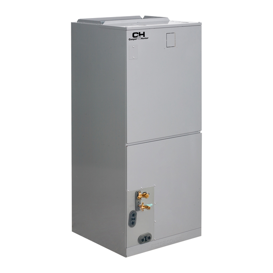
Related Manuals for Cooper & Hunter CH-M18AHU


Summary of Contents for Cooper & Hunter CH-M18AHU
- Page 1 AIR-HANDLER AIR CONDITIONERS Owner’s Manual & Installation Manual MODELS: CH-M18AHU CH-M24AHU IMPORTANT NOTE: Read this manual carefully before installing or operating your new air conditioning unit. Make sure to save this manual for future reference.
-
Page 2: Table Of Contents
Table of Contents Safety Precautions ................04 Owner’s Manual Indoor Unit Parts And Major Functions ..........08 1. Unit Parts..............................08 2. Operating Conditions..........................08 3. Features ..............................09 4. Energy Saving Tips..........................09 Care and Maintenance ..............10 Troubleshooting ................12... - Page 3 Installation Manual Accessories ..................15 Indoor Unit Installation ..............16 1. Indoor Unit Parts ..........................16 2. Safety Precautions ...........................16 3. Indoor Unit Installation Instructions ......................16 4. Installation of Electric Auxiliary Heat Module ......................23 ..............28 Outdoor Unit Installation ........................28 1. Select installation location .............................29 2.
-
Page 4: Safety Precautions
Safety Precautions Read Safety Precautions Before Operation and Installation Incorrect installation due to ignoring instructions can cause serious damage or injury. The seriousness of potential damage or injuries is classified as either a WARNING or CAUTION. CAUTION WARNING This symbol indicates the possibility of This symbol indicates the possibility of personnel injury or loss of life. - Page 5 CLEANING AND MAINTENANCE WARNINGS Turn off the device and disconnect the power before cleaning. Failure to do so can cause electrical • shock. Do not clean the air conditioner with excessive amounts of water. • Do not clean the air conditioner with combustible cleaning agents. Combustible cleaning agents •...
-
Page 6: Owner's Manual
WARNINGS FOR PRODUCT INSTALLATION 1. Installation must be performed by an authorized dealer or specialist. Defective installation can cause water leakage, electrical shock, or fire. 2. Installation must be performed according to the installation instructions. Improper installation can cause water leakage, electrical shock, or fire. (In North America,installation must be performed in accordance with the requirement of NEC and CEC by authorized personnel only.) 3. - Page 7 Disposal Guidelines This marking shown on the product or its literature, indicates that waste electrical and eletrical equipment should not be mixed with general household waste. Correct Disposal of This Product (Waste Electrical & Electronic Equipment) This appliance contains refrigerant and other potentially hazardous materials. When disposing of this appliance, the law requires special collection and treatment.
-
Page 8: Indoor Unit Parts And Major Functions
Indoor Unit Parts And Major Functions Unit Parts Operating Conditions Use the system under the following temperatures for safe and effective operation. If the air conditioner is used under different conditions, it may malfunction or become less efficient. Air outlet Inverter Split Type COOL mode HEAT mode... -
Page 9: Features
To further optimize the performance of your unit, do the following: Keep doors and windows closed. • Limit energy usage by using TIMER ON and TIMER OFF functions. • Do not block air inlets or outlets. • Regularly inspect and clean air filters. •... -
Page 10: Care And Maintenance
Care and Maintenance Cleaning Your Indoor Unit WARNING: DO NOT REMOVE OR CLEAN THE FILTER BY YOURSELF BEFORE CLEANING OR Removing and cleaning the filter can be dangerous. MAINTENANCE Removal and maintenance must be performed by ALWAYS TURN OFF YOUR AIR CONDITIONER a certified technician. - Page 11 Maintenance – CAUTION Long Periods of Non-Use Before changing the filter or cleaning, • turn off the unit and disconnect its power If you plan not to use your air conditioner for an supply. extended period of time, do the following: When removing filter, do not touch metal •...
-
Page 12: Troubleshooting
Troubleshooting SAFETY PRECAUTIONS If any of the following conditions occurs, turn off your unit immediately! The power cord is damaged or abnormally warm • You smell a burning odor • The unit emits loud or abnormal sounds • A power fuse blows or the circuit breaker frequently trips •... - Page 13 Issue Possible Causes The outdoor unit The unit will make different sounds based on its current operating mode. makes noises Dust is emitted from The unit may accumulate dust during extended periods of non-use, which will be emitted either the indoor or when the unit is turned on.
- Page 14 Problem Possible Causes Solution Wait for the power to be restored Power failure The power is turned off Turn on the power The unit is not The fuse is burned out Replace the fuse working The Unit’s 3-minute protection Wait three minutes after restarting has been activated the unit Turn timer off...
-
Page 15: Accessories
Accessories The air conditioning system comes with the following accessories. Use all of the installation parts and accessories to install the air conditioner. Improper installation may result in water leakage, electrical shock and fire, or equipment failure. Accessories (Packed with the indoor unit) Name Shape Quantity... -
Page 16: Indoor Unit Installation
Indoor Unit Installation Indoor Unit Parts IMPORTANT Please apply sealant around the places where the wires, refrigerant pipes and condensate coil compartment (Access panel Removed) pipes enter the cabinet. Upflow drain pan Indoor Unit Installation Instructions The indoor unit should be installed in a location that meets the following requirements: Horizontal drain pan Enough room for installation and maintenance. - Page 17 Fixing instructions: When installed vertically IMPORTANT (upward or downward), the lower end of the air Use duct tape and/or Permagum to seal closed outlet needs to be connected to the L-shaped any space around the holes where the drain lines metal air duct and fastened by screws.
- Page 18 (unit: inch/mm) Use flexible duct collars to minimize the transmission Recommended size of lter of vibration/noise into the conditioned space. Where return air duct is short, or where sound is liable to be a problem, sound absorbing glass fiber should be used inside the duct. Insulation of duct work is a must where it runs through an uncooled Model A(for North America models)...
- Page 19 Horizontal installations Vertical up and horizontal left installation NOTE: does not need to change thedirection of evaporator. Indication of the position of each temperature temperature sensor of the evaporator: 12-24K model NOTE: For installation, an drain pan (not supplied) must be installed. The unit may be installed in one of the upflow, downflow, horizontal left or horizontal right orientations .
- Page 20 3. Remove evaporator cover plate. Regular installation instructions Please follow these steps to perform Vertical up installation and Horizontal left installation: 1. Open the upper cover. 2. Open the cover of the electronic control box. 3. Connect the wire according to the wiring diagram.
- Page 21 5. Remove T1、T2 temperature sensor and 8. Reinstall the evaporator and drain pan. electronic expansion valve wire ties. 9. Reinstall T1, T2 temperature sensor plug electronic expansion valve and tie up the temperature sensor wires. NOTE: The wire body needs to pass through the 6.
- Page 22 11. Reinstal evaporator cover plate. Hook the wire into the buckle and go down from the wire slot. Sponge paste reset. 12. Connect the wire according to the wiring diagram. 10. The evaporator is assembled in place. 13. Reassemble the upper cover. Use cable ties to bind and 14.
-
Page 23: Installation Of Electric Auxiliary Heat Module
Installation Requirements Installation of Electric Auxiliary Heat Module (for some models)(not supplied) Before installation, please check the list of electric auxiliary heat modules and physical objects. After Accessories transportation, check whether the electric heating is damaged. If any damage is found, please contact Name Shape Quantity... - Page 24 2. Remove the terminal block and power cord, 4. Tighten the fixing screws. loosen the screws, and remove the electric screws auxiliary heating cover. 5. Wiring according to the wiring nameplate. 3. Install the electric auxiliary heating component 6. Install the upper cover. into the chassis shell along the front direction, 7.
- Page 25 After the electric heating wiring is connected, please confirm before power on: Check all wiring and ensure reliable connection of wire body. Check the electric heating fixing screw, and the screw is fixed reliably. The size selection of power wire meets the power supply requirements.
- Page 26 Electric auxiliary heating wiring diagram 3KW/5KW HEAT KIT 8KW/10KW HEAT KIT :thermal cut-out :thermal cut-out :thermal link, self-resetting :thermal link, self-resetting Aux-Heat HTR1 control signal TCO1 0 0 0 0 0 0 0 0 0 0 0 0 0 0 0 0 BLACK TO INDOOR UNIT RELAY1...
- Page 27 Electric auxiliary heating wiring diagram 25KW HEAT KIT : thermal cut-out : thermal link, self-resetting HTR5 TCO5 8 8 8 8 8 8 8 8 8 8 8 8 8 8 8 8 6 6 6 6 6 6 6 6 6 6 6 6 6 6 6 6 RELAY5 BLACK 1 1 1 1 1 1 1 1 1 1 1 1 1 1 1 1 1 1 1 1 1 1 1 1 1 1 1 1 1 1 1...
-
Page 28: Outdoor Unit Installation
Outdoor Unit Installation install unit in the following locations: DO NOT Install the unit by following local switchs and Near an obstacle that will block air inlets and regulations , there may be differ slightly between outlets different regions. Near a public street, crowded areas, or where 24in (60cm) above noise from the unit will disturb others Near animals or plants that will be harmed by... -
Page 29: Install Drain Joint
Step 3: Anchor outdoor unit Step 2: Install drain joint (Heat pump unit only) The outdoor unit can be anchored to the ground or to a wall-mounted bracket with Before bolting the outdoor unit in place, you must bolt(M10). Prepare the installation base of install the drain joint at the bottom of the unit. - Page 30 (unit: inch/mm) If you will install the unit on the ground or on a concrete mounting platform, Outdoor Unit Dimensions Mounting Dimensions do the following: inch inch mm inch mm inch mm inch 1. Mark the positions for four expansion bolts 511 12-1/2 31-11/16 21-13/16...
-
Page 31: Drainpipe Installation
Drainpipe Installation Indoor Drainpipe Installation The drainpipe is used to drain water away from the unit. Improper installation may cause unit 1. Cover the drainpipe with heat insulation to and property damage. prevent condensation and leakage. CAUTION These units operate with a positive pressure at the drain connections and a drain trap is required. - Page 32 3. Pass the drain hose through the wall hole. Anti-syphon >2”(50mm) air vent Make sure the water drains to a safe location >2”(50mm) where it will not cause water damage or a >2”(50mm) Vent T Lean over slipping hazard. 1/50 Drain Trap NOTE: The drainpipe outlet should be at least 1.9”...
-
Page 33: Refrigerant Piping Connection
Refrigerant Piping Connection Safety Precautions CAUTION WARNING Oil traps If oil flows back into the outdoor unit’s • All field piping must be completed by a compressor, this might cause liquid compression licensed technician and must comply with or deterioration of oil return. Oil traps in the the local and national regulations. -
Page 34: Connection Instructions Refrigerant Piping
Name Shape Quantity(PC) Φ 1/4 i n(6.35) Liquid side Φ 3/8in(9.52) Parts you must purc hase Connecting pipe separately. Consult the dealer Φ 1/2in(12.7) assembly about the proper pipe size of Φ 5/8in(16) the unit you purchased. Gas side Φ 3/4in(19) Φ... - Page 35 5. Clamp flare form on the end of the pipe. NOTE: Use both a spanner and a torque wrench The end of the pipe must extend beyond the flare when connecting or disconnecting pipes to/from form. the unit. Flare form Pipe Place flaring tool onto the form.
- Page 36 After the unit is installed, Wrap the valve body 7. Thread this pipeline through the wall and with insulation material and make sure the valve connect it to the outdoor unit. is sealed. 8. Insulate all the piping, including the valves of the outdoor unit.
-
Page 37: Wiring
Wiring BEFORE PERFORMING ANY supply has been turned off. After turning off ELECTRICAL WORK, READ the power, always wait 10 minutes or more before you touch the electrical components. THESE REGULATIONS Make sure that you do not cross your 1. All wiring must comply with local and national electrical wiring with your signal wiring. -
Page 38: Outdoor Uint Wiring
Air switch (purchased seperately) Air switch (purchased seperately) Indoor unit power wires Electrical heater unit power wires Outdoor unit power wires Electrical Indoor unit heater Outdoor unit unit Indoor & Outdoor connective wires (purchased seperately) NOTE: The cographs are for explanation purpose only. Your machine may be slightly different. -
Page 39: Indoor Uint Wiring
WARNING 4. Clamp down the cable with the cable clamp. 5. Insulate unused wires with electrical tape. ISOLATE THE POWER SUPPLY LEADS AND Keep them away from any electrical or metal COMMUNICATION LEADS BY THE STRAIN parts. RELIF AND KEEP POWER SUPPLY LEADS 6. -
Page 40: Specific Wiring Method
CAUTION WARNING While connecting the wires, please strictly • Please refer to the wiring nameplate for the follow the wiring diagram. wiring method. Do not connect the power The refrigerant circuit can become very • cord to the communication line, as this may hot. - Page 41 Connection method C: • The fault warning Cooling and Fixed-speed Type Only System Wiring Diagram ALARM INDOOR UNIT OUTDOOR UNIT THERMOSTAT L1(C1) When there is a fault in the relay to close, otherwise the relay disconnected. This port is a BROWN BLACK passive outlet, you need to input a voltage...
-
Page 42: Control Logic
• Dehumidification control wiring Control Logic Indoor unit Connector Connector Purpose HUMIDISTAT First period cooling S4-1 DIP switch of Y/Y2 Second period cooling Perform disconnection and short-circuit to Heating(Four-way valve) achieve partition, control or dehumidifcation Heating operation Dehumidification control requires indirect Electric heating operation 1 Electric heating operation 2 humidifier at DH and R. -
Page 43: Dip Switch Definitions
DIP Switch Definitions Function DIP switch Address 24V thermostat interface DIP switch 24V control DIP switch Function DIP switch Static pressure DIP switch Page 43 ... - Page 44 Function DIP switch: • SW2-2, SW2-3: This two-digit dialing code can The dialing code mainly controls and selects the control the delayed start of electrically-assisted type of unit. It is suggested to adjust under the heat. guidance of the engineering staff. When the temperature difference is too large, the delayed start and the delayed start time can SW1-1: Switch communication mode function,...
- Page 45 Address DIP switch: Static pressure DIP switch: Address dialing S1+S2: When the user uses the centralized controller, the address dialing is This dialing code is only valid for 1-3. Composition required. of binary code, respectively corresponding to different wind profile static pressure. Network address: The address silkscreen is NET address, which is composed of a 16-bit address 000 is the default;...
- Page 46 Air volume table 000 gear (default) Model 001 air volume(CFM) 010 air volume(CFM) 011 air volume(CFM) air volume(CFM) 10KW 10KW 、8KW 5KW、3KW 15KW 15KW 、8KW 10KW、8KW 5KW、3KW 1100 1040 15KW 15KW 、10KW 10KW、8KW 8KW、5KW 1320 1255 1190 1125 20KW 15KW 10KW、8KW 8KW、5KW 1760...
- Page 47 Page 47 ...
-
Page 48: Air Evacuation
Air Evacuation Preparations and Precautions Close the Low Pressure side of the manifold gauge, and turn off the vacuum pump. Air and foreign matter in the refrigerant circuit can Wait for 5 minutes, then check that there cause abnormal rises in pressure, which can damage has been no change in system pressure. -
Page 49: Note On Adding Refrigerant
Note on Adding Refrigerant Some systems require additional charging depending on pipe lengths. The standard pipe length varies according to local regulations. For example, in North America, the standard pipe length is 25’ (7.5m). In other areas, the standard pipe length is 16‘5m (16‘). The refrigerant should be charged from the service port on the outdoor unit’s low pressure valve. -
Page 50: Test Run
Test Run 5. For the Outdoor Unit Before Test Run a. Check to see if the refrigeration system is A test run must be performed after the entire leaking. system has been completely installed. Confirm b. Make sure there is no vibration or the following points before performing the test: abnormal noise during operation. - Page 51 www.cooperandhunter.us LIMITED WARRANTY STATEMENT AIR HANDLER The warranty should be registered on our website www.cooperandhunter.us or by submitting the card below within 60 days of installation. The warranty is only valid when unit is installed by a licensed HVAC technician and registered within 60 days of installation date.
- Page 52 • Warranty applies only to air handler units which are installed and used exclusively with Cooper&Hunter equipment and accessories. Limited warranty applies only to systems that are properly installed by a state certi ed or licensed HVAC contractor • under applicable local and state law in accordance with all applicable building codes and permits; C&H installation and operation instructions and good trade practices.
- Page 53 The design and specifications are subject to change without prior notice for product improvement. Consult with the sales agency or manufacturer for details. Any updates to the manual will be uploaded to the service website, please check for the latest version. QS003UI-AHU 16123100000368 20211129...
Need help?
Do you have a question about the CH-M18AHU and is the answer not in the manual?
Questions and answers
Does this require vacuum before opening the valves? Page 36 step 9. Open the stop valves of the outdoor unit to start the flow of the refrigerant between the indoor and outdoor unit