Table of Contents
Advertisement
Quick Links
Advertisement
Table of Contents

Related Manuals for Cooper & Hunter CHML-ID09NK


Summary of Contents for Cooper & Hunter CHML-ID09NK
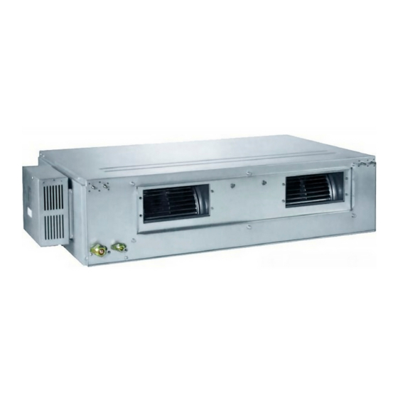
- Page 1 Installation and Operation Manual Free Match Series R410A Multi VFR System-Indoor Unit (For European Union) Applicable models : CHML-ID09NK CHML-ID12NK CHML-ID18NK CHML-ID21NK CHML-ID24NK Please read this manual carefully before the installation and operation of this product.
- Page 3 User Notice ◆ The total capacity of the indoor units which runs at the same time can not exceed 150% of that of the outdoor units; otherwise, the cooling (heating) effect of each indoor unit would be poor. ◆ Switch the main power on 8 hours before start the unit, helpful for a successful startup. ◆...
-
Page 4: Table Of Contents
Contents Ⅰ Safety Precautions ..................1 Ⅱ Installation Location and Matters Needing Attention ......... 2 1 How to select the installation location for the indoor unit ........2 2 Electric Wiring ..................... 2 3 Earthing Requirements ..................2 4 Accessories for Installation .................. 3 Ⅲ... -
Page 5: Ⅰ Safety Precautions
Safety Precautions Ⅰ Safety Precautions Please read this manual carefully before use and operate correctly as instructed in this manual. Please especially take notice of the following two symbols : Warning! It indicates improper operation which will lead to human casualty or sever injury. Cuation! It indicates improper operation which will lead to injury or property damage. -
Page 6: Ⅱ Installation Location And Matters Needing Attention
Installation Location and Matters Needing Attention Ⅱ Installation Location and Matters Needing Attention The installation of the unit must comply with the national and local safety regulations. The installation quality directly affects the normal use, so the user should not carry out the installation personally. -
Page 7: Accessories For Installation
Installation Location and Matters Needing Attention ① Running water pipe; ② Coal gas pipe; ③ Sewage pipe; ④ Other places where the professional personnel think unreliable. 4 Accessories for Installation Refer to the packing list for the accessories of the indoor and outdoor units respectively. -
Page 8: Ⅲ Installation Instructions
Installation Instructions Ⅲ Installation Instructions 1 Outline Dimension Drawings of the Indoor Unit Note: the unit in the followings figures is mm, unless otherwise specified. Fig.1 is applicable to CHML-ID09NK,CHML-ID12NKCHML-ID18NK, CHML-ID21NK, CHML-ID24NK Fig.1 Table 1: Outline Dimensions : Item Model... -
Page 9: Installation Of The Indoor Unit
Installation Instructions 3 Installation of the Indoor Unit a. Requirements on the Installation Location 1) Ensure the hanger is strong enough to withstand the weight of the unit. 2) The drainage of the drain pipe is easy. 3) No obstacle is in the inlet/outlet and the air circulation is in good condition. 4) Ensure the installation space shown in Fig.2 is left for the access to maintenance. -
Page 10: Horizontality Check Of The Indoor Unit
Installation Instructions If there is an opening in the ceiling, it is better to reinforce it to keep it flat and prevent it vibrating. ② . Consult the user and builder for more details. If the strength of the ceiling is not strong enough, a beam made of angle iron can be used and then fix ③... -
Page 11: Drawings Of The Air Supply Outlet And Return Air Inlet
Installation Instructions Fig.8 Name Name Hanger Transition Duct Return Air Duct Air Supply Duct Canvas Duct Diffuser Return Air Louver Diffuser Joint Air Supply Outlet Table 3 c. Installation Steps of the Round Air Supply Duct 1) Preinstall the outlet of the round duct on the transition duct and then fix it by the self-tapping screw. 2) Place the transition duct to the air outlet of the unit and fix it with rivet. -
Page 12: Installation Of The Return Air Duct
Installation Instructions Table 4 Dimensions of the Air Supply Outlet and Return Air Inlet (unit: mm) Air Supply Outlet Return Air Inlet Item Model CHML-ID09NK CHML-ID12NK CHML-ID18NK CHML-ID21NK 1062 CHML-ID24NK 7 Installation of the Return Air Duct a. The default installation location of the rectangular flange is in the back and the return air cover plate is in the bottom, as shown in Fig.11. -
Page 13: Installation Of The Condensate Pipe
Installation Instructions 8 Installation of the Condensate Pipe a. The condensate pipe should keep a inclination angle of 5~10° , which can facilitate the drainage of the condensate water. And the joints of the condensate pipe should be insulated by the insulation material to prevent condensing(see Fig.13). -
Page 14: Precautions For The Lift Pipe
Installation Instructions (Right) with a min. degree of slope 1/100 (Wrong) Fig.14 e. Insert the drain hose into the drain hole and tighten it with clamps. f. Wrap the clamps with large amount of sponge for thermal insulation. g. The drain hose inside the room also should be insulated. Clamp (accessory) Sponge (accessory) Clamp... -
Page 15: Test For The Drainage System
Installation Instructions I - Joint of drain pipe The specification of the joint of the drain pipe should be suitable to the running capacity of the unit Drain Hose (accessory) Fig.17 12 Test for the Drainage System a. After the electric installation, please take a test for the drainage system. b. -
Page 16: Insulation For The Refrigerant Pipe
Installation Instructions d. Wrap the exposed refrigerant pipe and the joints by sponge and then tighten them with the plastic tape. CUATION ! During the connection of the indoor unit and the refrigerant pipe, never pull any joints of the indoor ①... -
Page 17: Wiring Of The Power Cord (Single-Phase)
Installation Instructions crimpling pliers. 4) Let the screw go through the terminal of the multi-core wire and then fix it on the wiring board. Fig.20 WARNING! If the power cord or the signal line is damaged, they must be replaced with the dedicated one. ①... - Page 18 Installation Instructions CHML-U36NK4 POWER INDOOR UNIT C INDOOR UNIT A INDOOR UNIT D INDOOR UNIT B XT5X XT3X OUTDOOR UNIT Fig.21 CHML-U42NK5 POWER Fig.22...
-
Page 19: Wiring Of The Signal Line Of The Wired Controller
Table 7 Running Indoor Unit Current Input Power(W) Recommended Power Cord Power Cord (Sectional Indoor Area× Pieces) Type Model Cooling Heating Motor CHML-ID09NK 220-240V~ 50Hz 0.406 1.0×4 CHML-ID12NK 220-240V~ 50Hz 0.348 1.0×4 Cooling CHML-ID18NK 220-240V~ 50Hz 0.428 1080 1.0×4 Heating CHML-ID21NK 220-240V~ 50Hz 0.588... -
Page 20: Ⅳ Rated Working Conditions
Rated Working Conditions Ⅳ Rated Working Conditions Table 8 Working Temperature Range Indoor side state Outdoor side stae Dry bulb temp. ℃ Wet bulb temp. ℃ Dry bulb temp. ℃ Wet bulb temp. ℃ Rated Cooling Max. cooling Min. cooling —... -
Page 21: Ⅴ Error Analysis
Error Analysis Ⅴ Error Analysis If your conditioning unit runs abnormally, please check the following items before contact the maintenance serviceman. Table 9 Errors Possible Causes There is no power supply. Failed startup The breaker opens owing to electrical leakage. Voltage is too low. -
Page 22: Ⅵ Maintenance
Maintenance Ⅵ Maintenance CAUTION! Take notice of the following items before clean your air conditioning unit. Cut off the main power supply before contact any wiring device. ① . Only when the unit is turn off and the main power supply is cut off, can the unit be cleaned; otherwise ②...
Need help?
Do you have a question about the CHML-ID09NK and is the answer not in the manual?
Questions and answers