
Related Manuals for Cooper & Hunter CHML-U14NK2


Summary of Contents for Cooper & Hunter CHML-U14NK2
- Page 1 Service Manual Models: CHML-U14NK2 CHML-U18NK3 CHML-U21NK3 CHML-U24NK3 CHML-U28NK4 (Refrigerant R410A)
-
Page 2: Table Of Contents
Service Manual Table of Contents Part Ⅰ : Technical Information ................1 1. Summary ..........................1 2. Specifications ........................2 3. Outline Dimension Diagram ................12 4. Refrigerant System Diagram ................14 5. Electrical Part .........................15 5.1 Wiring Diagram ........................15 5.2 PCB Printed Diagram ......................20 6. -
Page 3: Part Ⅰ : Technical Information
Service Manual Part Ⅰ : Technical Information 1. Summary Outdoor Unit CHML-U14NK2 CHML-U18NK3 CHML-U21NK3 CHML-U24NK3 CHML-U28NK4 Technical Information... -
Page 4: Specifications
Service Manual 2. Specifications Model CHML-U14NK2(LCLH) CHML-U14NK2 Product Code CB228W06500 CB228W06501 Rated Voltage 220-240 220-240 Power Rated Frequency supply Phases Cooling capacity(max~min) 4100(2052~4396) 4100(2052~4396) Heating capacity(max~min) 4400(2491~5422) 4400(2491~5422) Cooling Power Input(max~min) 1200 1200 Heating Power Input(max~min) 1180 1180 Cooling Current Input 5.32... - Page 5 Service Manual Cross-sectional Area of Power Cable Conductor Recommended Power Cable(Core) Connection Pipe Connection Method Flare Connection Flare Connection Not Additional Gas Connection Pipe Length Connection Pipe Gas Additional Charge Outer Diameter of Liquid Pipe(C&H Allocation) Φ6 Φ6 (Metric) Outer Diameter of Gas Pipe(C&H Allocation) Φ9.52 Φ9.52 (Metric)
- Page 6 Service Manual Model CHML-U18NK3(LCLH) CHML-U18NK3 Product Code CB228W06300 CB228W06301 Rated Voltage 220-240 220-240 Power Rated Frequency supply Phases Cooling capacity(max~min) 5200(2140~5800) 5200(2140~5800) Heating capacity(max~min) 5400(2579~5920) 5400(2579~5920) Cooling Power Input(max~min) 1450 1450 Heating Power Input(max~min) 1450 1450 Cooling Current Input 6.88 6.88 Heating Current Input 6.43...
- Page 7 Service Manual Cross-sectional Area of Power Cable Conductor Recommended Power Cable(Core) Connection Pipe Connection Method Flare Connection Flare Connection Not Additional Gas Connection Pipe Length Connection Pipe Gas Additional Charge Outer Diameter of Liquid Pipe(C&H Allocation) Φ6 Φ6 (Metric) Outer Diameter of Gas Pipe(C&H Allocation) Φ9.52 Φ9.52 (Metric)
- Page 8 Service Manual Model CHML-U21NK3(LCLH) CHML-U21NK3 Product Code CB228W06400 CB228W06401 Rated Voltage 220-240 220-240 Power Rated Frequency supply Phases Cooling capacity(max~min) 6100(2198~7327) 6100(2198~7327) Heating capacity(max~min) 6500(3605~8499) 6500(3605~8499) Cooling Power Input(max~min) 1910 1910 Heating Power Input(max~min) 1730 1730 Cooling Current Input 8.47 8.47 Heating Current Input 7.68...
- Page 9 Service Manual Cross-sectional Area of Power Cable Conductor Recommended Power Cable(Core) Connection Pipe Connection Method Flare Connection Flare Connection Not Additional Gas Connection Pipe Length Connection Pipe Gas Additional Charge Outer Diameter of Liquid Pipe(C&H Allocation) Φ6 Φ6 (Metric) Outer Diameter of Gas Pipe(C&H Allocation) Φ9.52 Φ9.52 (Metric)
- Page 10 Service Manual Model CHML-U24NK3(LCLH) CHML-U24NK3 Product Code CB228W06600 CB228W06601 Rated Voltage 220-240 220-240 Power Rated Frequency supply Phases Cooling capacity(max~min) 7100(2286~8499) 7100(2286~8499) Heating capacity(max~min) 8500(3664~8792) 8500(3664~8792) Cooling Power Input(max~min) 2180 2180 Heating Power Input(max~min) 2280 2280 Cooling Current Input 9.67 9.67 Heating Current Input 10.12...
- Page 11 Service Manual Cross-sectional Area of Power Cable Conductor Recommended Power Cable(Core) Connection Pipe Connection Method Flare Connection Flare Connection Not Additional Gas Connection Pipe Length Connection Pipe Gas Additional Charge Outer Diameter of Liquid Pipe(C&H Allocation) Φ6 Φ6 (Metric) Outer Diameter of Gas Pipe(C&H Allocation) Φ9.52 Φ9.52 (Metric)
- Page 12 Service Manual Model CHML-U28NK4(LCLH) CHML-U28NK4 Product Code CB228W06200 CB228W06201 Rated Voltage 220-240 220-240 Power Rated Frequency supply Phases Cooling capacity(max~min) 8000(2286~10258) 8000(2286~10258) Heating capacity(max~min) 9300(3664~10258) 9300(3664~10258) Cooling Power Input(max~min) 2540 2540 Heating Power Input(max~min) 2490 2490 Cooling Current Input 15.71 15.71 Heating Current Input 11.05...
- Page 13 Service Manual Cross-sectional Area of Power Cable Conductor Recommended Power Cable(Core) Connection Pipe Connection Method Flare Connection Flare Connection Not Additional Gas Connection Pipe Length Connection Pipe Gas Additional Charge Outer Diameter of Liquid Pipe(C&H Allocation) Φ6 Φ6 (Metric) Outer Diameter of Gas Pipe(C&H Allocation) Φ9.52 Φ9.52 (Metric)
-
Page 14: Outline Dimension Diagram
Service Manual 3. Outline Dimension Diagram (1)Model:CHML-U14NK2 Unit:mm (2)Models:CHML-U18NK3 CHML-U21NK3 Unit:mm Technical Information... - Page 15 Service Manual (3)Models:CHML-U24NK3 CHML-U28NK4 1001 Unit:mm Technical Information...
-
Page 16: Refrigerant System Diagram
Service Manual 4. Refrigerant System Diagram outdoor indoor filter A heat exchanger filter outdoor heat exchanger 4-way valve B heat exchanger filter high pressure switch discharge silencer C heat exchanger discharge temperature sensor filter D heat exchanger gas -liquid separator filter A1:A-unit electronic expansion valve B1:B-unit electronic expansion valve C1:C-unit electronic expansion valve D1:D-unit electronic expansion valve... -
Page 17: Electrical Part
Service Manual 5. Electrical Part 5.1 Wiring Diagram ●Instruction Symbol Symbol Color Symbol Symbol Color Symbol Name White COMP Compressor C&HN Yellow Brown Grouding wire Blue YEGN Yellow/C&Hn Black Violet Orange Outdoor Unit ● (1)Models:CHML-U14NK2(CB228W06500) CHML-U18NK3(CB228W06300) Technical Information... - Page 18 Service Manual (2)Model:CHML-U14NK2(CB228W06501) CHML-U18NK3(CB228W06301) (3)Model:CHML-U21NK3(CB228W06400) Technical Information...
- Page 19 Service Manual (4)Model:CHML-U21NK3(CB228W06401) (5)Model:CHML-U24NK3(CB228W06600) Technical Information...
- Page 20 Service Manual (6)Model:CHML-U24NK4(CB228W06601) (5)Model:CHML-U28NK4 (CB228W06200) Technical Information...
- Page 21 Service Manual (6)Model:CHML-U28NK4(CB228W06201) These circuit diagrams are subject to change without notice, please refer to the one supplied with the unit. Technical Information...
-
Page 22: Pcb Printed Diagram
Service Manual 5.2 PCB Printed Diagram 14/18K ● Top view Overload protection terminal of compressor Terminal of temperature sensor High-pressure protection terminal Low-pressure protection terminal Terminal of outdoor fan Electric heating terminal of chassis 4-way valve terminal Electric heating terminal of compressor Terminal of electronic expansion valve A... - Page 23 Service Manual 21/24/28K ● Top view Terminal of compressor Low-pressure protection terminal High-pressure protection terminal Overload protection terminal of compressor Terminal of temperature sensor Electric heating terminal of chassis Electric heating terminal of compressor Terminal of outdoor fan 4-way valve terminal 2-way valve termina 气阀、液阀接口电路...
-
Page 24: Function And Control
Service Manual 6. Function and Control 1 Basic functions of the system 1.1 Cooling Mode 1.1.1 Cooling conditions and process: If the compressor is in stop status and start the unit for cooling operation, when one of the indoor units reaches the cooling operation condition, the unit start cooling operation;... - Page 25 Service Manual 1.3.3 Outdoor fan control in heating mode The outdoor fan starts before 5s of the starting of compressor and then it will run in high speed for 40s; The fan shall run at every speed for at least 80s; When the compressor stops, the outdoor fan stops after 1min.
- Page 26 Service Manual 2.4 Communication malfunction Detection of the quantity of installed indoor units: After 3min of energizing, if the outdoor unit does not receive the communication data of certain indoor unit, the outdoor unit will judge that indoor unit is not installed and will treat it as it is not installed. If the outdoor unit receives the communication data of that indoor unit later, the outdoor unit will treat that unit as it is installed.
-
Page 27: Part Ⅱ : Installation And Maintenance
Service Manual Part Ⅱ : Installation and Maintenance 7. Notes for Installation and Maintenance Safety Precautions: 10. If the power cord or connection wire is not long enough, please get the specialized power cord or connection wire Important! from the manufacture or distributor. Prohibit prolong the wire by yourself. - Page 28 Service Manual Main Tools for Installation and Maintenance 1. Level meter, measuring tape 2. Screw driver 3. Impact drill, drill head, electric drill 4. Electroprobe 5. Universal meter 6. Torque wrench, open-end wrench, inner hexagon spanner 7. Electronic leakage detector 8.
-
Page 29: Installation Manual
Service Manual 8. Installation Manual Installation procedures Start installation Preparation before installation Read the requirements select installation Prepare tools for electric connection location Select indoor unit Select outdoor unit installation location installation location Install wall-mounting Install the support of outdoor unit (select it according to the actual situation) frame, drill wall holes Connect pipes of indoor... -
Page 30: Electrical Connections
Service Manual 8.1 Electrical Connections CHML-U14NK2 CHML-U14NK2 CHML-U18NK3 1. Remove the handle at the right side plate of the outdoor Handle unit (one screw). 2. Remove the cable clamp, connect the power connection cable with the terminal at the row of connection and fix the connection. - Page 31 Service Manual CHML-U21NK3 CHML-U24NK3 CHML-U21NK3 1. Remove the handle at the right side plate of the outdoor unit Handle (one screw). 2. Remove the cable clamp, connect the power connection cable with the terminal at the row of connection and fix the connection.
- Page 32 Service Manual CHML-U28NK4 1. Remove the handle at the right side plate of the outdoor unit An all-pole disconnection switch having a contact (one screw). separation of at least 3mm in all pole should be connected 2. Remove the cable clamp, connect the power connection in fixed wiring.
-
Page 33: Installing The Outdoor Unit
Service Manual 8.2 Installing the Outdoor Unit Install the drain fitting and the drain hose(for model with Use bolts to secure the unit to a flat, solid floor. Install the drain fitting and the drain hose(for heat pump only) When mounting the unit on a wall or the roof, make Do not install the outdoor unit in pits or air vents model with heat pump only) sure the support is firmly secured so that it cannot... -
Page 34: Installation Dimension Diagram
Service Manual 8.3 Installation Dimension Diagram Use suitable instruments for the refrigerant R410A. ● Do not use any other refrigerant than R410A. Do not use mineral oils to clean the unit. The installation must be done by trained and qualified service personnel with reliability according to this manual. Contact service center before installation to avoid the malfunction due to unprofessional installation. -
Page 35: Check After Installation
Service Manual 8.4 Check after Installation Check Items Problems Owing to Improper Installation Is the installation reliable? The unit may drop, vibrate or make noises May cause unsatisfactory cooling (heating) Has the gas leakage been checked? effect Is the thermal insulation of the unit May cause condensation and water dropping sufficient? May cause condensation and water dropping... -
Page 36: Maintenance
Service Manual 9. Maintenance 9.1 Precautions before Performing Inspection or Repair There are high-capacity electrolytic capacitors on the outdoor mainboard. Thus, even the power is cut off, there is high voltage inside the capacitors and it needs more than 20min to reduce the voltage to safety value. Touching the electrolytic capacitor within 20min after cutting the power will cause electric shock. -
Page 37: Flashing Led Of Indoor/Outdoor Unit And Primary Judgement
Service Manual 9.2 Flashing LED of Indoor/Outdoor Unit and Primary Judgement 1. Requirement of malfunction display When several malfunctions happen at the same time, malfunction codes will be displayed circularly. 2. Malfunction display method (1) Hardware malfunction: it will be displayed immediately, please refer to “Malfunction status sheet”; (2) Operation status: it will be displayed immediately, please refer to “Malfunction status sheet”;... -
Page 38: Malfunction Checking And Elimination
Communication failure with Unit A Communication failure with Unit A Communication failure with Unit B Service Manual Communication failure with Unit B Communication failure with Unit C Communication failure with Unit C Communication failure with Unit D Communication failure with Unit D Unit A freeze protection Unit A freeze protection Viewing malfunction code... - Page 39 Service Manual Energize the unit Please check: 1. if the indoor and outdoor heat exchanges are dirty, if there is obstacle to affect the radiation; 2. if the indoor and outdoor fans are running normally; If the above cases are existed? 3.
- Page 40 Service Manual 2. PFC protection malfunction, capacity charging malfunction Main checking points: If the wiring of the induction is connected well and if the induction is broken; If the mainboard is broken; Flow chart: For 14/18K Start Check if power supply is normal Turn on the unit after power supply Power supply is abnormal?
- Page 41 Service Manual For 21/24/28K Start Check If the power supply is normal Turn on the unit after the power supply resumes to Power supply is abnormal normal situation Check if the outdoor induction is broken Malfunction is eliminated Replace the outdoor mainboard Installation and Maintenance...
- Page 42 Service Manual 3. Compressor desynchronizing malfunction Main checking points: If the pressure of the system is too high; If the eletric expansion valve is working normally or it is broken; If the radiation of the unit is good; Flow chart: The unit appears desynchronizing as soon as energizing and starting The stop duration of the compressor is longer...
- Page 43 Service Manual Desynchronizing happens during operation Check if fan Replace the fan capacitor Outdoor unit is working? terminal is connected well Improve radiation situation of the unit Unit radiation is good? (such as cleaning Replace the outdoor unit the heat exchanger, improve ventilation Turn on the unit after the power...
- Page 44 Service Manual 4. Compressor overload, diacharge protectionmalfunction Main checking points: If the eletric expansion valve is connected well or it is broken; If there is refrigerant leakage; If the overload protector is broken; Flow chart: Start If the overload protector is connected well? Check the resistance between the two ends of the overload protector in ambient temperature, if the resistance is below 1k...
- Page 45 Service Manual 5. Start failuremalfunction Main checking points: If the connection wire of the compressor is connected properly; If the stop duration of the compressor is sufficient; If the compressor is broken; If the refrigerant charging amount is too much; Flow chart: Energize and start the unit...
- Page 46 Service Manual 6. Temperature sensor malfunction Main checking points: If the temperature sensor is damaged or broken If the terminal of the temperature sensor is loosended or not connected; If the mainboard is broken; Flow chart: Start Check whether the wiring terminal between temperature sensor and controller is loosened or poorly contacted? Insert the temperature...
- Page 47 Service Manual 7. DC fan malfunction Main checking points: If the outdoor fan is blocked by foreign objects; The connection wire of DC fan is connected reliably? If it is loose? Flow chart: Start Turn on the unit Check if the after removing the outdoor fan is blocked by foreign objects...
- Page 48 Service Manual 8. Communication malfunction Main checking points: If the connection wire between the indoor unit and outdoor unit is connected well, if the wires inside the unit is connected well; If the indoor mainboard or outdoor main board is broken; Flow chart: Communication malfunction of some indoor units...
- Page 49 Service Manual All the indoor units appear communication malfunction De-energize,check if the connection wire of indoor and outdoor unit and the wire of the eletric box is connected correctly Reconnect according to Eliminate the malfunction Connected correctly? the wiring diagram De-energize, check if the connection wire between the outdoor mainboard and the filter board according to the wiring diagram...
- Page 50 Service Manual 9. Anti-high temperatureand overload malfunction Main checking points: If the outdoor ambient temperature is within the normal range; If the indoor fan and outdoor fan are running normally; If the indoor and outdoor radiation environment is good; Flow chart: Start It is a normal protection, please If the outdoor ambient temperature...
-
Page 51: Maintenance Method For Normal Malfunction
Service Manual 9.4 Maintenance Method for Normal Malfunction 1. Air Conditioner Can't be Started Up Possible Causes Discriminating Method (Air conditioner Status) Troubleshooting Confirm whether it's due to power failure. If yes, No power supply, or poor After energization, operation indicator isn’t bright wait for power recovery. - Page 52 Service Manual 4. ODU Fan Motor Can't Operate Possible causes Discriminating method (air conditioner status) Troubleshooting Connect wires according to wiring diagram to Wrong wire connection, or poor Check the wiring status according to circuit make sure all wiring terminals are connected connection diagram firmly...
-
Page 53: Exploded View And Parts List
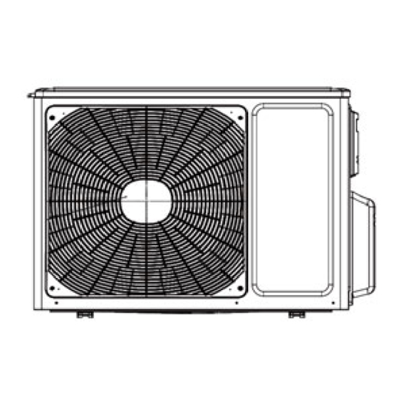
Service Manual 10. Exploded View and Parts List Model:CHML-U14NK2(CB228W06501) Installation and Maintenance... - Page 54 Service Manual Part Code Description CHML-U14NK2 Product Code CB228W06501 Front Grill 22413046 Cabinet 01433034P Chassis Sub-assy 01700000013P Gas-liquid Separator 07223048 Drainage Joint 26113009 Compressor Gasket 76710247 Compressor and fittings 00105249G Magnet Coil 4300040045 4-way Valve Assy 03015200041 Temperature Sensor 39000073...
- Page 55 Service Manual Model:CHML-U14NK2(CB228W06500) Installation and Maintenance...
- Page 56 Service Manual Part Code Description CHML-U14NK2 Product Code CB228W06500 Front Grill 22413046 Cabinet 01433034P Chassis Sub-assy 01700000013P Gas-liquid Separator 07223048 Drainage Joint 26113009 Compressor Gasket 76710247 Compressor and fittings 00105249G Magnet Coil 4300040045 4-way Valve Assy 03015200041 Temperature Sensor 39000073...
- Page 57 Service Manual Model:CHML-U18NK3(CB228W06301) Installation and Maintenance...
- Page 58 Service Manual Part Code Description CHML-U18NK3 Product Code CB228W06301 Front Grill 22413045 Front Panel 01535013P Chassis Sub-assy 0280326301P Drainage Connecter 06123401 Drainage hole Cap 06813401 Gas-liquid Separator Assy 07225017 Compressor and fittings 00105249G Magnet Coil 4300040045 4-Way Valve Assy 03073156 Right Side Plate 01303268P Valve Support Assy...
- Page 59 Service Manual Model:CHML-U18NK3(CB228W06300) Installation and Maintenance...
- Page 60 Service Manual Part Code Description CHML-U18NK3 Product Code CB228W06300 Front Grill 22413045 Front Panel 01535013P Chassis Sub-assy 02803263P Drainage Connecter 06123401 Drainage hole Cap 06813401 Gas-liquid Separator Assy 07225017 Compressor and fittings 00105249G Electrical Heater 7651300403 Magnet Coil 4300040045 4-Way Valve Assy 03073156 Right Side Plate 01303268P...
- Page 61 Service Manual Model:CHML-U21NK3(CB228W06401) Installation and Maintenance...
- Page 62 Service Manual Part Code Description CHML-U21NK3 Product Code CB228W06401 Front grill 22413045 Front Panel 01535013P Chassis Sub-assy 01700000120P Drainage Connecter 06123401 Compressor and fittings 0010524501 Compressor Gasket 76713066 Gas-liquid Separator Assy 07225017 Inhalation Tube 03500600586 Right Side Plate 01303268P Valve support assy 0713395501 Cut off Valve 07130239...
- Page 63 Service Manual Model:CHML-U21NK3(CB228W06400) Installation and Maintenance...
- Page 64 Service Manual Part Code Description CHML-U21NK3 Product Code CB228W06400 Front grill 22413045 Front Panel 01535013P Chassis Sub-assy 01700000120P Drainage Connecter 06123401 Compressor and fittings 0010524501 Compressor Gasket 76713066 Gas-liquid Separator Assy 07225017 Inhalation Tube 03500600586 Right Side Plate 01303268P Valve support assy 0713395501 Cut off Valve 07130239...
- Page 65 Service Manual Model:CHML-U24NK3(CB228W06601) Installation and Maintenance...
- Page 66 Service Manual Part Code Description CHML-U24NK3 Product Code CB228W06601 Front Grill 22413026 Cabinet 01435004P Left Handle 26235401 Front Side Plate 01305086P Drainage Connecter 06123401 Chassis Sub-assy 0280328001P Gas-liquid Separator Assy 07225017 Compressor and Fittings 0010524501 Tube Connector Sub-assy 06643008 4-Way Valve Assy 03073181 Connection Pipe 05113723...
- Page 67 Service Manual Model:CHML-U24NK3(CB228W06600) Installation and Maintenance...
- Page 68 Service Manual Part Code Description CHML-U24NK3 Product Code CB228W06600 Front Grill 22413026 Cabinet 01435004P Left Handle 26235401 Front Side Plate 01305086P Electrical Heater (Chassis) 7651000411 Drainage Connecter 06123401 Chassis Sub-assy 02803280P Gas-liquid Separator Assy 07225017 Compressor and Fittings 0010524501 Electric Heater(Compressor) 7651873215 Tube Connector Sub-assy 06643008...
- Page 69 Service Manual Model:CHML-U28NK4(CB228W06201) Installation and Maintenance...
- Page 70 Service Manual Part Code Description CHML-U28NK4 Product Code CB228W06201 Front Grill 22413048 Cabinet 01435004P Left Handle 26235401 Front Side Plate 01305086P Drainage Connecter 06123401 Chassis Sub-assy 0280328001P Gas-liquid Separator Assy 07225017 Compressor and Fittings 0010524501 Tube Connector Sub-assy 06643008 4-Way Valve Assy 03073181 Connection Pipe 05113723...
- Page 71 Service Manual Model:CHML-U28NK4(CB228W06200) Installation and Maintenance...
- Page 72 Service Manual Part Code Description CHML-U28NK4 Product Code CB228W06200 Front Grill 22413048 Cabinet 01435004P Left Handle 26235401 Front Side Plate 01305086P Electrical Heater (Chassis) 7651000411 Drainage Connecter 06123401 Chassis Sub-assy 02803280P Gas-liquid Separator Assy 07225017 Compressor and Fittings 0010524501 Electric Heater(Compressor) 7651873215 Tube Connector Sub-assy 06643008...
Need help?
Do you have a question about the CHML-U14NK2 and is the answer not in the manual?
Questions and answers