Table of Contents
Advertisement
Quick Links
Advertisement
Table of Contents

Related Manuals for Cooper & Hunter NORDIC MULTI LIGHT CHML-IC12RK


Summary of Contents for Cooper & Hunter NORDIC MULTI LIGHT CHML-IC12RK
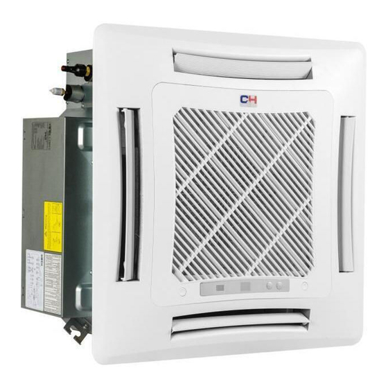
- Page 1 NORDIC MULTI LIGHT SERIES CASETTE TYPE INDOOR UNIT Service manual Air conditioners Models: CHML-IC12RK CHML-IC18RK CHML-IC24RK Thank you for choosing Cooper&Hunter air conditioner, please read this service manual carefully before operation and retain it for future reference.
-
Page 2: Table Of Contents
Service Manual Table of Contents Part Ⅰ : Technical Information ...............1 1. Summary ........................1 2. Specifications ......................2 2.1 Specification Sheet ......................2 3. Outline Dimension Diagram ................5 4. Refrigerant System Diagram ..............6 5. Electrical Part ......................7 5.1 Wiring Diagram .........................7 5.2 PCB Printed Diagram .......................9 6. - Page 3 Service Manual Appendix: ........................42 Appendix 1: Reference Sheet of Celsius and Fahrenheit ............42 Appendix 2: Configuration of Connection Pipe ..............42 Appendix 3: Pipe Expanding Method ...................43 Appendix 4: List of Resistance for Temperature Sensor ............44 Table of Contents...
-
Page 4: Part Ⅰ : Technical Information
Service Manual Part Ⅰ : Technical Information 1. Summary Indoor Unit CHML-IC12RK CHML-IC18RK CHML-IC24RK Remote Controller YT1F(MOTO) Technical Information... -
Page 5: Specifications
Service Manual 2. Specifications 2.1 Specification Sheet Parameter Unit Value Model CHML-IC12RK CHML-IC18RK Rated Voltage 220-240 220-240 Power Rated Frequency Supply Phases Cooling Capacity 3.50 4.50 Heating Capacity 4.00 Air flow volume(SH/H/M/L/SL) 650/560/520/450/- 710/670/590/450/- Dehumidifying Volume Fan Type Centrifugal Centrifugal Fan Diameter-height Φ322–148 Φ322–148... - Page 6 Service Manual Parameter Unit Value Model CHML-IC24RK Rated Voltage 220-240 Power Rated Frequency Supply Phases Cooling Capacity 7.10 Heating Capacity Air flow volume(SH/H/M/L/SL) 1280/1220/1100/880/- Dehumidifying Volume Fan Type Centrifugal Fan Diameter-height Φ450-142 Fan Motor Cooling Speed(SH/H/M/L/SL) 650/620/560/450/- Fan Motor Heating Speed(SH/H/M/L/SL) 650/620/560/460/- Fan Motor Power Output Fan motor running current...
- Page 7 Service Manual Note: Nominal capacities are based on the follow conditions. Mode Indoor Outdoor DB:27 (80.6) DB:35(95) Cooling WB:19 (66.2) WB:24(75.2) DB:20 (68) DB:7(44.6) Heating WB:--(--) WB:6 (42.8) Piping Length The air volume is measured at the relevant standard external static pressure. Noise is tested in the semianechoic room, so it should be slightly higher in the actual operation due to environmental change.
-
Page 8: Outline Dimension Diagram
Service Manual 3. Outline Dimension Diagram CHML-IC12RK CHML-IC18RK CHML-IC24RK Unit:mm Item Model CHML-IC12RK CHML-IC18RK CHML-IC24RK Technical Information... -
Page 9: Refrigerant System Diagram
Service Manual 4. Refrigerant System Diagram Technical Information... -
Page 10: Electrical Part
Service Manual 5. Electrical Part 5.1 Wiring Diagram ● Instruction Symbol Symbol Color Symbol Symbol Color Symbol Name White Green Jumper cap Yellow Brown COMP Compressor Blue Grounding wire YEGN Yellow/Green Black Violet Orange Note: Jumper cap is used to determine fan speed and the swing angle of horizontal lover for this model. ●... - Page 11 Service Manual CHML-IC24RK 600007060124 These circuit diagrams are subject to change without notice, please refer to the one supplied with the unit. Technical Information...
-
Page 12: Pcb Printed Diagram
Service Manual 5.2 PCB Printed Diagram Top view Name Interface of fan Interface of live wire Fuse Interface of netural wire Air terminal Terminal with outdoor unit communication wire Water pump control Interface of ambient temperature sensor Interface of tube temperature sensor 10 Water full detection terminal Up&down swing motor 12 Jumper cap terminal... -
Page 13: Function And Control
Service Manual 6. Function and Control 6.1 Remote Controller Introduction Buttons on remote controller ON/OFF button MODE button +/- button FAN button I FEEL button button button button CLOCK button TIMER ON/TIMER OFF button X-FAN button Note: X-FAN is the same with BLOW TEMP button TURBO button SLEEP button... - Page 14 Service Manual MODE button Press this button to select your required operation mode. AUTO COOL HEAT After selecting auto mode, air conditioner will operate automatically according to ambient temperature. Set temperature can’t be adjusted and will not be displayed as well. Press " FAN" button can adjust fan speed. Press " "...
- Page 15 Service Manual button Press this button can select up&down swing angle. Fan blow angle can be selected circularly as below: no display (horizontal louvers stops at current position) When selecting " ", air conditioner is blowing fan automatically. Horizontal louver will automatically swing up & down at maximum angle.
- Page 16 Service Manual When selecting " " with remote controller, temperature indicator on indoor unit displays outdoor ambient temperature. Note: Outdoor temperature display is not available for some models. At that time, indoor unit receives " "signal, while it displays indoor set temperature. It’s defaulted to display set temperature when turning on the unit.There is no display in the remote controller.
-
Page 17: Brief Description Of Modes And Functions
Service Manual 6.2 Brief Description of Modes and Functions 1.Basic function of system (1)Cooling mode (1) Under this mode, fan and swing operates at setting status. Temperature setting range is 16~30 (2) During malfunction of outdoor unit or the unit is stopped because of protection, indoor unit keeps original operation status. (2)Drying mode (1) Under this mode, fan operates at low speed and swing operates at setting status. - Page 18 Service Manual (8)I feel control mode After controller received I feel control signal and ambient temperature sent by remote controller, controller will work according to the ambient temperature sent by remote controller. (9)Compulsory defrosting function (1) Start up compulsory defrosting function Under ON status, set heating mode with remote controller and adjust the temperature to 16 C.
- Page 19 Service Manual (17)Instructions to the Error Indicating Lamps on the Panel of the Cassette Type Unit. Receiver "88" Dispaly" Auto" Button Power Timer "Test" Button Indicating Lamp Indicating Lamp Power and ON/OFF Indicating Lamp: It goes red when the unit is powered on while it goes white when the unit is started. Timer Indicating Lamp: Timer indicator on indoor unit will be on when timer ON is set under off status and timer OFF is set under on status.
-
Page 20: Part Ⅱ : Installation And Maintenance
Service Manual Part Ⅱ : Installation and Maintenance 7. Notes for Installation and Maintenance Safety Precautions: 10. If the power cord or connection wire is not long enough, please get the specialized power cord or connection wire Important! from the manufacture or distributor. Prohibit prolong the wire by yourself. - Page 21 Service Manual Safety Precautions for Installing and Relocating the Unit: To ensure safety, please be mindful of the following precautions. Warnings 1. When installing or relocating the unit, be sure to keep the refrigerant circuit free from air or substances other than the specified refrigerant.
- Page 22 Service Manual Main Tools for Installation and Maintenance 1. Level meter, measuring tape 2. Screw driver 3. Impact drill, drill head, electric drill 4. Electroprobe 5. Universal meter 6. Torque wrench, open-end wrench, inner hexagon spanner 7. Electronic leakage detector 8.
-
Page 23: Installation
Service Manual 8. Installation 8.1 Installation Dimension Diagram Indoor Installation and Maintenance... -
Page 24: Installation Of Cassette Type
Service Manual 8 8 8 . . . 2 2 2 I I I n n n s s s t t t a a a l l l l l l a a a t t t i i i o o o n n n o o o f f f C C C a a a s s s s s s e e e t t t t t t e e e T T T y y y p p p e e e 8.2.1. - Page 25 Service Manual 8.2.3. Installing the Suspension Bolts (2) Place the panel at the unit, and latch the hooks beside and opposite the swing flap motor. (1) Using the installation template, drill holes for bolts (four (3) Latch other two hooks. holes).
-
Page 26: Maintenance
Service Manual 9. Maintenance 9.1 Error Code List If cut-off of water level switch is detected for 8s successively once Full water Water level energized, the system will enter protection switch full water protection. In this case, switch off the unit and then switch it on to eliminate this malfunction. -
Page 27: Troubleshooting For Main Malfunction
Service Manual 9.2 Troubleshooting for Main Malfunction ●Indoor unit: 1. Malfunction of Temperature Sensor F1, F2 Main detection points: ● Is the wiring terminal between the temperature sensor and the controller loosened or poorly contacted? ● Is there short circuit due to trip-over of the parts? ●... - Page 28 Service Manual 2. Malfunction of Blocked Protection of IDU Fan Motor H6 Start Turn the fan blades by hand under power-off condition Adjust the motor and blade Whether the fan blades assembly so that rotor can run can run smoothly? smoothly.
- Page 29 Service Manual 3. Malfunction of Protection of Jumper Cap C5 Main detection points: ● Is there jumper cap on the mainboard? ● Is the jumper cap inserted correctly and tightly? ● The jumper is broken? ● The motor is broken? ●...
- Page 30 Service Manual 4. Communication malfunction E6 Start Cut off power supply. Check if connection line of IDU and ODU and the wire inside electric box are correctly connected. Connect the line Correct connection? according to Malfunction eliminated? wiring diagram. Main board matches Match correctly with display board? Main board of Malfunction eliminated?
- Page 31 Service Manual Troubleshooting for F0 malfunction Heat exchangers are Clean the heat exchangers and remove Malfunction is too dirty or the air inlet/outlet eliminated. blockage of air inlet/outlet. is blocked. Compressor doesn't work Malfunction is Make compressor run normally. normally. Strange noise or leakage occurs. eliminated.
- Page 32 Service Manual 6. Full Water Protection E9 Installation and Maintenance...
-
Page 33: Maintenance Method For Normal Malfunction
Service Manual 9.3 Maintenance Method for Normal Malfunction 1. Air Conditioner Can't be Started Up Possible Causes Discriminating Method (Air conditioner Status) Troubleshooting Confirm whether it's due to power failure. If yes, No power supply, or poor After energization, operation indicator isn’t bright wait for power recovery. - Page 34 Service Manual 4. ODU Fan Motor Can't Operate Possible causes Discriminating method (air conditioner status) Troubleshooting Connect wires according to wiring diagram to Wrong wire connection, or poor Check the wiring status according to circuit make sure all wiring terminals are connected connection diagram firmly...
-
Page 35: Exploded View And Parts List
Service Manual 10. Exploded View and Parts List CHML-IC12RK The component picture is only for reference; please refer to the actual product. Installation and Maintenance... - Page 36 Service Manual Part Code Description CHML-IC12RK Rear Grill 26909400007 Brushless DC Motor 15709400004 Water Tray Assy 01289400004 Water Pump 4313800005801 Supporter 01809400007 Water Level Switch 450102013 Pump Drainpipe 26909400069 Water Pump Assy 70148003 Right Side Plate Sub-Assy 01319400013 Bottom Foam Assy 12509400004 Base Plate Assy 02229400007...
- Page 37 Service Manual CHML-IC18RK The component picture is only for reference; please refer to the actual product. Installation and Maintenance...
- Page 38 Service Manual Part Code Description CHML-IC18RK Rear Grill 26909400007 Brushless DC Motor 15709400004 Water Tray Assy 01289400004 Water Pump 4313800005801 Supporter 01809400007 Water Level Switch 450102013 Pump Drainpipe 26909400069 Water Pump Assy 70148003 Right Side Plate Sub-Assy 01319400013 Bottom Foam Assy 12509400004 Base Plate Assy 02229400007...
- Page 39 Service Manual CHML-IC24RK The component picture is only for reference; please refer to the actual product. Installation and Maintenance...
- Page 40 Service Manual Part Code Description CHML-IC24RK Electric Box Assy 100002060082 Terminal Board 420001000002 Electric Base Plate 01412721 Water Tray Assy 000069000104 Fan Fixer 10312701 Centrifugal Fan 10312705 Evaporator Assy 01029400045 Left Side Plate Assy 01302715 Front Side Plate assy 01302718 Base Plate Assy 01222701 Connected Board Assy of Evaporator...
-
Page 41: Removal Procedure
Service Manual 11. Removal Procedure Warning: Be sure to wait for a minimum of 20 minutes after turning off all power supplies and discharge the refrigerant completely before removal. 1. Loosen the screws fixing the water tray Use screwdriver to loosen the screws fixing the water tray 2. - Page 42 Service Manual 4. Remove the fan Remove the fan 5. Loosen the screws fixing the motor Use screwdriver to loosen the screws fixing the motor 6. Remove the motor and replace it Remove the motor and replace it 7. Tighten the screws fixing the motor Use screwdriver to tighten the screws fixing the motor.
- Page 43 Service Manual 8. Mount the fan and tighten the fixing bolts Mount the fan and use spanner to tighten the bolts fixing the fan. 9. Mount the water tray and tighten the screws Use screwdriver to loosen the screws fixing the water tray 10.Removal and Installation of Drainage Pump Loosen the screws...
- Page 44 Service Manual Take out the pump and replace it Connect the drainage pipe and use screwdriver to tighten the screws fixing the water pump. Mount the water tray and tighten the screws Use screwdriver to loosen the screws fixing the water tray Installation and Maintenance...
-
Page 45: Appendix
Service Manual Appendix: Appendix 1: Reference Sheet of Celsius and Fahrenheit Conversion formula for Fahrenheit degree and Celsius degree: Tf=Tcx1.8+32 Set temperature Fahrenheit Fahrenheit Fahrenheit display Fahrenheit display Fahrenheit display Fahrenheit Celsius( Celsius( Celsius( temperature temperature temperature 60.8 69/70 69.8 78/79 78.8 62/63... -
Page 46: Appendix 3: Pipe Expanding Method
Service Manual Appendix 3: Pipe Expanding Method Pipe Note: Pipe cutter Improper pipe expanding is the main cause of refrigerant leakage.Please expand the pipe according to the following steps: Leaning Uneven Burr A:Cut the pip ● Confirm the pipe length according to the distance of indoor unit and outdoor unit. ●... -
Page 47: Appendix 4: List Of Resistance For Temperature Sensor
Appendix 4: List of Resistance for Temperature Sensor Resistance Table of Ambient Temperature Sensor for Indoor and Outdoor (15K) Temp( C) Resistance(kΩ) Temp( C) Resistance(kΩ) Temp( Resistance(kΩ) Temp( Resistance(kΩ) 138.1 18.75 3.848 1.071 128.6 17.93 3.711 1.039 121.6 17.14 3.579 1.009 16.39 3.454... - Page 48 Resistance Table of Tube Temperature Sensors for Outdoor and Indoor (20K) Temp( C) Resistance(kΩ) Temp( C) Resistance(kΩ) Temp( Resistance(kΩ) Temp( Resistance(kΩ) 181.4 25.01 5.13 1.427 171.4 23.9 4.948 1.386 162.1 22.85 4.773 1.346 153.3 21.85 4.605 1.307 20.9 4.443 1.269 137.2 4.289 1.233...
- Page 49 Resistance Table of Discharge Temperature Sensor for Outdoor (50K) Temp( C) Resistance(kΩ) Temp( Resistance(kΩ) Temp( C) Resistance(kΩ) Temp( Resistance(kΩ) 853.5 18.34 4.75 799.8 93.42 17.65 4.61 89.07 16.99 4.47 703.8 84.95 16.36 4.33 660.8 81.05 15.75 4.20 620.8 77.35 15.17 4.08 580.6 73.83...
- Page 50 Cooper&Hunter International Corporation www.cooperandhunter.com...
Need help?
Do you have a question about the NORDIC MULTI LIGHT CHML-IC12RK and is the answer not in the manual?
Questions and answers