
Subscribe to Our Youtube Channel
Related Manuals for Cooper & Hunter CH-M12K6B


Summary of Contents for Cooper & Hunter CH-M12K6B
- Page 1 INSTALLATION MANUAL PORTABLE AIR CONDITIONER Model: CH-M12K6B F or proper operation, please read and keep this manual carefully. Designed by Cooper&Hunter International Corporation, Oregon, USA www.cooperandhunter.com...
-
Page 2: Table Of Contents
Content Operation Notices Operation Environment ....................1 Safety Warning ......................2 Part's Name ......................3 Installation Notice Installation Precaution .....................4 Preparation before Installation ................5 Installation Install Wire Hook .....................6 Removing Collected Water ..................7 Installation in a double-hung sash window(Optional)..........10 Installation in a sliding sash window(Optional)............13 Installation and Disassembly of Heat Discharge Pipe ...........16 Attached Sheet Operation Test .......................19... - Page 3 Explanation of Symbols Indicates a hazardous situation that, if not avoided, will DANGER result in death or serious injury. Indicates a hazardous situation that, if not avoided, could WARNING result in death or serious injury. Indicates a hazardous situation that, if not avoided, may CAUTION result in minor or moderate injury.
-
Page 4: Operation Environment
Operation Environment ● The air conditioner must be operated within the temperature range: 16°C ~ 35°C. ● The appliance is for indoor use only. ● The appliance must be positioned so that the plug is accessible. ● This air conditioner can only be used for family, not for commercial industry. -
Page 5: Safety Warning
Safety Warning ● This appliance can be used by children aged from 8 years and above and persons with reduced physical,sensory or mental capabilities or lack of experience and knowledge if they have been given supervision or instruction concerning use of the appliance in a safe way and understand the hazards involved. -
Page 6: Part's Name
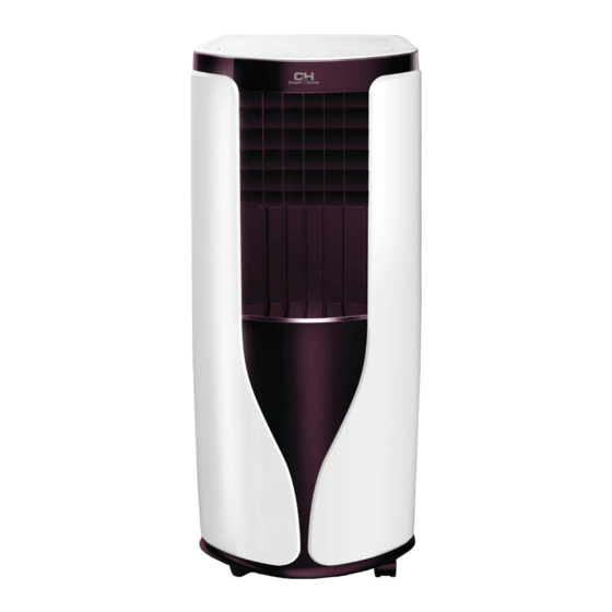
Part's Name Controller panel Guide louver Swing louver Castor Wire-fixing hook Plug of power cord Gastor Air inlet Joint A Heat discharge pipe Joint B+C Remote controller hook 11 10 AUTO HEALTH X-FAN HUMIDITY FILTER TURBO HOUR ON/OFF ON/OFF MODE X-FAN TEMP TIMER... -
Page 7: Installation Precaution
Installation Precaution WARNING: ● Observe all governing codes and ordinances. ● Do not use damaged or non-standard power cord. ● Be caution during installation and maintenance. Prohibit incorrect operation to prevent electric shock, casualty and other accidents. Selection of installation location Basic requirement Installing the unit in the following places may cause malfunction. -
Page 8: Preparation Before Installation
Preparation before Installation NOTICE: Check if the accessories are available before installation. Accessory list joint A joint B joint C heat discharge pipe screw(3) pipe clip rubber plug pipe hoop (2) wire hook (2) AUTO HEALTH X-FAN HUMIDITY FILTER TURBO HOUR ON/OFF ON/OFF... -
Page 9: Install Wire Hook
Install Wire Hook ● Assemble the wire hook at the back of the unit with screws (the direction of wire direction of wire hook is upward wire hook screw direction of wire hook is downward ● Wind the power cord around the wire hook. -
Page 10: Removing Collected Water
Removing Collected Water There are 2 ways to remove collected water: Use the continuous drainage option from the lower hole. NOTICE: When using the continuous drainage option from the bottom hole, install drainage pipe as follow before using, otherwise poor drainage will affect normal operation of the unit. - Page 11 Removing Collected Water ■ Drainage way as follows. 1. In Cool, Dry or Heat mode operating, the condensation water will be drained to the chassis. 2. When the chassis is full with water, the buzzer will give out 8 sounds and "H8" is displayed to remind user to discharge water: ●...
- Page 12 Removing Collected Water Use the continuous drainage option from the middle hole NOTICE: Water can be automatically emptied into a floor drain by attaching 14mm inner diameter hose (not included). 1. Remove the continuous drain cap 1 by turning it counter clockwise then remove the rubber stopper 2 from the spout.
-
Page 13: Installation In A Double-Hung Sash Window(Optional)
Installation in a double-hung sash window(Optional) 1. Connect the rain guards to the insect guard net. Insert all three projections on each rain guard into the holes in the insect guard net. Side “A” will now be at the top, as indicated in the diagram. Hole Insect guard net Rain guard... - Page 14 Installation in a double-hung sash window(Optional) The window panel cannot be installed in windows less than 520mm (20.5") wide, as you will be unable to shut the exhaust cover. (1) Open the window sash and place the window panel on the window sill. (2) Secure the window panel to the window stool with 2 screws.
- Page 15 Installation in a double-hung sash window(Optional) 5. Close the window sash securely against the Window panel. 6. Stuff the foam seal B between the glass and the window to prevent air and insects from getting into the room. 7. Attach the bracket with a screw.(Recommended) Bracket Please lay a tabular material underneath the window panel in case you could not attach the rain guard or the window adapter properly due to the deep...
-
Page 16: Installation In A Sliding Sash Window(Optional)
Installation in a sliding sash window(Optional) 1. Connect the rain guards to the insect guard net. Insert all three projections on each rain guard into the holes in the insect guard net. Side “A” will now be at the top, as indicated in the diagram. "A"... - Page 17 Installation in a sliding sash window(Optional) The window panel cannot be installed in windows less than 520mm (20.5") high, as you will be unable to shut the exhaust cover. (1) Open the window sash and place the window panel on the window frame. (2) Secure the window panel to the window frame with 2 screws.
- Page 18 Installation in a sliding sash window(Optional) 5. Close the window sash securely against the Window panel. 6. Stuff the foam seal B between the glass and the window to prevent air and insects from getting into the room. 7. Attach the bracket with a screw.(Recommended) Bracket Please lay a tabular material underneath the window panel in case you could not attach the rain guard or the window adapter properly due to the deep...
-
Page 19: Installation And Disassembly Of Heat Discharge Pipe
Installation and Disassembly of Heat Discharge Pipe Install heat discharge pipe 1. Rotate joint A and joint B clockwise into the two ends of heat discharge pipe. clockwise clockwise joint A heat discharge pipe joint B+C 2. Insert joint A of heat clasp the side with "TOP"... - Page 20 Installation and Disassembly of Heat Discharge Pipe Note of Installingheat discharge pipe correct correct correct wrong ● The length of the heat discharge pipe is less than 1m. It is recommended to use it with shortest length. When installing,heat discharge pipe should be as flat as possible. Don’t prolong the pipe or connect it with other heat discharge pipe.
- Page 21 Installation and Disassembly of Heat Discharge Pipe would easily cause malfunction.) Disassemble heat discharge pipe 1. Remove joint A: 2. Remove joint B+C from Press the clasp and lift joint A upwards to outdoors. remove it. clasp upwards disassemble joint A joint B+C...
-
Page 22: Operation Test
Installation and Disassembly of Heat Discharge Pipe 3. Remove the window adapter. Pull out and remove the window adapter by pushing down two “PUSH” markings, and slide and close the exhaust cover in the window panel. (Optional) "PUSH" "PUSH" Operation Test ●... -
Page 23: Electric Schematic Diagram
Electric Schematic Diagram C H- M12K6B TUBE TEMP. OUTTUBE TEMP. ROOM TEMP. WATER MOTOR SENSOR SENSOR COLD PLASMA SENSOR RECEIVER POWER GENERATOR BN(BK) BOARD YEGN BU(WH) YEGN(GN) HEALTH-N HEALTH-L ROOM TUBE OUTTUBE WATER DISP2 AC-L DISP2 MAIN BOARD K201 COMP. YEGN DISP1 COMP... - Page 24 www.cooperandhunter.com MANUFACTURER: GREE ELECTRIC APPLIANCES, INC. OF ZHUHAI 66160000460 Add: West Jinji Rd, Qianshan, Zhuhai, Guangdong, China, 519070...
Need help?
Do you have a question about the CH-M12K6B and is the answer not in the manual?
Questions and answers