Table of Contents
Advertisement
Quick Links
Advertisement
Table of Contents

Related Manuals for Parrot Uncle BBCF860


Summary of Contents for Parrot Uncle BBCF860
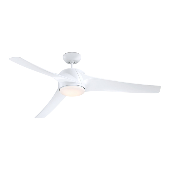
- Page 1 CEILING FAN 60” Ceiling Fan Owner’s Manual BBCF860...
-
Page 2: Table Of Contents
Table of Contents Section Page Section Page Safety Instructions ......... 2 12. -
Page 3: Unpacking Instructions
This product is designed to use only those parts Fan Blades supplied with this product and/or any accessories designated specifically for use with this product Light Kit Assembly by Parrot Uncle. Shade No-Light Plate Wall Control Open carton containing fan. Remove top half of styrofoam unit. -
Page 4: Electrical Requirements
1. Unpacking Instructions (Continued) This Manual Is Designed to Make it as Easy as Possible for You to Assemble, Install, Operate and Maintain Your Ceiling Fan THIS FAN IS SUITABLE FOR DAMP LOCATIONS SUCH AS COVERED PORCHES, COVERED PATIOS, AND COVERED DECKS. ANYWHERE THERE IS A ROOF OVERHEAD. -
Page 5: Ceiling Fan Assembly
3. Ceiling Fan Assembly FAN MOTOR Flip the upper foam pad over and place on a stable ASSEMBLY working surface. Remove the Fan Motor Assembly from the protective plastic bag. Place Fan Motor Assembly on top of the foam pad with the Upper Motor Cover supporting the weight of the Motor (Figure 1). - Page 6 3. Ceiling Fan Assembly (Continued) ROTATE CLOCKWISE LIGHT KIT ADAPTER Remove One of the Three Pan Head Screws from the Motor Assembly Hub, retain the Screw for future use. PAN HEAD SCREW Loosen the remaining Two Screws (Figure 3). Place the 2-pin Motor Assembly connector through the large Center Hole of the Light Kit Adapter (Figure 3).
- Page 7 3. Ceiling Fan Assembly (Continued) BLADE SCREWS NOTE: Installation of the Blade will be complete (2 per blade assembly) after this step: Align the Two Blade Tab Holes of One Blade with the BLADE threaded Holes of the Motor and install a Washer Head ASSEMBLY (3) Screw into each Hole (Figure 5).
- Page 8 3. Ceiling Fan Assembly (Continued) TWO 80” MOTOR WIRES (UNTWISTED) TWO 80" MOTOR LEADS (UNTWISTED) Separate, untwist and unkink the Two 80” Motor Wires. Route the Two Motor Wires through the 4.5” Downrod (Figure 7). 4.5" DOWNROD Figure 7 Loosen the Two Phillips Head Set Screws in the Motor Coupler for installation of the Downrod (Figure 8).
- Page 9 3. Ceiling Fan Assembly (Continued) 3.10 4.5" DOWNROD Make sure the Grommet is properly installed in the Motor Coupler Cover, then slide the Motor Coupler Cover on the COUPLER COUPLER COVER Downrod until it rests on the Motor Housing (Figure 10). COVER GROMMET Figure 10...
-
Page 10: How To Hang Your Ceiling Fan
3. Ceiling Fan Assembly (Continued) 3.13 1/2-INCH The Fan comes with Black and White Wires that are BLACK WIRE 80-inches long. Measure up approximately 6 to 9-inches above top of WHITE WIRE 6 TO 9 Hanger Ball/4.5” Downrod Assembly (Figure 13). INCHES Cut off excess Wires and strip back insulation 1/2-inch HANGER BALL... - Page 11 Securely attach the Hanger Bracket to the Outlet Box using the Two Screws supplied with the Outlet Box (Figure 15). OUTLET HANGER TWO SCREWS BRACKET SUPPLIED WITH OUTLET BOX ANTI-ROTATION Figure 15 Carefully lift the Fan and seat the Hanger Ball/ Downrod Assembly on the Hanger Bracket that was just attached to the Outlet Box (Figure 16).
-
Page 12: Light Kit Assembly
5. Light Kit Assembly Skip to Section 6.0 if not installing the supplied light kit. Remove one of the Three Screws in the Light REMOVE LIGHT Kit Adapter and loosen the remaining Two Screws KIT ADAPTER PAN (Figure 17). HEAD SCREW Retain the Screw for future use. -
Page 13: Optional Installation Of No-Light Plate Assembly
5. Light Kit Assembly (Continued) Place the Shade into the opening of the Light Kit Adapter, aligning the Three Flat Areas on the Top Edge of the Shade with the Three Raised Dimples on the Light Kit Adapter and turn the Shade clockwise until it stops (Figure 20). - Page 14 6. Optional Installation No-Light Plate Assembly (Continued) Disengage the Fan Motor Assembly 2-Pin Wire Connector from the 2-Pin Wire Connector of the Light Kit Assembly (Figure 23). Store Light Kit Assembly in a safe location for future REINSTALL LIGHT KIT ADAPTER PAN installation.
-
Page 15: How To Wire Your Ceiling Fan
7. How to Wire Your Ceiling Fan If you feel that you do not have enough electrical wiring knowledge or experience, have your fan installed by a licensed electrician. GROUND CONDUCTOR SUPPLY WARNING To avoid possible electrical shock, be sure electricity is turned off at the main fuse box or circuit breaker LISTED WIRE panel before wiring. - Page 16 7. How to Wire Your Ceiling Fan (Continued) Securely connect the Fan Motor White Wire to the Supply White (neutral) Wire using Wire Connector SUPPLY WHITE (supplied) Figure 26). (NEUTRAL) LISTED WIRE CONNECTOR FAN MOTOR WHITE WIRE Figure 26 Securely connect the Fan Motor Black Wire to the Supply Black (hot) Wire using Wire Connector (supplied) (Figure 27).
-
Page 17: Final Assembly
8. Final Assembly Screw the Two Threaded Studs (supplied) into the Tapped Holes in the Hanger Bracket (Figure 29). THREADED STUDS (2) Figure 29 Lift the Ceiling Cover up to the Threaded Studs and turn until Studs protrude through the Holes in the Ceiling Cover (Figure 30). -
Page 18: Wall Control Procedures
9. Wall Control Procedures Code Switches in the Transmitter may be set in 32 different positions. If your Fan and Light turn ON and Your Ceiling Fan/Light Control consists of Wall OFF without using your Control, you may be getting Mounted Transmitter and a Receiver located inside interference from other remote units such as garage the Ceiling Cover. -
Page 19: Wall Control Installation
10. Wall Control Installation NOTE: Make all wiring connections using WARNING Wire Connectors (supplied). Make sure that all connections are tight, including ground, and that no Turning off wall switch is not sufficient. To avoid bare wire is visible at the wire connectors, except possible electrical shock, be sure electricity is turned for the ground wire. - Page 20 10. Wall Control Installation (Continued) Skip to Section 10.4 if Using a 3-way Switch Installation. SCREWS (2) SCREWS (2) FAN/LIGHT WALL CONTROL SINGLE-POLE INSTALLATION (One Fan Controlled by One Wall Control) (See Figure 33)..WARNING Turning off wall switch is not sufficient. To avoid possible electrical shock, be sure electricity is turned NEUTRAL SWITCH COVER...
- Page 21 10. Wall Control Installation (Continued) 3-WAY INSTALLATION FAN/LIGHT SECOND FAN/LIGHT (One Fan Controlled by Two Different Wall Controls) WALL WALL CONTROL CONTROL (Purchased Separately) (See Figures 34 and 35). WARNING GROUND GROUND Turning off wall switch is not sufficient. To avoid possible electrical shock, be sure electricity is turned off at the main fuse box or circuit breaker panel before TRAVELER...
- Page 22 10. Wall Control Installation (Continued) 10.5 STANDARD WIRING FOR EXISTING Disconnect Electrical Power to the Branch Circuit at 3-WAY SWITCHES the Circuit Breaker Panel or Main Fuse Box before EXISTING EXISTING attempting to install the Ceiling Fan Wall Control into WALL CONTROL WALL SWITCH the Wall Box.
-
Page 23: Programming The Receiver Operating Frequency & High Speed Conditioning Of Fan Control
11. Programming the Receiver Operating Frequency & High Speed Conditioning of Fan Control -- Important - Read This Section Carefully and Follow the High Speed Conditioning Instructions Closely -- IMPORTANT: Ceiling fan blades MUST be installed the electronic motor control software is calculating before high speed conditioning can begin. -
Page 24: Using Your Ceiling Fan
12. Using Your Ceiling Fan WARNING Fan installation must be completed, including the installation of the fan blades, before testing the fan control. POWER Your Wall Control has full control of your Fan and Light INDICATOR (Figure 36). LIGHT LIGHT AIRFLOW INTENSITY 12.1... -
Page 25: Maintenance
13. Maintenance IMPORTANT CARE INSTRUCTIONS WARNING for your Ceiling Fan Do not use water when cleaning your ceiling fan. Periodic cleaning of your new ceiling fan is the only It could damage the motor or the blades and create the maintenance that is needed. -
Page 26: Light Kit Led Array Assembly Replacement
15. Light Kit LED Array Assembly Replacement 15.1 WARNING Disconnect Electrical Power to the Branch Circuit at To avoid possible electrical shock, be sure electricity the Circuit Breaker Panel or Main Fuse Box before is turned off at the main fuse box or circuit breaker attempting to install the Ceiling Fan to the Outlet Box. -
Page 27: Light Kit Led Driver Replacement
15. Light Kit LED Array Assembly Replacement (Continued) 15.4 Disengage the Fan Motor Assembly 2-Pin Wire Connector from the 2-Pin Wire Connector of the Light Kit Assembly (Figure 39). 15.5 Install new Light Kit Assembly by following the Section 5, Steps 5.2 through 5.4. Restore electricity and verify function of the Light Kit. - Page 28 16. Light Kit LED Driver Replacement (Continued) 16.2 Remove the Two Knurled Knobs and Lockwashers from the Threaded Studs. Retain the Hardware for future reinstallation (Figure 40). CEILING COVER Slide the Ceiling Cover downward to rest on top the Motor Housing. THREADED STUDS (2) LOCKWASHERS (2)
- Page 29 16. Light Kit LED Driver Replacement (Continued) 16.5 COUPLER NOTE: You may need help of an assistant to hold COVER the ceiling cover, coupler cover and upper motor cover up and away from the motor housing, while performing the following steps. Slide the Motor Coupler Cover up the Downrod to access the top of the Motor Housing (Figure 43).
- Page 30 16. Light Kit LED Driver Replacement (Continued) 16.8 LIGHT KIT LED DRIVER MOTOR DC POWER Squeeze and unclip the Motor AC Power Connector DC POWER CONNECTOR CONNECTOR from the Light Kit LED Driver Connector (Figure 46). LIGHT KIT LED DRIVER Squeeze and unclip the Motor DC Power Connector from the Light Kit LED Driver Connector (Figure 46).
- Page 31 16. Light Kit LED Driver Replacement (Continued) 16.11 LIGHT KIT LED DRIVER MOTOR DC POWER DC POWER CONNECTOR Reconnect the Motor AC Power Connector to the Light CONNECTOR NEW LIGHT Kit LED Driver Connector (Figure 49). KIT LED DRIVER Reconnect the Motor DC Power Connector to the Light Kit LED Driver Connector (Figure 49).
-
Page 32: Troubleshooting
WARNING Make sure main power is turned OFF. WARNING Make sure main power is turned OFF.
Need help?
Do you have a question about the BBCF860 and is the answer not in the manual?
Questions and answers